Advances in Haptics Part 14 ppt
Bạn đang xem bản rút gọn của tài liệu. Xem và tải ngay bản đầy đủ của tài liệu tại đây (7.41 MB, 45 trang )
SensoryPropertiesinFusionofVisual/HapticStimuliUsingMixedReality 577
Results
The estimated haptic and visual discrimination thresholds are shown in Tables 1 and 2.
Visual discrimination thresholds are defined at 0.4-mm interval, but haptic discrimination
thresholds are not. In order to investigate how visual/haptic stimuli interact with each
other, common criteria are necessary. We define the common criteria as the minimum per-
ceivable seven steps for both of visual/haptic discrimination thresholds, 0.2, 0.6, 1.0, 1.4, 1.8,
2.2, and 2.6 mm. Although, humans can discriminate differences less than 0.1 mm, due to
the limitations of the accuracy processing machinery, it is not possible to estimate haptic
discrimination thresholds less than 0.1 mm.
By considering different thresholds of visual and haptic information, we quantize the scale
of the curvature radii into seven identical parts: 0.2, 0.6, 1.0, 1.4, 1.8, 2.2, and 2.6 mm.
Standard Stimulus
(mm)
Discrimination
Threshold (mm)
Standard
Deviation
0.2 0.332 0.057
0.6 0.382 0.078
1.0 0.395 0.062
1.4 0.322 0.052
1.8 0.338 0.045
Table 1. Visual Discrimination Threshold
Table 2. Haptic Discrimination Threshold
4.3 Procedure of Subjective Evaluation
First, as a reference of the matching process, subjects were presented a standard stimulus in
three ways: only haptic, only visual, and both. When subjects are indicated to observe the
object by using only haptic, subjects close the eyes, and then the experimenter leads their
hand onto the object. When subjects are indicated to observe the object by only vision, sub-
jects watch the object with putting their hands on the experimental table. When subjects are
indicated to observe the object by using haptic and vision, subjects can watch and touch the
object without any physical constraints.
After observing a standard stimulus, subjects are required to determine a corresponding
stimulus by using only haptic, only vision, and both haptic and vision together. In all trials,
subjects are permitted to take as much time as needed. The displayed stimuli for match-up
are randomly chosen to control for order effects. When subjects require observing the next
stimulus for match-up, the stimulus will be displayed after 15 seconds interval.
Standard Stimulus
(mm)
Discrimination
Threshold (mm)
Standard
Deviation
0.0 0.000 0.000
0.1 0.000 0.000
0.2 0.130 0.053
0.4 0.270 0.078
0.7 0.238 0.049
1.0 0.237 0.069
1.3 0.300 0.063
1.6 0.418 0.095
There are nine combinations of three displaying ways for standard stimulus and three dis-
playing ways for mach-up stimuli. By executing multiple classification analysis to the result
derived by the all combinations, we investigate whether human perception is affected by
fusing visual and haptic cues.
If we conduct the experiment by using all perceivable seven steps for both of visual/haptic
discrimination thresholds, huge amount of time and labor is needed. On the other hand, it is
difficult to extract significant evidence to show that human perception is affected by fusing
visual and haptic cues in the most of the trials, when the one stimulus is too week to affect
the other stimulus. Thus, we conduct a preliminary experiment to choose combinations of
visual and haptic stimuli that can easily introduce the influence caused by the fusion. As the
result, a combination {visual: 2.2 mm / haptic 1.4 mm} is selected.
4.4 Result and Discussion
Results are illustrated in Figure 16 and Figure 17. The horizontal axis represents the types of
matching procedures, and the vertical axis represents the mean evaluating value of the radii
of edges. The line with rhombus nodes is the mean matching response when standard stim-
uli are presented only by haptic, the line with triangle nodes is only using vision, and the
line with box nodes is using haptic and vision together.
In the first evaluation, subjects were given a 1.4 mm haptic curvature radius as a haptic
stimulus and a 2.2 mm vision curvature radius as a visual stimulus. The result is shown in
Figure 16.
When subjects received a standard stimulus as a 1.4 mm haptic curvature radius and deter-
mined a corresponding stimulus by only using haptic (the left rhombus node), they sensed it
as 1.40±0.0 mm. On the other hand, when subjects received a standard stimulus as a 1.4 mm
haptic curvature radius and a 2.2 mm vision one and determined a corresponding stimulus
by only using haptic (the left box node), they sensed it as 1.64±0.2 mm by perceiving that the
edge was blunter than the previous result. This result was derived by presenting a 2.2 mm
vision stimulus as the standard stimulus.
When subjects received a standard stimulus as a 2.2 mm vision curvature radius and deter-
mined a corresponding stimulus by only using vision (the right triangle node), they sensed
it as 2.20±0.0 mm. On the other hand, when subjects received a standard stimulus as a 1.4
mm haptic curvature radius and a 2.2 mm vision one and determined a corresponding
stimulus by only using vision (the right box node), they sensed it as 2.12±0.4 mm by perceiv-
ing that the edge was sharper than the previous result. This result was derived by present-
ing a 1.4 mm haptic stimulus as the standard stimulus.
When subjects received a standard stimulus as a 1.4 mm haptic curvature radius and a 2.2
mm vision one and determined a corresponding stimulus by using both haptic and vision
(the middle box node), they sensed it as 1.84±0.1 mm. This experiment shows that the haptic
stimulus seems to be affected by visual stimulus when discrepancy exists between vision
and haptic stimuli.
By applying the Student's t-test to our evaluation data, significance differences were found
in effectiveness, caused by presenting a standard stimulus in three ways (F(2.18) = 26.694,
p<0.05).
AdvancesinHaptics578
Fig. 16. Mean grit sizes selected as matches for visual/haptic, and visual/haptic standards;
subjects touched an object with a 1.4 mm haptic curvature radius and a 2.2 mm vision one.
In the second evaluation, we switch the value of visual/haptic stimuli to control the order
effect. Thus, a subject is given a 2.2 mm haptic curvature radius as a haptic stimulus and a
1.4 mm vision curvature radius as a visual stimulus. The result is shown in Figure 17.
When subjects received a standard stimulus as a 2.2 mm haptic curvature radius and deter-
mined a corresponding stimulus by only using haptic (the left rhombus node), they sensed it
as 2.20±0.0 mm. On the other hand, when subjects received a standard stimulus as a 2.2 mm
haptic curvature radius and a 1.4 mm vision one and determined a corresponding stimulus
by only using haptic (the left box node), they sensed it as 2.16±0.2 mm by perceiving that the
edge was sharper than the previous result. This result is derived by presenting a 1.4 mm
vision stimulus as the standard stimulus.
When subjects received a standard stimulus as a 2.2 mm haptic curvature radius and a 1.4
mm vision one and determined a corresponding stimulus by using both haptic and vision
(the middle box node), they sensed it as 2.04±0.2 mm. This experiment shows that the haptic
stimulus seems to be affected by visual stimulus when discrepancy exists between vision
and haptic stimuli.
By applying the Student's t-test to our evaluation data, significance differences were found
in effectiveness, caused by presenting a standard stimulus in three ways, (F(2.18)=36.394,
p<0.05).
Fig. 17. Mean grit sizes selected as matches for visual/haptic, and visual/haptic standards;
subjects touched an object with a 2.2 mm haptic curvature radius and a 1.4 mm vision one
These results of subjective evaluations for the sharpness of a cube’s edge show that users
perceive an edge to be controllable by presenting a duller or sharper CG edge.
We calculated the occupancy rate of haptic and vision stimuli for the evaluations by using
the method introduced in Lederman’s paper (Lederman & Abbott, 1981). Haptic and visual
influences are calculated by the following equations:
standard) Mean(Touch-standard)Vision Mean(
standard)n Mean(Visio-standard)Vision Vision Mean(
influence Haptic
(1)
standard) Mean(Touch-standard)Vision Mean(
standard) Mean(Touch-standard)Vision Mean(Touch
influence Visual
(2)
In these equations, Mean (Touch+Vision standard) is the mean evaluating value of the ra-
dius of an edge calculated from all subject evaluations that were presented standard haptic
and vision stimuli. Mean (Vision standard) is the mean evaluating value of the radius of an
edge calculated from all subject evaluations that were presented a standard vision stimulus.
Mean (Touch standard) is the mean evaluating value of the radius of an edge calculated
from all evaluations that were presented a standard haptic stimulus.
In the first evaluation, the occupancy rate of the vision stimulus is 57.1% and the haptic
stimulus is 42.9%. In the second evaluation, the occupancy rate of the vision stimulus is
77.8% and the haptic stimulus is 22.2%. These results show that when a curvature radius
becomes larger, the haptic sensation becomes duller. As a result, the occupancy rate of the
vision stimulus increases.
SensoryPropertiesinFusionofVisual/HapticStimuliUsingMixedReality 579
Fig. 16. Mean grit sizes selected as matches for visual/haptic, and visual/haptic standards;
subjects touched an object with a 1.4 mm haptic curvature radius and a 2.2 mm vision one.
In the second evaluation, we switch the value of visual/haptic stimuli to control the order
effect. Thus, a subject is given a 2.2 mm haptic curvature radius as a haptic stimulus and a
1.4 mm vision curvature radius as a visual stimulus. The result is shown in Figure 17.
When subjects received a standard stimulus as a 2.2 mm haptic curvature radius and deter-
mined a corresponding stimulus by only using haptic (the left rhombus node), they sensed it
as 2.20±0.0 mm. On the other hand, when subjects received a standard stimulus as a 2.2 mm
haptic curvature radius and a 1.4 mm vision one and determined a corresponding stimulus
by only using haptic (the left box node), they sensed it as 2.16±0.2 mm by perceiving that the
edge was sharper than the previous result. This result is derived by presenting a 1.4 mm
vision stimulus as the standard stimulus.
When subjects received a standard stimulus as a 2.2 mm haptic curvature radius and a 1.4
mm vision one and determined a corresponding stimulus by using both haptic and vision
(the middle box node), they sensed it as 2.04±0.2 mm. This experiment shows that the haptic
stimulus seems to be affected by visual stimulus when discrepancy exists between vision
and haptic stimuli.
By applying the Student's t-test to our evaluation data, significance differences were found
in effectiveness, caused by presenting a standard stimulus in three ways, (F(2.18)=36.394,
p<0.05).
Fig. 17. Mean grit sizes selected as matches for visual/haptic, and visual/haptic standards;
subjects touched an object with a 2.2 mm haptic curvature radius and a 1.4 mm vision one
These results of subjective evaluations for the sharpness of a cube’s edge show that users
perceive an edge to be controllable by presenting a duller or sharper CG edge.
We calculated the occupancy rate of haptic and vision stimuli for the evaluations by using
the method introduced in Lederman’s paper (Lederman & Abbott, 1981). Haptic and visual
influences are calculated by the following equations:
standard) Mean(Touch-standard)Vision Mean(
standard)n Mean(Visio-standard)Vision Vision Mean(
influence Haptic
(1)
standard) Mean(Touch-standard)Vision Mean(
standard) Mean(Touch-standard)Vision Mean(Touch
influence Visual
(2)
In these equations, Mean (Touch+Vision standard) is the mean evaluating value of the ra-
dius of an edge calculated from all subject evaluations that were presented standard haptic
and vision stimuli. Mean (Vision standard) is the mean evaluating value of the radius of an
edge calculated from all subject evaluations that were presented a standard vision stimulus.
Mean (Touch standard) is the mean evaluating value of the radius of an edge calculated
from all evaluations that were presented a standard haptic stimulus.
In the first evaluation, the occupancy rate of the vision stimulus is 57.1% and the haptic
stimulus is 42.9%. In the second evaluation, the occupancy rate of the vision stimulus is
77.8% and the haptic stimulus is 22.2%. These results show that when a curvature radius
becomes larger, the haptic sensation becomes duller. As a result, the occupancy rate of the
vision stimulus increases.
AdvancesinHaptics580
6. Conclusion
This chapter introduced a system that can present visual/haptic sensory fusion using mixed
reality. We investigated whether visual cues affect haptic cues. As a procedure to analyze
sensory properties, we focused on two features of objects. One is the impression of texture
that is intimately involved in the impression of products. The other is the sharpness of edge,
which is strongly affected by both visual and haptic senses. From the result of the subjective
evaluation on the impression of visual/haptic texture, we can derive an interesting assump-
tion as follows; if we have learned from past experience that a material may sometimes have
different haptic impressions (e.g., smooth and rough), we can control the haptic impression
of a real object with the material by changing the visual texture overlaid on the object. Pre-
liminary results of subjective evaluations on the sharpness of edge show that users perceive
an edge to be duller or sharper than a real one when presented with an overlaid CG edge
with a duller/sharper curvature.
7. References
Adams, WJ.; Banks, MS. & Van, Ee R. (2001). Adaptation to 3D distortions in human vision,
Nature Neuro-science, Vol.4 (1063-1064)
Biocca, F.; Kim, J. & Choi, Y. (2001). Visual Touch in Virtual Environments: An Exploratory
Study of Presence, Multimodal Interfaces, and Cross-Modal Sensory Illusions, MIT
Press, Presence, Vol.10, No.3 (247-265), June
Fiorentino, M.; de Amicis, R.; Monno, G. & A. Stork. (2002). Spacedesign: a Mixed Reality
Workspace for Aesthetic Industrial Design, Proceedings. of International Symposium
on Mixed and Augmented Reality (ISMAR02), (86-95)
Friedrich. W. (2002). ARVIKA-Augmented Reality for Development, Production and Service,
Proceedings. of International Symposium on Mixed and Augmented Reality (ISMAR02),
(3-4)
Hillis, J. M.; Ernst, M. O.; Banks, M. S. & Landy, M. S. (2002). Combining Sensory Information:
Mandatory Fusion Within, but Not Between, Senses, Science, Vol.298, (1627-1630)
Itoh, M.; Ozeki, M.; Nakamura, Y. & Ohta, Y. (2003). Simple and Robust Tracking of Hands
and Objects for Video Indexing, Proceedings. of IEEE Conference. on Multisensor Fu-
sion and Integration for Intelligent Systems (MFI), (252-257)
Kato, H. & Billinghurst, M. (1999). Marker tracking and HMD calibration for a video-based
augmented reality conferencing system. Proceedings. of International Workshop on
Augmented Reality (IWAR99), ACM, (85–94)
Lederman, S. J. & Abbott, S. G. (1981). Texture Perception: Studies of Intersensory Organiza-
tion Using a Discrepancy Paradigm, and Visual Versus Tactual Psychophysics,
Journal of Experimental Psychology: Human Perception and Performance, Vol.7, No. 4,
(902-915)
Lee, W. & Park, J. (2005). Augmented Foam: a Tangible Augmented Reality for Product
Design, Proceedings of International Symposium on Mixed and Augmented Reality (IS-
MAR05), (106- 109)
Nakahara, M.; Kitahara, I. & Ohta, Y. (2007). ensory Property in Fusion of Visual/Haptic
Cues by Using Mixed Reality, Second Joint Conference, EuroHaptics Conference 2007
and Symposium on Haptic Interfaces for Virtual Environment and Teleoperator Systems
(World Haptics 2007), (565-566)
Navab. N. (2003). Industrial Augmented Reality (IAR): Challenges in Design and Commer-
cialization of Killer Apps, Proc.eedings of International Symposium on Mixed and Aug-
mented Reality (ISMAR03), (2-6)
Nolle, S. & Klinker. G. (2006). Augmented Reality as a Comparison Tool in Automotive
Industry, Proceedings. of International Symposium on Mixed and Augmented Reality
(ISMAR06), (249-250)
Ohta、Y. & Tamura, H. (1999). Mixed Reality–Merging Real and Virtual Worlds-, Ohmsha, Ltd.
Rock, I. & Harris, C. S. (1967). Vision and touch. Scientific American, Vol.216 (96-104), May
Rock, I. & Victor, J. (1964). Vision and touch: An experimentally created conflict between the
two senses. Science, Vol.143 (594-596)
Sandor, C.; Uchiyama, S. & Yamamoto, H. (2007). Visuo-Haptic Systems: Half-Mirrors Con-
sidered Harmful, Second Joint Conference, EuroHaptics Conference 2007 and Symposium
on Haptic Interfaces for Virtual Environment and Teleoperator Systems (World Haptics
2007), (292-297)
Wang, Y & MacKenzie, C. L. (2000). The Role of Contextual Haptic and Visual Constraints
on Object Manipulation in Virtual Environments, Proceedings. of the SIGGCHI confer-
ence on Human factors in Computing Systems, (532-539)
Wiedenmaier, S. O.; Oehme, L.; Schmidt, H. & Luczak, H. (2001). Augmented Reality (AR)
for Assembly Processes - an Experimental Evaluation, Proceedings. of IEEE and ACM
International Symposium on Augmented Reality (ISAR2001), (185-186)
SensoryPropertiesinFusionofVisual/HapticStimuliUsingMixedReality 581
6. Conclusion
This chapter introduced a system that can present visual/haptic sensory fusion using mixed
reality. We investigated whether visual cues affect haptic cues. As a procedure to analyze
sensory properties, we focused on two features of objects. One is the impression of texture
that is intimately involved in the impression of products. The other is the sharpness of edge,
which is strongly affected by both visual and haptic senses. From the result of the subjective
evaluation on the impression of visual/haptic texture, we can derive an interesting assump-
tion as follows; if we have learned from past experience that a material may sometimes have
different haptic impressions (e.g., smooth and rough), we can control the haptic impression
of a real object with the material by changing the visual texture overlaid on the object. Pre-
liminary results of subjective evaluations on the sharpness of edge show that users perceive
an edge to be duller or sharper than a real one when presented with an overlaid CG edge
with a duller/sharper curvature.
7. References
Adams, WJ.; Banks, MS. & Van, Ee R. (2001). Adaptation to 3D distortions in human vision,
Nature Neuro-science, Vol.4 (1063-1064)
Biocca, F.; Kim, J. & Choi, Y. (2001). Visual Touch in Virtual Environments: An Exploratory
Study of Presence, Multimodal Interfaces, and Cross-Modal Sensory Illusions, MIT
Press, Presence, Vol.10, No.3 (247-265), June
Fiorentino, M.; de Amicis, R.; Monno, G. & A. Stork. (2002). Spacedesign: a Mixed Reality
Workspace for Aesthetic Industrial Design, Proceedings. of International Symposium
on Mixed and Augmented Reality (ISMAR02), (86-95)
Friedrich. W. (2002). ARVIKA-Augmented Reality for Development, Production and Service,
Proceedings. of International Symposium on Mixed and Augmented Reality (ISMAR02),
(3-4)
Hillis, J. M.; Ernst, M. O.; Banks, M. S. & Landy, M. S. (2002). Combining Sensory Information:
Mandatory Fusion Within, but Not Between, Senses, Science, Vol.298, (1627-1630)
Itoh, M.; Ozeki, M.; Nakamura, Y. & Ohta, Y. (2003). Simple and Robust Tracking of Hands
and Objects for Video Indexing, Proceedings. of IEEE Conference. on Multisensor Fu-
sion and Integration for Intelligent Systems (MFI), (252-257)
Kato, H. & Billinghurst, M. (1999). Marker tracking and HMD calibration for a video-based
augmented reality conferencing system. Proceedings. of International Workshop on
Augmented Reality (IWAR99), ACM, (85–94)
Lederman, S. J. & Abbott, S. G. (1981). Texture Perception: Studies of Intersensory Organiza-
tion Using a Discrepancy Paradigm, and Visual Versus Tactual Psychophysics,
Journal of Experimental Psychology: Human Perception and Performance, Vol.7, No. 4,
(902-915)
Lee, W. & Park, J. (2005). Augmented Foam: a Tangible Augmented Reality for Product
Design, Proceedings of International Symposium on Mixed and Augmented Reality (IS-
MAR05), (106- 109)
Nakahara, M.; Kitahara, I. & Ohta, Y. (2007). ensory Property in Fusion of Visual/Haptic
Cues by Using Mixed Reality, Second Joint Conference, EuroHaptics Conference 2007
and Symposium on Haptic Interfaces for Virtual Environment and Teleoperator Systems
(World Haptics 2007), (565-566)
Navab. N. (2003). Industrial Augmented Reality (IAR): Challenges in Design and Commer-
cialization of Killer Apps, Proc.eedings of International Symposium on Mixed and Aug-
mented Reality (ISMAR03), (2-6)
Nolle, S. & Klinker. G. (2006). Augmented Reality as a Comparison Tool in Automotive
Industry, Proceedings. of International Symposium on Mixed and Augmented Reality
(ISMAR06), (249-250)
Ohta、Y. & Tamura, H. (1999). Mixed Reality–Merging Real and Virtual Worlds-, Ohmsha, Ltd.
Rock, I. & Harris, C. S. (1967). Vision and touch. Scientific American, Vol.216 (96-104), May
Rock, I. & Victor, J. (1964). Vision and touch: An experimentally created conflict between the
two senses. Science, Vol.143 (594-596)
Sandor, C.; Uchiyama, S. & Yamamoto, H. (2007). Visuo-Haptic Systems: Half-Mirrors Con-
sidered Harmful, Second Joint Conference, EuroHaptics Conference 2007 and Symposium
on Haptic Interfaces for Virtual Environment and Teleoperator Systems (World Haptics
2007), (292-297)
Wang, Y & MacKenzie, C. L. (2000). The Role of Contextual Haptic and Visual Constraints
on Object Manipulation in Virtual Environments, Proceedings. of the SIGGCHI confer-
ence on Human factors in Computing Systems, (532-539)
Wiedenmaier, S. O.; Oehme, L.; Schmidt, H. & Luczak, H. (2001). Augmented Reality (AR)
for Assembly Processes - an Experimental Evaluation, Proceedings. of IEEE and ACM
International Symposium on Augmented Reality (ISAR2001), (185-186)
AdvancesinHaptics582
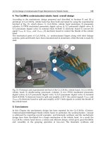
ExpandingtheScopeofInstantMessagingwithBidirectionalHapticCommunication 583
Expanding the Scope of Instant Messaging with Bidirectional Haptic
Communication
YoungjaeKimandMinsooHahn
X
Expanding the Scope of Instant Messaging
with Bidirectional Haptic Communication
Youngjae Kim and Minsoo Hahn
Korea Advanced Institute of Science and Technology
Korea, Republic of
1. Introduction
For the past five years, haptic interfaces have been applied to various commercial products.
Most consumers are now familiar with the term haptic. Many among them use vibro-tactile
feedback equipped touchscreen devices, although they may not have a clear understanding
of what it is. According to the Google Trend result (
Korean people type in and search for the keyword haptic more frequently than people in
other countries. The traffic gaps between Korea and other countries are as follows.
Region Traffic std error City Traffic std error
South Korea 1 0% Seoul (South Korea) 1 0%
Vietnam 0.475 5% Singapore (Singapore) 0.435 5%
Singapore 0.395 5% Jakarta (Indonesia) 0.22 10%
Malaysia 0.25 5% Ottawa (Canada) 0.21 10%
Philippines 0.23 5% Bangkok (Thailand) 0.2 10%
Thailand 0.195 5% Hong Kong (Hong Kong) 0.175 10%
Indonesia 0.18 10% Delhi (India) 0.115 10%
Hong Kong 0.18 10% Seattle (USA) 0.115 10%
Taiwan 0.145 5% San Francisco (USA) 0.115 10%
India 0.14 5% Los Angeles (USA) 0.11 10%
Table 1. Google Trend result on the keyword haptic (data acquired on Aug. 31, 2009)
In Table 1, the numbers in the Traffic column represent the relative values calculated upon
the most dominant region (in this case, South Korea). As can be seen in Table 1, the search
traffic of South Korea is twice higher than those of other countries such as Vietnam,
Singapore, and the USA. It is mainly due to the marketing strategy of local cellular phone
manufacturers that included the term haptic in their product names. The important point is
not only that people are becoming familiar with the keyword, but also that many research
and industry fields are starting to focus on haptic and its effects. For example, a car
manufacturer may try to apply a haptic interface to the navigation controller, or a bank may
introduce ATM’s with a newly installed haptic feedback-equipped touchscreen. In short,
haptic technology is making gradual changes in our daily lifestyle.
31
AdvancesinHaptics584
The initial goal of haptic technology is to facilitate the manipulation of devices. A vibro-tactile
feedback enables a user to control a device more accurately and easily. For the next step, haptic
aims to give intuitiveness to control target devices. This is mainly because, from a cognitive
point of view, users expect a kind of reaction if he or she tries to command to the target.
Haptic technologies are widely employed in many areas these days, but in this chapter, we
will focus on its communication usage only. As shown in many studies, haptic can be a type
of daily messaging behaviours. Computer-mediated messaging technologies continue to
evolve rapidly, and various types of messaging services are being marketed including short
message services (SMS’s) provided on a cellular phone, message-oriented networking
services such as Twitter (Java et al. 2007), blogs with trackback and reply systems, and
instant messenger applications that enable peer-to-peer communication in real-time. More
innovative types of messaging will continue to emerge (Poupyrev, Nashida, and Okabe
2007). Regardless of the type of messaging, all services share a common goal of diversifying
communications among people (Vilhjálmsson 2003). This study aims to improve messaging
experiences more realistic by adding a framework for haptic interaction.
The term haptic means pertaining to the sense of touch, and thus haptic communication can be
described as “communicating via touching”. Bonanni had an insight into this concept and
tried to implement it (Bonanni et al. 2006). He had studied the way to convey sensations from
peer to peer. Rovers had introduced the vibro-tactile-pattern-embedded emoticon named HIM
(A. F. Rovers and Van Essen 2004). His research method is quite similar to that proposed in
this chapter. The vibro-tactile pattern is embedded into an emoticon so that users can feel more
realistic sensations while engaged in instant messaging. VibeTonz (Immersion Corp 2007) is a
commercialized vibro-tactile composer from Immersion. As a cellular phone with a touch
screen or a conductive switch is being produced by a number of manufacturers these days,
Immersion’s VibeTonz technology is actively employed. VibeTonz can compose tactile output
patterns along with a timeline. Although many researches led to touch-enabled emoticons
(Chang et al. 2002; L. Rovers and Van Essen 2004; Aleven et al. 2006), most of these researches
were limited to conveying vibro-tactile actuation. The component of touch and related
sensations encompass not only tactile stimulus, but also temperature, sound, etc. For this
reason, a framework to send and to receive the whole spectrum of haptic is strongly required.
The objective of this research is to facilitate haptic communications among users and expand
the scope of the computer-mediated conversation.
The bidirectional haptic means that a sensor and an actuator can be manipulated on a single
framework. This is a simple concept, but most researches tend to focus on one side only. To
achieve true haptic communication, a system providing both a sensor and an actuator
within a single framework is needed. Brave introduced in-Touch (Brave and Dahley 1997) to
synchronize each cylinder-like device. Two devices are connected and have both a sensor
and an actuator in one single tangible object. When one user rolls one device, the motor in
the other part starts to run. HAML (El-Far et al. 2006) is a haptic markup language which
centers on the haptic description. This is a technical specification that tries to elevate to the
MPEG standards. In this research, the Phantom device is mainly applied. HAMLET
(Mohamad Eid et al. 2008) is a HAML-based authoring tool. Both HAMLET and this
research aim to accomplish simplicity and efficiency in utilizing haptic for non-programmer
developers and artists. However, our target users are rather general users than those of
HAMLET, who uses the instant messenger as a daily communication tool. From the view of
the description language, or the markup language, SensorML (Botts and Robin 2007) is one
of the specifications to describe a sensor. The object of this markup language is to provide
the sensor information as detailed as possible including the manufacturer, hardware
specifications, the data type to acquire a result, etc. It can be adopted into our work, but we
concluded it is too verbose to apply this SensorML to our work.
In this study, TouchCon, a next-generation emoticon for haptic-embedded communication,
is proposed. The architecture of the framework to represent haptic expressions in our daily
messaging and chatting is also provided. In addition, included is the hardware specially
designed for testing and the summary of user preference surveys with reference to the
previous researches (Kim et al. 2009; Kim et al. 2009; Shin et al. 2007).
2. A Platform for Managing Haptic Communication
2.1 Overall Description
The proposed system enables a user to manipulate haptic interaction and to share it with
others. To achieve this goal, we need to summarize the requirements of the system. The
system needs to support haptic actuator control, sensor data acquisition, linkage with
various applications, library management, etc. One important goal of this study is to resolve
the haptic expression even when two devices are not identical.
For this reason, the haptic communication framework has been designed to achieve the
flexibility and the scalability. The flexibility allows the framework to invite and to
manipulate different devices. To support haptic-enabled hardwares, the framework must be
capable of providing a standardized gateway. Thus, the architecture adopted here has a
similar goal to the middleware system (Baldauf, Dustdar, and Rosenberg 2007) from the
architectural point of view. The scalability means, the framework is extensible to adopt
various sensors and actuators according to their descriptions. For that, the framework has to
allow various protocols. Figure 1 shows the overall architecture of the platform.
Fig. 1. Overall TouchCon architecture
ExpandingtheScopeofInstantMessagingwithBidirectionalHapticCommunication 585
The initial goal of haptic technology is to facilitate the manipulation of devices. A vibro-tactile
feedback enables a user to control a device more accurately and easily. For the next step, haptic
aims to give intuitiveness to control target devices. This is mainly because, from a cognitive
point of view, users expect a kind of reaction if he or she tries to command to the target.
Haptic technologies are widely employed in many areas these days, but in this chapter, we
will focus on its communication usage only. As shown in many studies, haptic can be a type
of daily messaging behaviours. Computer-mediated messaging technologies continue to
evolve rapidly, and various types of messaging services are being marketed including short
message services (SMS’s) provided on a cellular phone, message-oriented networking
services such as Twitter (Java et al. 2007), blogs with trackback and reply systems, and
instant messenger applications that enable peer-to-peer communication in real-time. More
innovative types of messaging will continue to emerge (Poupyrev, Nashida, and Okabe
2007). Regardless of the type of messaging, all services share a common goal of diversifying
communications among people (Vilhjálmsson 2003). This study aims to improve messaging
experiences more realistic by adding a framework for haptic interaction.
The term haptic means pertaining to the sense of touch, and thus haptic communication can be
described as “communicating via touching”. Bonanni had an insight into this concept and
tried to implement it (Bonanni et al. 2006). He had studied the way to convey sensations from
peer to peer. Rovers had introduced the vibro-tactile-pattern-embedded emoticon named HIM
(A. F. Rovers and Van Essen 2004). His research method is quite similar to that proposed in
this chapter. The vibro-tactile pattern is embedded into an emoticon so that users can feel more
realistic sensations while engaged in instant messaging. VibeTonz (Immersion Corp 2007) is a
commercialized vibro-tactile composer from Immersion. As a cellular phone with a touch
screen or a conductive switch is being produced by a number of manufacturers these days,
Immersion’s VibeTonz technology is actively employed. VibeTonz can compose tactile output
patterns along with a timeline. Although many researches led to touch-enabled emoticons
(Chang et al. 2002; L. Rovers and Van Essen 2004; Aleven et al. 2006), most of these researches
were limited to conveying vibro-tactile actuation. The component of touch and related
sensations encompass not only tactile stimulus, but also temperature, sound, etc. For this
reason, a framework to send and to receive the whole spectrum of haptic is strongly required.
The objective of this research is to facilitate haptic communications among users and expand
the scope of the computer-mediated conversation.
The bidirectional haptic means that a sensor and an actuator can be manipulated on a single
framework. This is a simple concept, but most researches tend to focus on one side only. To
achieve true haptic communication, a system providing both a sensor and an actuator
within a single framework is needed. Brave introduced in-Touch (Brave and Dahley 1997) to
synchronize each cylinder-like device. Two devices are connected and have both a sensor
and an actuator in one single tangible object. When one user rolls one device, the motor in
the other part starts to run. HAML (El-Far et al. 2006) is a haptic markup language which
centers on the haptic description. This is a technical specification that tries to elevate to the
MPEG standards. In this research, the Phantom device is mainly applied. HAMLET
(Mohamad Eid et al. 2008) is a HAML-based authoring tool. Both HAMLET and this
research aim to accomplish simplicity and efficiency in utilizing haptic for non-programmer
developers and artists. However, our target users are rather general users than those of
HAMLET, who uses the instant messenger as a daily communication tool. From the view of
the description language, or the markup language, SensorML (Botts and Robin 2007) is one
of the specifications to describe a sensor. The object of this markup language is to provide
the sensor information as detailed as possible including the manufacturer, hardware
specifications, the data type to acquire a result, etc. It can be adopted into our work, but we
concluded it is too verbose to apply this SensorML to our work.
In this study, TouchCon, a next-generation emoticon for haptic-embedded communication,
is proposed. The architecture of the framework to represent haptic expressions in our daily
messaging and chatting is also provided. In addition, included is the hardware specially
designed for testing and the summary of user preference surveys with reference to the
previous researches (Kim et al. 2009; Kim et al. 2009; Shin et al. 2007).
2. A Platform for Managing Haptic Communication
2.1 Overall Description
The proposed system enables a user to manipulate haptic interaction and to share it with
others. To achieve this goal, we need to summarize the requirements of the system. The
system needs to support haptic actuator control, sensor data acquisition, linkage with
various applications, library management, etc. One important goal of this study is to resolve
the haptic expression even when two devices are not identical.
For this reason, the haptic communication framework has been designed to achieve the
flexibility and the scalability. The flexibility allows the framework to invite and to
manipulate different devices. To support haptic-enabled hardwares, the framework must be
capable of providing a standardized gateway. Thus, the architecture adopted here has a
similar goal to the middleware system (Baldauf, Dustdar, and Rosenberg 2007) from the
architectural point of view. The scalability means, the framework is extensible to adopt
various sensors and actuators according to their descriptions. For that, the framework has to
allow various protocols. Figure 1 shows the overall architecture of the platform.
Fig. 1. Overall TouchCon architecture
AdvancesinHaptics586
The platform consists of three main parts; the core, the library, and the hardware. The core is
a runtime to execute haptic interactions. The library handles haptic emoticons and their
patterns, and the hardware deals with controllable hardwares. Before moving on to
elaborate on each component, it must be explained that an action stands for a single motion
of haptic.
Each module is described in Table 2.
Component Name Description
TouchCon Core Runtime of the framework
TouchCon Library A list of TouchCons and a TouchCon, which is composed by a user or
a ha
p
tic emoticon distributor
TouchCon Device A hardware management of a TouchCon device (generally an actuator
or a sensor
)
Librar
y
XML file An XML file which stores com
p
osed TouchCons
Device XML file An XML file which stores hardware protocol specifications and
acce
p
table
comma
n
ds
Connection Interface Methods of communication through TouchCon hardware.
Table 2. Component description
To ensure the flexibility, we discriminate the library from the hardware at first. This allows
for the framework to actuate similar haptic expressions with different hardware
specifications. For example, there is only one red-coloured LED in the current hardware, the
received TouchCon action could request to actuate the vibration motor. In this case, the
resolver needs to interpret the TouchCon action into similar haptic expressions with current
hardware specifications. In architectural point of view, if the hardware is directly coupled
with the library and able to activate the identical hardware only, haptic expressions are
limited to the hardware. To address this problem, the core runtime activates a function, i.e.,
the resolver, that interprets haptic expressions in accordance with hardware functionalities.
The hardware monitors each available sensor and actuator so that the library acquires
needed information to utilize them. For this reason, hardware management is relatively
simpler than that of the library and the core in the framework.
2.2 TouchCon Core
The TouchCon Core consists of three components; the runtime to execute the library, the
resolver to support different hardwares, and the sensor manager. The runtime module
commands each haptic action to the hardware at every millisecond. In other words, a haptic
action can be controlled in one millisecond. The runtime acts one of three behaviors with given
TouchCon; activate user’s hardware, transmit a TouchCon to a peer, or do nothing.
The resolver component modifies the input haptic action command when the hardware
mismatch occurs. In other words, it compromises current hardware specifications and the
input haptic expressions. Thanks to this resolver, the library can send TouchCon actions to the
hardware as suitable as possible regardless of the type of the hardware attached to the user’s
device. The details of the resolver are given in Section 4.2.
The sensor manager processes the sensor input data. Unlike a general hardware management
approach, the sensor management is done by the TouchCon Core. The reason why the sensor
is considered as the core component and not as the hardware one is that a sensor requires to
process the acquired data. For example, the user can send a ‘smile’ haptic action as his/her
laughing sound. Namely, the microphone can act as an input sensor to the framework and this
is one of the useful scenarios in our work. In short, the input expression needs a decision to be
described and sent as a TouchCon action format.
2.3 TouchCon Library
The TouchCon Library is a bundle of TouchCon actions. It can have one or more TouchCons
according to the haptic expression. The library consists of three components; the TouchCon
Library manager for organizing TouchCons, the in-memory database for storing temporary
TouchCon actions, and the API (Application Programming Interface) for upper level
applications. The TouchCon Library manager includes an XML parser to encode and to
decode the given TouchCons with the TouchCon Library schema. Since all data handled in our
work are designed to use the XML only, haptic contents can be authored with no length
limitation. The specification of the schema and its example are given in the next section. The
API allows external applications such as an instant messenger or the internet browser to
communicate with the haptic framework. Unlike commonly used API approaches, our work is
coupled with hardwares. For this reason, the API restricts to be invoked by one application
only. If this restriction does not exist, the hardware might be collided by commands from
multiple applications.
2.4 TouchCon Hardware
Since the scope of this study is not restricted to the vibro-tactile actuation, the hardware
component can invite different protocols. Moreover, as haptic-enabled hardwares are being
produced by various manufacturers, the framework should have a room to support them. If
these future changes are not taken into consideration and thus only the limited haptic
expressions can be executable, the results of this study may not be applicable in the near
future. One of the possible solutions is to adopt an abstract layer above the hardware driver
layer, and to simplify the hardware types and the commands. These approaches are used in
Microsoft Windows HAL (Hardware Abstraction Layer) architecture and JINI home
network one(Arnold et al. 1999; Russinovich and Solomon 2005). Once the hardware is
attached to the framework, the abstract layer loads small description files and organizes
available functionalities. In general, the hardware description files are located in the web or
a local system. The advantage of this approach is to provide unified control points to other
applications and to enable to invite various types of haptic-enabled hardwares.
Same approach is applied to our work. Once the device is connected and the description file,
we call TouchCon Device XML, is loaded successfully, the TouchCon Device Manager
expects the runtime to give some commands.
3. Haptic Description Language
We design two haptic description XML schemas in order to manage haptic commands and
to activate haptic-enabled hardwares. Three factors must be taken into consideration to
design schemas.
ExpandingtheScopeofInstantMessagingwithBidirectionalHapticCommunication 587
The platform consists of three main parts; the core, the library, and the hardware. The core is
a runtime to execute haptic interactions. The library handles haptic emoticons and their
patterns, and the hardware deals with controllable hardwares. Before moving on to
elaborate on each component, it must be explained that an action stands for a single motion
of haptic.
Each module is described in Table 2.
Component Name Description
TouchCon Core Runtime of the framework
TouchCon Library A list of TouchCons and a TouchCon, which is composed by a user or
a ha
p
tic emoticon distributor
TouchCon Device A hardware management of a TouchCon device (generally an actuator
or a sensor
)
Librar
y
XML file An XML file which stores com
p
osed TouchCons
Device XML file An XML file which stores hardware protocol specifications and
acce
p
table
comma
n
ds
Connection Interface Methods of communication through TouchCon hardware.
Table 2. Component description
To ensure the flexibility, we discriminate the library from the hardware at first. This allows
for the framework to actuate similar haptic expressions with different hardware
specifications. For example, there is only one red-coloured LED in the current hardware, the
received TouchCon action could request to actuate the vibration motor. In this case, the
resolver needs to interpret the TouchCon action into similar haptic expressions with current
hardware specifications. In architectural point of view, if the hardware is directly coupled
with the library and able to activate the identical hardware only, haptic expressions are
limited to the hardware. To address this problem, the core runtime activates a function, i.e.,
the resolver, that interprets haptic expressions in accordance with hardware functionalities.
The hardware monitors each available sensor and actuator so that the library acquires
needed information to utilize them. For this reason, hardware management is relatively
simpler than that of the library and the core in the framework.
2.2 TouchCon Core
The TouchCon Core consists of three components; the runtime to execute the library, the
resolver to support different hardwares, and the sensor manager. The runtime module
commands each haptic action to the hardware at every millisecond. In other words, a haptic
action can be controlled in one millisecond. The runtime acts one of three behaviors with given
TouchCon; activate user’s hardware, transmit a TouchCon to a peer, or do nothing.
The resolver component modifies the input haptic action command when the hardware
mismatch occurs. In other words, it compromises current hardware specifications and the
input haptic expressions. Thanks to this resolver, the library can send TouchCon actions to the
hardware as suitable as possible regardless of the type of the hardware attached to the user’s
device. The details of the resolver are given in Section 4.2.
The sensor manager processes the sensor input data. Unlike a general hardware management
approach, the sensor management is done by the TouchCon Core. The reason why the sensor
is considered as the core component and not as the hardware one is that a sensor requires to
process the acquired data. For example, the user can send a ‘smile’ haptic action as his/her
laughing sound. Namely, the microphone can act as an input sensor to the framework and this
is one of the useful scenarios in our work. In short, the input expression needs a decision to be
described and sent as a TouchCon action format.
2.3 TouchCon Library
The TouchCon Library is a bundle of TouchCon actions. It can have one or more TouchCons
according to the haptic expression. The library consists of three components; the TouchCon
Library manager for organizing TouchCons, the in-memory database for storing temporary
TouchCon actions, and the API (Application Programming Interface) for upper level
applications. The TouchCon Library manager includes an XML parser to encode and to
decode the given TouchCons with the TouchCon Library schema. Since all data handled in our
work are designed to use the XML only, haptic contents can be authored with no length
limitation. The specification of the schema and its example are given in the next section. The
API allows external applications such as an instant messenger or the internet browser to
communicate with the haptic framework. Unlike commonly used API approaches, our work is
coupled with hardwares. For this reason, the API restricts to be invoked by one application
only. If this restriction does not exist, the hardware might be collided by commands from
multiple applications.
2.4 TouchCon Hardware
Since the scope of this study is not restricted to the vibro-tactile actuation, the hardware
component can invite different protocols. Moreover, as haptic-enabled hardwares are being
produced by various manufacturers, the framework should have a room to support them. If
these future changes are not taken into consideration and thus only the limited haptic
expressions can be executable, the results of this study may not be applicable in the near
future. One of the possible solutions is to adopt an abstract layer above the hardware driver
layer, and to simplify the hardware types and the commands. These approaches are used in
Microsoft Windows HAL (Hardware Abstraction Layer) architecture and JINI home
network one(Arnold et al. 1999; Russinovich and Solomon 2005). Once the hardware is
attached to the framework, the abstract layer loads small description files and organizes
available functionalities. In general, the hardware description files are located in the web or
a local system. The advantage of this approach is to provide unified control points to other
applications and to enable to invite various types of haptic-enabled hardwares.
Same approach is applied to our work. Once the device is connected and the description file,
we call TouchCon Device XML, is loaded successfully, the TouchCon Device Manager
expects the runtime to give some commands.
3. Haptic Description Language
We design two haptic description XML schemas in order to manage haptic commands and
to activate haptic-enabled hardwares. Three factors must be taken into consideration to
design schemas.
AdvancesinHaptics588
- Scalability: To include an abundance of haptic interactions and to support a combination of
sensors and actuators, scalability must be considered in the system. This is the main reason
why the XML format is adopted in this study.
- Flexibility: In this study, flexibility stands for adaptability. This means the schema can
describe any form of the hardware interface. To incorporated with the framework, the
developer must follow the suggested guidelines, but the developer’s effort for the
adaptation is minimized.
- Readability: According to Norman (Norman 2002), intuitiveness is an important factor in
modern technology. From the view of consumer products, intuitiveness means easy-to-
understand, easy-to-manipulate, and easy-to-use. Likewise, the schemas in this study have
been carefully designed to be understood by general users as easy as possible. For example,
the SensorML schemas that describe hardware specifications tend to be highly complicated
because these formats are made to achieve more complex goals; to describe every kind of
sensors in full details. Besides, our schemas require to describe the basic profile, the
command list, and the data type only.
3.1 XML Schema for Haptic Device Description
As we introduced in Section 2.4, the objective of the device description is to incorporate
various types of haptic-enabled hardwares together. To ensure the bidirectional haptic
communication, both the sensor and the actuator must be described in a single schema. The
method we use is to put the ‘Output’ attribute to each device description. The ‘Output’
attribute is allocated as a Boolean data type. If it sets to True, it indicates an actuator.
Otherwise, it is a sensor. Even though the framework separates the sensor manager from the
device manager (see Figure 1), the combination of sensors and hardwares in a schema is
reasonable in the sense of bidirectional haptic. The details of the TouchCon device schema are
summarized in Table 3. Note that the word ‘TCon’ is an abbreviation of TouchCon. As can
be seen in this table, we designed it with less mandatory attributes.
Name Attributes
TConDevices (optional)
Description: specifications or vendor information
TConDevice
(mandatory)
Name: name of the controllable device
Output: Boolean value for indicating sensor or actuator
DataType: Property for protocol
(optional)
Description: information of the component
Property (mandatory)
Name: name to be displayed on the component
Start: Start command
End: End command
Table 3. Description on the haptic device schema
As can be seen in Table 3, we designed it with less mandatory attributes. Note that the word
TCon is an abbreviation of TouchCon. The example using the schema is in Figure 2.
Fig. 2. Example of the TouchCon device description
Figure 2 shows an example of the TouchCon Device XML schema. The root ‘TConDevices’
can contain multiple ‘TConDevice’ tags and one ‘TConDevice’ tag can contain multiple
‘Property’ tags. To understand the meaning of the example in Figure 2, we can see three
actuators are involved in the framework; Upper Lip at line 3, Pin at line 13, and Heat at line
19. And also, we can identify that all three hardwares act as actuators from Output attributes.
The values of each Start and End attributes inside the TConDevice tags are the unique
commands for hardwares. These commands are totally dependent on the developer’s
hardwares. Currently, only ASCII strings are allowed to be used as commands.
3.2 XML Schema for Action Description
Unlike traditional text-based emoticons, the big changes in multimedia-enabled and haptic-
embedded emoticons are able to deliver timeline-based actions. For example, a multimedia-
enabled emoticon can play a small size animation with music. A haptic-embedded emoticon,
the next generation of the emoticon, has additional features along with the timeline; a
triggered hardware, its duration, and its property to be activated at each moment.
The TouchCon Action is a single element of hardware activation. And TouchCon Library is
a bundle of actions. One action describes the device to be activated and its activation time.
This is very similar to the music score. In other words, the TouchCon Library schema is the
rule to write a score regarding haptic. Table 4 describes the schema of TouchCon Library
and Action.
ExpandingtheScopeofInstantMessagingwithBidirectionalHapticCommunication 589
- Scalability: To include an abundance of haptic interactions and to support a combination of
sensors and actuators, scalability must be considered in the system. This is the main reason
why the XML format is adopted in this study.
- Flexibility: In this study, flexibility stands for adaptability. This means the schema can
describe any form of the hardware interface. To incorporated with the framework, the
developer must follow the suggested guidelines, but the developer’s effort for the
adaptation is minimized.
- Readability: According to Norman (Norman 2002), intuitiveness is an important factor in
modern technology. From the view of consumer products, intuitiveness means easy-to-
understand, easy-to-manipulate, and easy-to-use. Likewise, the schemas in this study have
been carefully designed to be understood by general users as easy as possible. For example,
the SensorML schemas that describe hardware specifications tend to be highly complicated
because these formats are made to achieve more complex goals; to describe every kind of
sensors in full details. Besides, our schemas require to describe the basic profile, the
command list, and the data type only.
3.1 XML Schema for Haptic Device Description
As we introduced in Section 2.4, the objective of the device description is to incorporate
various types of haptic-enabled hardwares together. To ensure the bidirectional haptic
communication, both the sensor and the actuator must be described in a single schema. The
method we use is to put the ‘Output’ attribute to each device description. The ‘Output’
attribute is allocated as a Boolean data type. If it sets to True, it indicates an actuator.
Otherwise, it is a sensor. Even though the framework separates the sensor manager from the
device manager (see Figure 1), the combination of sensors and hardwares in a schema is
reasonable in the sense of bidirectional haptic. The details of the TouchCon device schema are
summarized in Table 3. Note that the word ‘TCon’ is an abbreviation of TouchCon. As can
be seen in this table, we designed it with less mandatory attributes.
Name Attributes
TConDevices (optional)
Description: specifications or vendor information
TConDevice
(mandatory)
Name: name of the controllable device
Output: Boolean value for indicating sensor or actuator
DataType: Property for protocol
(optional)
Description: information of the component
Property (mandatory)
Name: name to be displayed on the component
Start: Start command
End: End command
Table 3. Description on the haptic device schema
As can be seen in Table 3, we designed it with less mandatory attributes. Note that the word
TCon is an abbreviation of TouchCon. The example using the schema is in Figure 2.
Fig. 2. Example of the TouchCon device description
Figure 2 shows an example of the TouchCon Device XML schema. The root ‘TConDevices’
can contain multiple ‘TConDevice’ tags and one ‘TConDevice’ tag can contain multiple
‘Property’ tags. To understand the meaning of the example in Figure 2, we can see three
actuators are involved in the framework; Upper Lip at line 3, Pin at line 13, and Heat at line
19. And also, we can identify that all three hardwares act as actuators from Output attributes.
The values of each Start and End attributes inside the TConDevice tags are the unique
commands for hardwares. These commands are totally dependent on the developer’s
hardwares. Currently, only ASCII strings are allowed to be used as commands.
3.2 XML Schema for Action Description
Unlike traditional text-based emoticons, the big changes in multimedia-enabled and haptic-
embedded emoticons are able to deliver timeline-based actions. For example, a multimedia-
enabled emoticon can play a small size animation with music. A haptic-embedded emoticon,
the next generation of the emoticon, has additional features along with the timeline; a
triggered hardware, its duration, and its property to be activated at each moment.
The TouchCon Action is a single element of hardware activation. And TouchCon Library is
a bundle of actions. One action describes the device to be activated and its activation time.
This is very similar to the music score. In other words, the TouchCon Library schema is the
rule to write a score regarding haptic. Table 4 describes the schema of TouchCon Library
and Action.
AdvancesinHaptics590
Name Attributes
TCons (optional)
User: name of the author
TCon (mandatory)
Name: Name of the TouchCon action
(optional)
Image: small icon to display with the haptic action.
Speed: running speed to be executed in the runtime component
Description: information of the TouchCon.
Action (mandatory)
Device: Name of the device to be actuated
StartTime: Start time in millisecond
Duration: Duration time to play in millisecond
(optional)
Property: One of the device command
Table 4. Description on the haptic library schema
Figure 3 below shows an example of the TouchCon Library schemas in Table 4. According
to Table 4, the library here has three levels of depth. We design the schema to have the
minimum depth with many attributes, because the XML parser tends to slow down when
the depth increases.
Fig. 3. Example of the haptic device description
In contrast to the TouchCon Device schema, the TouchCon Library one is for users, not for
developers. As we can see in Figure 3, one TouchCon Library (TCons) can contain one or
more TouchCon Actions (TCon tags). And one TouchCon Action has a list of commands and
times.
A single TouchCon Action can be represented as one haptic emoticon. Thus, it can be played
on the user’s hardware or sent to the peer’s one.
3.3 TouchCon XML Parser
As all TouchCon-based data are handled and delivered in the XML format, the XML parser
is installed in the framework. The TouchCon parser encodes and decodes TouchCon data;
the TouchCon Library, included actions, sensor specifications, and hardware descriptions.
Once the TouchCon parser receives TouchCon Action data, it loads the data in the in-
memory database in the FIFO manner. The in-memory database is an array-list so that it is
expandable. There are pros and cons to make the in-memory data structure and the XML
structure identical. Firstly, the pros; it has to be easy to convert, simple to understand for the
user (or the developer), and easy to allocate for very large data. Now, the cons; it tends to
cause memory abuse because of the unused TouchCon data, and it leads to the rather long
processing time to be allocated into memory. Only two XML schemas were used in our
framework, but the implemented TouchCon parser requires to interpret four types of XML
data structures; TouchCon Library, TouchCon Action, TouchCon Device, and TouchCon
sensor. One reason is that the Library is not just a bundle of actions, but additional
information exists. And the other reason is the device and sensors are designed to share the
same format for the realization of the bidirectional haptic concept (see Section 3.1), but from
the view of the parser, they are not handled in the same way. In short, the two schemas are
implemented to four structures.
4. Haptic Composer
This chapter introduces the Haptic Editor and the Haptic Resolver. Both aim to enhance the
usefulness of the proposed framework. The Haptic Editor is a WYSIWYG editor with
attached haptic hardwares. The Haptic Resolver is one of the modules in the TouchCon Core
(see Figure 1), which negotiates haptic actuations when two corresponding peers use
different hardwares.
4.1 Haptic Editor
The Haptic Editor is a timeline-based TouchCon editing tool. Today, many computer-savvy
users are familiar with timeline-based multimedia editing tools such as Microsoft
MovieMaker or Adobe Flash. Apart from the previous works (Aleven et al. 2006; Mohamad
Eid et al. 2008), our Haptic Editor was designed in a WISIWIG manner. Basically, such a tool
consists of two core parts; the horizontal part stands for time and the vertical part stands for
elements. Timeline is labeled horizontally and elements are arranged vertically. Logically,
the timeline and the involved elements are unlimited. Similar to common multimedia
editing tools, our system is trigger-based one. Namely, each action is activated after the
running time is passed at the designated moment.
ExpandingtheScopeofInstantMessagingwithBidirectionalHapticCommunication 591
Name Attributes
TCons (optional)
User: name of the author
TCon (mandatory)
Name: Name of the TouchCon action
(optional)
Image: small icon to display with the haptic action.
Speed: running speed to be executed in the runtime component
Description: information of the TouchCon.
Action (mandatory)
Device: Name of the device to be actuated
StartTime: Start time in millisecond
Duration: Duration time to play in millisecond
(optional)
Property: One of the device command
Table 4. Description on the haptic library schema
Figure 3 below shows an example of the TouchCon Library schemas in Table 4. According
to Table 4, the library here has three levels of depth. We design the schema to have the
minimum depth with many attributes, because the XML parser tends to slow down when
the depth increases.
Fig. 3. Example of the haptic device description
In contrast to the TouchCon Device schema, the TouchCon Library one is for users, not for
developers. As we can see in Figure 3, one TouchCon Library (TCons) can contain one or
more TouchCon Actions (TCon tags). And one TouchCon Action has a list of commands and
times.
A single TouchCon Action can be represented as one haptic emoticon. Thus, it can be played
on the user’s hardware or sent to the peer’s one.
3.3 TouchCon XML Parser
As all TouchCon-based data are handled and delivered in the XML format, the XML parser
is installed in the framework. The TouchCon parser encodes and decodes TouchCon data;
the TouchCon Library, included actions, sensor specifications, and hardware descriptions.
Once the TouchCon parser receives TouchCon Action data, it loads the data in the in-
memory database in the FIFO manner. The in-memory database is an array-list so that it is
expandable. There are pros and cons to make the in-memory data structure and the XML
structure identical. Firstly, the pros; it has to be easy to convert, simple to understand for the
user (or the developer), and easy to allocate for very large data. Now, the cons; it tends to
cause memory abuse because of the unused TouchCon data, and it leads to the rather long
processing time to be allocated into memory. Only two XML schemas were used in our
framework, but the implemented TouchCon parser requires to interpret four types of XML
data structures; TouchCon Library, TouchCon Action, TouchCon Device, and TouchCon
sensor. One reason is that the Library is not just a bundle of actions, but additional
information exists. And the other reason is the device and sensors are designed to share the
same format for the realization of the bidirectional haptic concept (see Section 3.1), but from
the view of the parser, they are not handled in the same way. In short, the two schemas are
implemented to four structures.
4. Haptic Composer
This chapter introduces the Haptic Editor and the Haptic Resolver. Both aim to enhance the
usefulness of the proposed framework. The Haptic Editor is a WYSIWYG editor with
attached haptic hardwares. The Haptic Resolver is one of the modules in the TouchCon Core
(see Figure 1), which negotiates haptic actuations when two corresponding peers use
different hardwares.
4.1 Haptic Editor
The Haptic Editor is a timeline-based TouchCon editing tool. Today, many computer-savvy
users are familiar with timeline-based multimedia editing tools such as Microsoft
MovieMaker or Adobe Flash. Apart from the previous works (Aleven et al. 2006; Mohamad
Eid et al. 2008), our Haptic Editor was designed in a WISIWIG manner. Basically, such a tool
consists of two core parts; the horizontal part stands for time and the vertical part stands for
elements. Timeline is labeled horizontally and elements are arranged vertically. Logically,
the timeline and the involved elements are unlimited. Similar to common multimedia
editing tools, our system is trigger-based one. Namely, each action is activated after the
running time is passed at the designated moment.
AdvancesinHaptics592
Fig. 4. Haptic Editor
Figure 4 shows a screenshot of the TouchCon Editor. This editor was designed to compose
TouchCon Actions and to save them in the TouchCon Library file. The vertical layers
indicate available (or controllable) haptic hardwares while the horizontal bars, durations of
each action. The text label in the middle of the duration bar is for the property of the
hardware. For example as in Figure 4, the label ‘Red’ indicates the light color of the LED.
The ‘Preview’ button at the bottom of the window executes (or plays) the current actions
and activates the connected hardwares in order to test the composed results. When the user
finishes making his/her own TouchCon Actions, the only thing to do is to click the ‘Done’
button to save the TouchCon haptic actions. Once the button is clicked, a popup window
(save dialog) appears in order to incorporate a thumbnail image or additional descriptions.
Fig. 5. Architecture of the Haptic Editor
Figure 5 illustrates how the Haptic Editor is constructed. The TouchCon framework
communicates with a microcontroller through the RS232 serial port. The RS232 serial port
can be replaced by the USB or the Bluetooth interface. The ‘PIC Micom’ stands for the
Microchip® PIC microcontroller. We use an 8 bit microcontroller as the default, but the
developer can use any type of microcontroller as far as the developer provides a proper
TouchCon Device file.
As we can see in the middle (the orange-colored box), the Haptic Editor also uses the API of
the TouchCon framework. The API allows the editor to create, append, remove, and arrange
TouchCon Actions. The sensor is handled by the sensor manager. With the sensor data, the
sensor manager executes one of three activities; activate user’s hardwares, transmit a
TouchCon to a peer, or do nothing. The decision along with the value from the sensor has to
be defined in the TouchCon Action. Currently, the sensor-related implementation available
in our work is only the rule-based decision. For instance, the 0-255 analog value (or 8 bit
resolution) from a microcontroller can be categorized into three ranges and each range has
ExpandingtheScopeofInstantMessagingwithBidirectionalHapticCommunication 593
Fig. 4. Haptic Editor
Figure 4 shows a screenshot of the TouchCon Editor. This editor was designed to compose
TouchCon Actions and to save them in the TouchCon Library file. The vertical layers
indicate available (or controllable) haptic hardwares while the horizontal bars, durations of
each action. The text label in the middle of the duration bar is for the property of the
hardware. For example as in Figure 4, the label ‘Red’ indicates the light color of the LED.
The ‘Preview’ button at the bottom of the window executes (or plays) the current actions
and activates the connected hardwares in order to test the composed results. When the user
finishes making his/her own TouchCon Actions, the only thing to do is to click the ‘Done’
button to save the TouchCon haptic actions. Once the button is clicked, a popup window
(save dialog) appears in order to incorporate a thumbnail image or additional descriptions.
Fig. 5. Architecture of the Haptic Editor
Figure 5 illustrates how the Haptic Editor is constructed. The TouchCon framework
communicates with a microcontroller through the RS232 serial port. The RS232 serial port
can be replaced by the USB or the Bluetooth interface. The ‘PIC Micom’ stands for the
Microchip® PIC microcontroller. We use an 8 bit microcontroller as the default, but the
developer can use any type of microcontroller as far as the developer provides a proper
TouchCon Device file.
As we can see in the middle (the orange-colored box), the Haptic Editor also uses the API of
the TouchCon framework. The API allows the editor to create, append, remove, and arrange
TouchCon Actions. The sensor is handled by the sensor manager. With the sensor data, the
sensor manager executes one of three activities; activate user’s hardwares, transmit a
TouchCon to a peer, or do nothing. The decision along with the value from the sensor has to
be defined in the TouchCon Action. Currently, the sensor-related implementation available
in our work is only the rule-based decision. For instance, the 0-255 analog value (or 8 bit
resolution) from a microcontroller can be categorized into three ranges and each range has
AdvancesinHaptics594
its own activity. Generally, 0-30 is set to ‘Do nothing’ because such a low intensity value
tends to be a noise.
Fig. 6. Instant messenger for testing
A simple type of an instant messenger is implemented. This program is applied to the
demonstration system and used for the evaluation and the survey. The demonstration and
its result data are given in section 5.1. In Figure 6, three window-based programs are
introduced. The left window is a chat window for the conversation among peers. Users can
send text messages, graphical emoticons, or TouchCons. The middle window lists up the
available TouchCons. This window is designed to be located nearby the chat window. The
user can switch between TouchCon Editor and the list by clicking ‘view’ button. Namely,
the user can easily create his/her own TouchCon while doing chat. Moreover, the
messenger automatically adds new TouchCon to the list if the receiver does not have the
TouchCon that the peer sends. Finally, the right window is a messenger server that shows
available peers on the network. Entire programs are coded in C# language and run on the
Windows XP operating system with the .Net Framework version 2.0.
4.2 Haptic Resolver
What happens if a peer sends TouchCons using a cellular phone and the other receives it
with a laptop which cannot activate the received TouchCons? To solve this problem, the
platform has to resolve this discrepancy and modifies the TouchCons from the sender to the
acceptable and similar ones at the receiver.
Next is a simple example of the Haptic Resolver. At first, the magnitude of a TouchCon
Action is analyzed. The three attributes to activate haptic actuators are the frequency, the
amplitude, and the duration. Based on these, we can represent waveforms or the PWM
(Pulse Width Modulation) signals accurately. We found that the waveform is very similar to
sound signals. Thus, we utilize this metaphor to convert TouchCons or emoticons to haptic
actuator signals through the resolver. Figure 7 shows an example of this conversion.
Fig. 7. Sound signals and vibration mapping patterns
The upper part of each box shows recorded sounds of different sensations. During the
survey, subjects showed high preferences and high sensational sympathy for more than half
of the haptic expressions when the sound mapping is applied. The preference survey results
are described in Section 5.
5. Evaluation
To evaluate the proposed architecture, several hardware prototypes and software
applications are implemented. This chapter introduces how such prototypes and
applications work and how they can be utilized to expand the scope of human
communications.
5.1 Implementation of Haptic Testbed for Instant Messenger Environment
A hardware testbed with various actuators and sensors is implemented. The testbed is
designed for the instant messaging environment which is the main target of our system.
Industrial designers joined the project and proposed the idea of the palm-rest-shaped silicon
forms and a lip-shaped module to make a user feel more humane. The designer wants the
user to touch and feel the hardwares like a small pet. For that, the hardwares were covered
with the soft-feeling silicon material. In addition, we found that the silicon finish could
prevent the user from being injured by embedded heater units.
ExpandingtheScopeofInstantMessagingwithBidirectionalHapticCommunication 595
its own activity. Generally, 0-30 is set to ‘Do nothing’ because such a low intensity value
tends to be a noise.
Fig. 6. Instant messenger for testing
A simple type of an instant messenger is implemented. This program is applied to the
demonstration system and used for the evaluation and the survey. The demonstration and
its result data are given in section 5.1. In Figure 6, three window-based programs are
introduced. The left window is a chat window for the conversation among peers. Users can
send text messages, graphical emoticons, or TouchCons. The middle window lists up the
available TouchCons. This window is designed to be located nearby the chat window. The
user can switch between TouchCon Editor and the list by clicking ‘view’ button. Namely,
the user can easily create his/her own TouchCon while doing chat. Moreover, the
messenger automatically adds new TouchCon to the list if the receiver does not have the
TouchCon that the peer sends. Finally, the right window is a messenger server that shows
available peers on the network. Entire programs are coded in C# language and run on the
Windows XP operating system with the .Net Framework version 2.0.
4.2 Haptic Resolver
What happens if a peer sends TouchCons using a cellular phone and the other receives it
with a laptop which cannot activate the received TouchCons? To solve this problem, the
platform has to resolve this discrepancy and modifies the TouchCons from the sender to the
acceptable and similar ones at the receiver.
Next is a simple example of the Haptic Resolver. At first, the magnitude of a TouchCon
Action is analyzed. The three attributes to activate haptic actuators are the frequency, the
amplitude, and the duration. Based on these, we can represent waveforms or the PWM
(Pulse Width Modulation) signals accurately. We found that the waveform is very similar to
sound signals. Thus, we utilize this metaphor to convert TouchCons or emoticons to haptic
actuator signals through the resolver. Figure 7 shows an example of this conversion.
Fig. 7. Sound signals and vibration mapping patterns
The upper part of each box shows recorded sounds of different sensations. During the
survey, subjects showed high preferences and high sensational sympathy for more than half
of the haptic expressions when the sound mapping is applied. The preference survey results
are described in Section 5.
5. Evaluation
To evaluate the proposed architecture, several hardware prototypes and software
applications are implemented. This chapter introduces how such prototypes and
applications work and how they can be utilized to expand the scope of human
communications.
5.1 Implementation of Haptic Testbed for Instant Messenger Environment
A hardware testbed with various actuators and sensors is implemented. The testbed is
designed for the instant messaging environment which is the main target of our system.
Industrial designers joined the project and proposed the idea of the palm-rest-shaped silicon
forms and a lip-shaped module to make a user feel more humane. The designer wants the
user to touch and feel the hardwares like a small pet. For that, the hardwares were covered
with the soft-feeling silicon material. In addition, we found that the silicon finish could
prevent the user from being injured by embedded heater units.
AdvancesinHaptics596
Fig. 8. Design and development process
Figure 8 describes hardware products and their embedded components. At first, a
conceptual design was sketched. Then, sensors, actuators, and related circuits were placed
in consideration of the hand positions on the products. Later, PCB boards are installed
inside the specially designed foams.
Fig. 9. Actuators and sensors inserted into each hardware part
As can be seen in Figure 9, one animal-foot-shaped palm-rest component has one tactile
button, three pressure sensors, three vibration motors and one heater panel. The lip-shaped
compartment has ten RGB-color LEDs and one microphone. The microphone can detect the
user’s touch. Each foot-shaped component is attached to the keyboard using a multiple-wire
thick cable. This separated design allows the user to adjust the palm-rest position easily.
micro
p
hone
2x5 RGB LED arra
y
3 pressure
sensors
peltier
(
heater
)
1 tactile
button
3 vibration
motors
Fig. 10. Controller circuits underneath the keyboard base
Figure 10 shows the controller circuits underneath the keyboard. Thanks to the thin
keyboard, i.e., the pentagraph-type keyboard, we can place circuits in the forms seamlessly
without losing comfortable typing experiences. The two devices (above and below in Figure
10) are same devices except their color. The left circuit handles the lip-shaped component
while the right circuit manages the animal-foot-shaped one. Both circuits use two
microcontrollers in order to control the input and the output signal separately.
ExpandingtheScopeofInstantMessagingwithBidirectionalHapticCommunication 597
Fig. 8. Design and development process
Figure 8 describes hardware products and their embedded components. At first, a
conceptual design was sketched. Then, sensors, actuators, and related circuits were placed
in consideration of the hand positions on the products. Later, PCB boards are installed
inside the specially designed foams.
Fig. 9. Actuators and sensors inserted into each hardware part
As can be seen in Figure 9, one animal-foot-shaped palm-rest component has one tactile
button, three pressure sensors, three vibration motors and one heater panel. The lip-shaped
compartment has ten RGB-color LEDs and one microphone. The microphone can detect the
user’s touch. Each foot-shaped component is attached to the keyboard using a multiple-wire
thick cable. This separated design allows the user to adjust the palm-rest position easily.
micro
p
hone
2x5 RGB LED arra
y
3 pressure
sensors
peltier
(
heater
)
1 tactile
button
3 vibration
motors
Fig. 10. Controller circuits underneath the keyboard base
Figure 10 shows the controller circuits underneath the keyboard. Thanks to the thin
keyboard, i.e., the pentagraph-type keyboard, we can place circuits in the forms seamlessly
without losing comfortable typing experiences. The two devices (above and below in Figure
10) are same devices except their color. The left circuit handles the lip-shaped component
while the right circuit manages the animal-foot-shaped one. Both circuits use two
microcontrollers in order to control the input and the output signal separately.
AdvancesinHaptics598
Fig. 11. Usage of prototype hardware
Figure 11 is an example of the hardware usage. The left picture shows how the user can feel
the actuation of the vibration motor. The right picture illustrates how the light blinks when
the user touches the lip-shaped component.
Fig. 12. Demonstration and evaluation setup
Figure 12 shows a pair of connected computers with our haptic testbed. Total three
hardware sets in different colors (orange, green, and blue) were fabricated to survey the user
preference. Two of them are used for the survey and the remaining one is for spare. The
survey system was demonstrated at the Next Generation Computing Exhibition held in
November, 2006, in Korea. During the exhibition, visitors were invited to experience our
system and at the same time, the survey was also carried out.
5.2 User Test
The objective of the user test is to find out whether haptic expressions are sufficient to make
users feel intended emotions. A total of 12 participants (six males and six females) were
invited to evaluate TouchCons. Firstly, each TouchCons is presented to them, then they
were asked to pick one best-matching emoticon from the list of six, that seemed to serve its
purpose best. No prior information about the tactile or visual cues has been provided.
Secondly, each participant was asked to evaluate the effectiveness of the TouchCons in
representing different types of emotion. The average score was 1 point on a scale from -2 to
2 (five-point Likert scale). Figure 13 shows six selected emoticons and their haptic
expressions while Figure 14 shows the two above-mentioned evaluation results.
Fig. 13. Selected emoticons and haptic patterns
ExpandingtheScopeofInstantMessagingwithBidirectionalHapticCommunication 599
Fig. 11. Usage of prototype hardware
Figure 11 is an example of the hardware usage. The left picture shows how the user can feel
the actuation of the vibration motor. The right picture illustrates how the light blinks when
the user touches the lip-shaped component.
Fig. 12. Demonstration and evaluation setup
Figure 12 shows a pair of connected computers with our haptic testbed. Total three
hardware sets in different colors (orange, green, and blue) were fabricated to survey the user
preference. Two of them are used for the survey and the remaining one is for spare. The
survey system was demonstrated at the Next Generation Computing Exhibition held in
November, 2006, in Korea. During the exhibition, visitors were invited to experience our
system and at the same time, the survey was also carried out.
5.2 User Test
The objective of the user test is to find out whether haptic expressions are sufficient to make
users feel intended emotions. A total of 12 participants (six males and six females) were
invited to evaluate TouchCons. Firstly, each TouchCons is presented to them, then they
were asked to pick one best-matching emoticon from the list of six, that seemed to serve its
purpose best. No prior information about the tactile or visual cues has been provided.
Secondly, each participant was asked to evaluate the effectiveness of the TouchCons in
representing different types of emotion. The average score was 1 point on a scale from -2 to
2 (five-point Likert scale). Figure 13 shows six selected emoticons and their haptic
expressions while Figure 14 shows the two above-mentioned evaluation results.
Fig. 13. Selected emoticons and haptic patterns
AdvancesinHaptics600
Fig. 14. Evaluation results for TouchCons
In Figure 14, the two lines indicate the first evaluation results (referenced on the right Y axis),
and the bars indicate the second evaluation results (referenced on the left Y axis). The results
show that the ‘Kiss’ TouchCon usually failed to give the sensation of kissing, but ‘Sleepy’
and ‘Grinning’ were rather successful. Note also that considerable differences exist between
female and male users; the former tended to answer with the correct TouchCon less
frequently and feel that the TouchCon patterns were less effective than the latter.
Although the TouchCon interface is more complex than that of text emoticons because users
have to switch a window focus between the chat and the TouchCon list window, the
average number of TouchCons used during each chat reached 14, while that of text
emoticons was slightly higher than 17. Finally, a questionnaire survey was conducted after
the free experience of the system. The questions included were how enjoyable, emotional,
fresh, new, and absorbing the chatting experience was. Respondents were also asked how
easy they thought it was to feel the tactile stimulus and how well the pattern chosen suited
each type of emotion. Respondents gave the most positive responses on how fresh, new and
enjoyable the chat felt (-2 is the most negative while +2 is the most positive). It was observed
that males were more satisfied with the experience than females. Some more additional
results can be found in our previous work (Shin et al. 2007; Jung 2008).
6. Conclusion
This work was conducted on the combination of two fields, i.e., haptic and social messaging.
Haptic is one of the most attention-drawing fields and the biggest buzzwords among next-
generation users. Haptic is being applied to conventional devices such as the cellular phone
and even the door lock. Diverse forms of media such as blogs, social network services, and
instant messengers are used to send and receive messages. That is mainly why we focus on
the messaging experience, the most frequent communication of the device-mediated
conversation.
We propose the integration of sensors and actuators in a single framework in order to make
the usage be understood more easily. The specifications to manipulate hardwares require a
very light burden to developers; they only need to know the command list which follows
the TouchCon Device schemas to cooperate their own haptic hardwares with our
framework. In conclusion, the haptic communication system proposed in this study enables
people to enjoy text messaging with haptic actions and can boost message-based
communications among people.
7. References
Aleven, V., J. Sewall, B. M. McLaren, and K. R. Koedinger. 2006. Rapid authoring of
intelligent tutors for real-world and experimental use. In Advanced Learning
Technologies, 2006. Sixth International Conference on, 847-851.
Arnold, K., R. Scheifler, J. Waldo, B. O'Sullivan, and A. Wollrath. 1999. Jini Specification.
Addison-Wesley Longman Publishing Co., Inc. Boston, MA, USA.
Baldauf, M., S. Dustdar, and F. Rosenberg. 2007. A survey on context-aware systems.
International Journal of Ad Hoc and Ubiquitous Computing 2, no. 4: 263-277.
Bonanni, L., C. Vaucelle, J. Lieberman, and O. Zuckerman. 2006. TapTap: a haptic wearable
for asynchronous distributed touch therapy. In Conference on Human Factors in
Computing Systems, 580-585. ACM New York, NY, USA.
Botts, M., and A. Robin. 2007. Sensor model language (SensorML). Open Geospatial
Consortium Inc., OGC: 07-000.
Brave, S., and A. Dahley. 1997. inTouch: a medium for haptic interpersonal communication.
In Conference on Human Factors in Computing Systems, 363-364. ACM New York, NY,
USA.
Chang, A., S. O'Modhrain, R. Jacob, E. Gunther, and H. Ishii. 2002. ComTouch: design of a
vibrotactile communication device. In Proceedings of the 4th conference on Designing
interactive systems: processes, practices, methods, and techniques, 312-320. ACM New
York, NY, USA.
Eid, Mohamad, Sheldon Andrews, Atif Alamri, and Abdulmotaleb El Saddik. 2008.
HAMLAT: A HAML-Based Authoring Tool for Haptic Application Development.
In Haptics: Perception, Devices and Scenarios, 857-866.
El-Far, F. R., M. Eid, M. Orozco, and A. El Saddik. 2006. Haptic Applications Meta-
Language. In Tenth IEEE International Symposium on Distributed Simulation and Real-
Time Applications, 2006. DS-RT'06, 261-264.
Immersion Corp, A. 2007. HAPTICS: Improving the Mobile User Experience through Touch.
Java, A., X. Song, T. Finin, and B. Tseng. 2007. Why we twitter: understanding
microblogging usage and communities. In Proceedings of the 9th WebKDD and 1st
SNA-KDD 2007 workshop on Web mining and social network analysis, 56-65. ACM New
York, NY, USA.
Jung, Chanhee. 2008. Design of Vibro-tactile Patterns for Emotional Expression in Online
Environments. Thesis for the degree of Master, Information and Communications
University.
Kim, Y., Y. Kim, and M. Hahn. 2009. A context-adaptive haptic interaction and its
application. In Proceedings of the 3rd International Universal Communication
Symposium, 241-244. ACM.