Advances in Robot Navigation Part 4 pdf
Bạn đang xem bản rút gọn của tài liệu. Xem và tải ngay bản đầy đủ của tài liệu tại đây (1.63 MB, 20 trang )
Vision-only Motion Controller for Omni-directional Mobile Robot Navigation
49
8. Navigation experiments
Navigation experiments have been scheduled in two different environments; the 3rd floor
corridor environment and the 1st floor hall environment of the Mechanical Engineering
Department building. The layout of the corridor environment can be seen in Fig. 14 and for
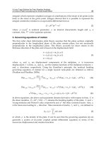
the hall environment, the layout and representative images is presented in Fig. 21.
The corridor has been prepared with a total of 3 nodes separated from each other about
22.5m. The total length of the corridor is about 52.2m with 1.74m in width. Meanwhile, in
the hall environment, 5 nodes have been arranged. Distance between each node is vary,
where the longest distance is between node 2 and node 3 which is about 4 meter as shown in
Fig. 21.
Fig. 21. Experiment layout of the hall environment with representative images of each node
8.1 Experimental setup
For the real-world experiments outlined in this research study, the ZEN360 autonomous
mobile robot was used. It is equipped with a CCD colour video camera. The robot system is
explained in section 4. Each image acquired by the system has a resolution of 320 x 240.
The robot is scheduled to navigate from Node 1 to Node 3, passing through Node 2 at the
middle of the navigation in the corridor environment. Meanwhile, in the hall environment,
the robot will have to navigate from Node 1 to Node 5 following the sequences of the node,
and is expected to perform a turning task at most of the nodes.
The robot was first brought to the environments and a recording run has been executed. The
robot is organized to capture images in order to supply environmental visual features for
both position and orientation identification. The images were captured following the
method explained in section 7.1 and 7.3, at around each specified nodes. Then, the robot
generated a topological map and the visual features were used for training NNs.
After the recording run, the robot was brought once again to the environments to perform
the autonomous run. Before start moving, the robot will identify its current position and
based on the input of target destination, it will then plan the path to move on. Path planning
Advances in Robot Navigation
50
involves determining how to get from one place (node) to another, usually in the shortest
manner possible. The work in this research study does not deal with this problem explicitly,
though the topological map produced can be used as input to any standard graph planning
algorithm.
A number of autonomous runs were conducted to see the performance of the proposed
navigation method. In the experiments conducted at the corridor, the robot navigates from
Node 1 and while moving towards Node 2, the robot corrects its own orientation at each
step of movement based on the result of a comparison between visual features of the
captured image against the 5 directions NN data of Node 2. The same procedure is used for
a movement towards Node 3 from Node 2. The robot is set to localize itself at each node
along the path during the navigation. An identical process is employed by the robot when
navigating in the hall environment, where it starts navigating from Node 1 to Node 2, and
followed by Node 3 and 4 before finished at the Node 5.
8.2 Experiment results
The result of the navigation experiments are displayed in Fig. 22 and Fig. 23. The robot
successfully moved on the expected path towards Node 3 in each run of the result in Fig. 22.
Even though at some points, especially during the first run test, the robot moved slightly
away from the expected path on the centre of the corridor (to the right and left), it still came
back to the path. The results demonstrated the proposed method to be asymptotically
dexterous as the robot displacement in x axis along the expected path during the navigation
is small.
Simultaneously, the experiments conducted at the hall environment are producing
successful results as well (Fig. 23). The robot was able to navigate along the expected path,
identified Node 2, 3 and 4 and turned safely towards the next node. Incidentally, after
navigating half of the journey between Node 2 and Node 3 in the second run, the robot
movement fell out from the path (to the left). Nevertheless, it still accomplished to move
back to the path just before recognizing Node 3. This proved that the robot is able to
determine its own moving direction and correct it towards the target.
The localized positions were very much near to the centre of the nodes except for Node 4
where the robot identified the node a bit earlier. The environmental factor surrounding
might give influence to the localization performance that caused the robot to localize the
node slightly far before reaching near the node. As the node is assigned quite near to the
door at the north side of the hall environment, and furthermore the door width is quite
large, there are possibilities that sunlight from the outside might entering the door and
affected the robot localization performance. In fact, the robot is facing directly towards the
door when navigating from Node 3 to Node 4. Although the discussed factors may give
influences to the robot localization performance, the robot is still able to turn to the right
successfully and move towards the correct path and arrived at Node 5, safely and
successfully.
As an overall conclusion, the navigation results proved that the proposed navigation
components have successfully operating properly under experimental conditions, allowing
the robot to navigate in the environments while successfully recognize its own position and
the direction towards the target destination. The robot is able to control its own posture
while navigating and moved along the expected path without losing the direction to the
target destination.
Vision-only Motion Controller for Omni-directional Mobile Robot Navigation
51
Fig. 22. Results of the navigation experiment conducted at the corridor environment
Advances in Robot Navigation
52
a) Experimental result; blue path – first run, red path – second run
D EFGH
A N ML K
B
C
J
I
A
B
C
D
E
F
G
H
I
J
K
L
M
N
b) Navigation sceneries at selected places
Fig. 23. Result of the navigation experiment conducted at the hall environment
Node 2
Node 1
Node 3
Node 4
Node 5
Vision-only Motion Controller for Omni-directional Mobile Robot Navigation
53
9. Conclusion
This chapter was concerned with the problem of vision-based mobile robot navigation. It
built upon the topological environmental representation described in section 2.1. From the
outset of this work, the goal was to build a system which could solve the navigation
problem by applying a holistic combination of vision-based localization, a topological
environmental representation and a navigation method. This approach was shown to be
successful.
In the proposed control system, NN data is prepared separately for place and orientation
recognition. By separating the NN data of place and orientation recognition, the navigation
task was superbly achieved without any effect caused by the recognition domain area. This
is mainly due to the fact that the width of the domain area for orientation recognition is
practically wide under the method of preparing the instructor data as explained in section
7.3. At the same time, the width of domain area for position recognition is small in order to
control the width and to prevent from robot stop slightly early before reaching certainly
near around the target destination (node).
Furthermore, results from several navigation experiments lead the research work to identify
a new way of preparing the instructor data for position recognition and hence improve the
efficiency of localization process during navigation. With the new preparation method, it is
believed that the domain area for localization of selected node can be control and the width
could be smaller. This condition will help to prevent for early position recognition and help
the robot to stop in somehow much more nearer to the centre of the node. Moreover,
recognizing node at nearer point, it will help the robot to avoid other problems such as
turning to early and crash to wall etc. at a node which is selected at a junction. In fact, the
new instructor data acquiring method will help to reduce burdens on the end user during
the recording run.
10. References
Asama, H.; Sato, M.; Kaetsu, H.; Ozaki, K.; Matsumoto, A. & Endo, I. (1996). Development of
an Omni-directional Mobile Robot with 3 DoF Decoupling Drive Mechanism,
Journal of the Robotics Society of Japan (in Japanese), Vol.14, No.2, pp. 249-254, 1996.
Burrascano, P.; Fiori, S.; Frattale-Mascioli, F.M.; Martinelli, G.; Panella, M.; & Rizzi, A.
(2002). Visual Path Following and Obstacle Avoidance by Artificial Neural
Networks, In "Enabling Technologies for the PRASSI Autonomous Robot" (S. Taraglio
and V. Nanni, Ed.s), ENEA Research Institute, pp. 30-39, 2002.
Geodome, T.; Tuytelaars, T.; Van Gool, L.; Vanacker, G.; & Nuttin, M. (2005).
Omnidirectional Sparse Visual Path Following with Occlusion-robust Feature
Tracking, Proceedings of the 6
th
Workshop on Omnidirectional Vision, camera Networks
and Nonclassical Cameras in conjunction with ICCV, 2005.
Kawabe, T.; Arai, T.; Maeda, Y.; & Moriya, T. (2006). Map of Colour Histograms for Robot
Navigation, Intelligent Autonomous Systems 9, pp. 165-172, 2006.
Mariottini, G.; Alunno, E.; Piazzi, J.; & Prattichizo, D. (2004). Epipole-based Visual Servoing
with Central Catadioptric Camera, Proceedings of the IEEE International Conference on
Robotics and Automation, pp. 497-503, 2005.
Advances in Robot Navigation
54
McClelland, J.L.; Rumelhart, D.E.; & the PDP Research Group (1986). Parallel Distributed
Processing: Explorations in the Microstructure of Cognition, Volume 2,
Psychological and Biological Models, MIT Press, Cambridge, Massachusetts, 1986.
Meng, M. & Kak, A.C. (1993). Mobile Robot Navigation Using Neural Networks and
Nonmetrical Environment Models, IEEE Control Systems Magazine, Vol.13, No.5, pp.
30-39, 1993.
Morales, Y.; Carballo, A.; Takeuchi, E.; Aburadani , A.; & Tsubouchi, T. (2009). Autonomous
Robot Navigation in Outdoor Pedestrian Walkways, Journal of Field Robotics, Vol.26,
No.2, pp. 609-635, 2009.
Na, Y.K. & Oh, S.Y. (2004). Hybrid Control for Autonomous Mobile Robot Navigation Using
Neural Network based Behavior Modules and Environment Classification, Journal
of Autonomous Robots, Vol.15, No.2, pp. 193-206, 2004.
Park, I. & Kender, J.R. (1995). Topological Direction-giving and Visual Navigation in Large
Environments, Journal of Artificial Intelligence, Vol.78, No.1-2, pp. 355-395, 1995.
Pomerleau, D.A. (1989). ALVINN: An Autonomous Land Vehicle in a Neural Network,
Technical Report CMU-CS-89-107, 1989.
Rizzi, A. & Cassinis, R. (2001). A Robot Self-localization System Based on Omnidirectional
Colour Images, Journal of Robotics and Autonomous Systems, Vol.34, No.1. pp. 23-38,
2001.
Rizzi, A.; Cassinis, R.; & Serana, N. (2002). Neural Networks for Autonomous Path-
following with an Omnidirectional Image Sensor, Journal of Neural Computing &
Applications, Vol.11, No.1. pp. 45-52, 2002.
Rumelhart, D.E.; McClelland, J.L.; & the PDP Research Group (1986). Parallel Distributed
Processing: Explorations in the Microstructure of Cognition, Volume 1,
Foundations, MIT Press, Cambridge, Massachusetts, 1986.
Swain, M. & Ballard, D. (1991). Colour Indexing, International Journal of Computer Vision,
Vol.7, No.1, pp. 11-32, 1991.
Ulrich, I. & Nourbakhsh, I. (2000). Appearance-based Place Recognition for Topological
Localization, Proceedings of the IEEE International Conference on Robotics and
Automation, pp. 1023-1029, 2000.
Vassallo, R.F.; Schneebeli, H.J.; & Santos-Victor, J. (1998). Visual Navigation: Combining
Visual Servoing and Appearance Based Methods, Proceedings of the 6th International
Symposium on Intelligent Robotic Systems, pp. 137-146, 1998.
0
Application of Streaming Algorithms and DFA
Learning for Approximating Solutions to
Problems in Robot Navigation
Carlos Rodríguez Lucatero
Universidad Autónoma Metropolitana Unidad Cuajimalpa
México
1. Introduction
The main subject of this chapter is the robot navigation what implies motion planning
problems. With the purpose of giving c ontext to this chapter, I will start m aking a general
overview of what is robot motion planning. For this reason, I will start giving some abstract
of the general definitions and notions that can be frequently found in many robot motion
planning books as for example (Latombe (1990)). After that I will talk about some robot
motion problems that can be found in many research articles published in the last fifteen
years and that have been the subject of some of my own research in the robot navigation field.
1.1 Robot motion planning and configuration space of a rigid body
The purpose of this section is to define the notion of configuration space when a robot is a
rigid object without c inematic and dynamic limitations. One of t he m ain goals of robotics
is to create autonomous robots that receive as input high level descriptions of t he tasks to
be performed without further human in tervention. For high level description we mean to
specify the what task moreover than the how to do a task. A robot can be defined as a flexible
mechanical device equiped with sensors and controled by a computer. Among some domains
of application of these devices it can be mentioned the following:
• Manufacturing
• Garbage recolection
• Help to inabilited people
• Space exploration
• Submarine exploration
•Surgery
The robotics field started up big challenges in Computer Science and tends to be a source of
inspiration of many new concepts in this field.
1.2 Robot motion planning
The development of technologies for autonomous robots is in strong relationship with the
achievements in computational learning, automatic reasoning systems, perception and control
3
2 Will-be-set-by-IN-TECH
research. Robotics give place to very interesting and important issues such as the motion
planning. One of the concerns of motion planning is for example, what is the sequence of
movements that have to be performed by a robot to achieve some given objects configuration.
The less that can be hoped from an autonomous robot is that it has the hability to plan his
own motions. At first sight it seems an easy job for a human because we normally do it all the
time, but it is not so easy for the robots given that it has strong space and time computational
constrains for performing it in an computational efficient way. The amount of mathematical
as well as algorithmic that are needed for the implementation of a somehow general planner
is overhelming. The first computer controlled robots appear in the 60’s. However the
biggest efforts have been lead during the 80’s. Robotics and robot motion planning has been
benefitted by the thoretical and practical knowledge produced by the re search on Artificial
Intelligence, Mathematics, Computer Science and Mechanical Engineering. As a consequence
the computational complexity implications of the problems that arise in motion planning can
be better grasped. This allow us to understand that robot motion planning is much more than
to plan the movements of a robot avoiding to collide with obstacles.
The motion planning have to take into account geometrical as well as physical and temporal
constrains of the robots. The motion planning under uncertainty need to i n teract with the
environment and use t he sensors information to take the best decision when the information
about the world is partial. The concept of configuration space was coined by (Lozano-Perez
(1986)) and is a mathematical tool for representing a robot as a point in an appropiate space.
So, the geometry as well as the friction involved on a task can be mapped such configuration
space. Many geometrical tool such as the geometrical topology and algebra are well adapted
to such a representation. An alternative tool used frequently for motion planning is the
potential fields approach. The figures 1 and 2 are an example of a motion planning simulation
of a robot represented by a rectangular rod that moves in a 2D work space and with 3D
configuration space (
(x
i
, y
i
) position in the plane,(θ
i
) orientation). This simulation uses a
combination of configuration space planner and potential method planner.
Fig. 1. Robot motion planning simulation
1.3 Path planning
A robot is a flexible mechanical device that can be a manupulator, an articulated hand, a
wheled vehicule, a legged mechanical device, a flying platform or some combination of all
the mentioned possibilities. It has a work space and then it is subject to the nature laws. It is
autonomous in the sense that it has capability to plan automatically their movements. It is
almost impossible to preview all the possible movements for performing a task. The more
complex is the robot more critcal becomes the motion planning process. The motion planning
56
Advances in Robot Navigation
Application of Streaming Algorithms and DFA Learning for Approximating Solutions to Problems in Robot Navigation 3
Fig. 2. Potential fields over a Voronoi diagram
is just one of the many aspects involved in the robot autonomy, the other could be for instance
the real time control of the movement or the sensing aspects. It is clear that the motion
planning is not a well defined problem. In fact it is a set of problems. These problems are
variations of t he robot motion planning problem whose computational complexity depend
on the s ize of the dimension of the configration space where the robot is going to work, the
presence of sensorial and/or control uncertainties and if the obstacles are fix or mobile. The
robot motion navigation problems that I have treated in my own research are the following
• Robot motion planning under uncertainty
• Robot motion tracking
• Robot localization and map building
The methods and results obtained in my research are going to be explained in the following
sections of this chapter.
2. Robot motion planning under uncertainty
As mentioned in the introduction section the robot motion planning become computionally
more complex if the dimension of the configuration space grows. In the 80’s many
computationally efficient robot motion planning methods have been implemented for
euclidean two dimensional workspace case, with plannar polygonal shaped obstacles and
a robot having three degrees of freedom (Latombe et al. (1991)). The same methods worked
quite well for the case of a 3D workspace with polyhedral obstacles and a manipulator robot
with 6 articulations or degrees of freedom. In fact in this work (Latombe et al. (1991)) they
proposed heuristically to reduce the manipulators degrees of freedom to 3 what gives a
configuration space of dimension 3. By the same times it was proved in (Canny & Reif (1987);
Schwartz & Sharir (1983)) that in the case of dealing with configuration spaces of dimension
n or when obstacles in 2-dimensional work spaces move, the robot motion planning problem
become computationally untractable (NP
− hard, NEXPTI ME, e tc.). All those results were
obtained under the hipothesis that the robot dont have to deal with sensorial uncertainties
and that the robot actions were performed without deviations. T he reality is not so nice and
when those algorithms and methods were executed on real robots, many problems arised due
to the uncertainties. The two most important sources of uncertainties were the sensors and
57
Application of Streaming Algorithms and
DFA Learning for Approximating Solutions to Problems in Robot Navigation
4 Will-be-set-by-IN-TECH
the actuators of the robot. The mobile robots are equiped with proximity sensors and cameras
for trying to perform their actions without colliding on the walls or furniture that are placed
on the offices or laboratories where the plans were to be executed. The proximity sensors
are ultrasonic sensors that present sonar reflection problems and give unaccurate information
about the presence or absence of obstacles. In figure 3 it is shown a simulation example,
running over a simulator that we have implemented some years ago, of a mobile robot using
a model of the sonar sensors. The planner used a quadtree for the division of the free space. It
can be noticed in figure 3 that the information given by the sonar sensors is somehow noisy.
Fig. 3. Planner with sonar sensor simulation
The visual sensors present calibration problems and the treatment of 3D visual information
some times can become very hard to deal with. If we take into account these uncertainties
the motion planning problem become computationally complex even for the case of
2D robotic workspaces and configurations of low dimension (2D or 3D)(Papadimitriou
(1985);Papadimitriou & Tsitsiklis (1987)). The motion planning problems that appear due to
the sensorial uncertainies attracted many researches that proposed to make some abstractions
of the sensors and use bayesian models to deal with it (Kirman et al. (1991); Dean &
Wellman (1991); Marion et al. (1994)). In (Rodríguez-Lucatero (1997)) we study the three
classic problems, evaluation, existence and optimization for the reactive motion strategies in the
frame of a robot moving with uncertainty using various sensors, based on traversing colored
graphs with a probabilistic transition model. We first show how to construct such graphs for
geometrical scenes and various sensors. We then mention some complexity results obtained
on evaluation, optimization and approximation to the optimal in the general case strategies,
and at the end we give some hints about the approximability to the optimum for the case of
reactive strategies. A planning problem can classically be seen as an optimum-path problem
in a graph representing a geometrical environment, and can be solved in polynomial t ime
as a function of the size of the graph. If we try to execute a plan π, given a starting point s
and a terminating point t on a physical device such as a mobile robot, then the probability of
success is extremely low simply because the mechanical device moves with uncertainty. If the
environment is only partially known, then the probability of success is even lower. The robot
needs to apply certain strategies to re adjust itself using its sensors: in this paper, we define
such strategies and a notion of robustness in order to compare various strategies. Concerning
the research that we have done in (Rodríguez-Lucatero (1997)), the motion planning under
uncertainty problem that interested us was the one that appears when there are deviations
in execution of the commands given to the robot. These deviations produced robot postion
uncertainties and the need to retrieve his real position by the use of landmarks in the robotic
scene. For the sake of clarity in the exposition of the main ideas about motion planning under
58
Advances in Robot Navigation
Application of Streaming Algorithms and DFA Learning for Approximating Solutions to Problems in Robot Navigation 5
uncertainty, we will define formally some of the problems mentioned. Following the seminal
work of Schwartz and Sharir (Schwartz & Sharir (1991)), we look at the problem of planning
with uncertainty, and study its computational complexity for graph-theoretical models, using
the complexity classes BPP and IP. Given a graph with uncertainty, one looks at the
complexity of a path problem in terms of the existence of a strategy of expectation greater than
S (a threshold value). Such problems have been considered in (Valiant (1979);Papadimitriou
(1985)) with slightly different probabilistic models, and the problem is #P-complete in Valiant’s
model, and PSPACE-complete in Papadimitriou’s model.
2.1 Valiant’s and Papadimitriou’s model
Let G =< V, E > be an oriented graph of domain V with E ⊆ V
2
the set of edges, and let
s, t
∈ V be given. Let p(e) be the probability that the edge e exists: p : E → [0, 1],andletS be
a numerical value, used as a threshold. The problem is to decide if the expectation to reach s
from t is greater than S.
In (Valiant (1979)) it is shown that this problem is #P-complete, i.e. can’t be solved in
polynomial time, unless some unlikely complexity conjectures were true.
This problem with uncertainty is PSPACE,althoughnotPSPACE
−complete. In
(Papadimitriou (1985)) a different probabilistic model is considered where the probability of
edge-existence is more complex. Let p : E.V
→ [0, 1]. p(e, v) is the probability that e exists,
when w e are on v.
The problem DGR or Dynamic Graph Reliability is the decision problem where given G, s, t, S, p,
we look for the existence of a strategy whose probability of success is greater than S.
DGR is PSPACE-complete, and is the prototype of problems that can be approached as games
against nature.
In (Rodríguez-Lucatero (1997)), I considered a global model of uncertainty, and defined the
notion of a robust strategy. We then give simple examples of robust and non-robust strategies,
by evaluating the probability of success. This task can be quite complex on a large scene with
unknown obstacles, and hence we wanted to study strategies that are e asy to be evaluated
and try to keep its level of performance by using sensors.
Under this colored graph model I defined the existence of one coloration and one Markovian
strategy denoted as EPU and obtained some complexity results.
2.2 The colored graph model
In our model, the free space is represented with a labeled hypergraph in which the vertices
are associated with both the robot’s state and the expected sensor’s measures in this state, a nd
the label edges indicates the recommended action for reaching a vertex from one another.
2.2.1 The coloration method
In (Kirman et al. (1991)) a model o f sensors is used to relate the theoretical model with the
physical model. It is used for the description of specific strategies, which would reduce the
uncertainty in a planning system. Our approach is interested in the comparison of different
strategies, that include the ones described in (Kirman et al. (1991)).
Rather than using strictly quantitative measures from the sensors, we model with colors some
qualitative features in the environement. It can be the detection of a more or less close wall
from US sensors, the localisation of a landmark with vision .
So we defined for a graph G
=(V, E):
• COLOR, a finite set of colors,
59
Application of Streaming Algorithms and
DFA Learning for Approximating Solutions to Problems in Robot Navigation
6 Will-be-set-by-IN-TECH
• cl r : V → COLOR, the coloration of the vertices.
In the case clr is bijective, we talk about public uncertainty : after each move, though it
is uncertain, we know the exact position of the robot. Otherwise, we talk about private
uncertainty. This distinction is essential, because the complexity of the studied problems
depends on it.
When we want to represent a real scene using our model, we first proceed in a simple cell
decomposition of the free space. For simplicity, we are choosing right now to use a grid as
accessibility graph (generally 4 or 8- connected). Then we mark those cells with the measure
(i.e. the color) expected by the sensors, eventually using sensor data fusion as described later.
2.2.1.1 Ultrasonic sensors
As the few ultrasonic sensors of our robot are not very reliable, we first choose an extremly
simple model (1 in figure 4 ) with three different colors; the only thing we expect to detect is
a local information : we can observe either NOTHING,aWALL or a CORNER.Beingmore
confident, we then introduce an orientation criterion which bring us to a model (2 in figure 4)
with nine colors;
Model 1 : 3 colors Model 2 : 9 colors
Fig. 4. Some simple models of US sensors
Many variations can be obtained by integrating some quantitative measures in qualitative
concepts, like the colors previously described with a notion of close or far. For special types of
graphs and related problems, many models have been introduced, one of them was presented
in (Dean & Wellman (1991)),
Using t he second model of coloration, we can obtain a scene such as figure 5. We first drew a
grid on which we have suppressed the vertices occupied by obstacles. We then drew the color
of the expected US measure on each vertex.
Fig. 5. A scene with two rooms and a door, using model 2 of US sensors
2.2.2 Moving with uncertainty
When executing an action, the new robot state can be different from the expected one. For this
reason we use a hypergraph: each edge determines in fact a set of possible arriving vertices,
with certain probabilities. The uncertainty is then coded by a distribution probability over the labeled
edges.
60
Advances in Robot Navigation
Application of Streaming Algorithms and DFA Learning for Approximating Solutions to Problems in Robot Navigation 7
In (Diaz-Frias (1991)) we can find a more formal definition of this model, in which two kinds of
plans are considered: fixed plans and dynamical plans or strategies. In the rest of the section,
we review the notion of robust strategy and we discuss the probability of robustness.
On a graph G
=(V, E),wedefine:
• LABEL, a finite set of basic command on G;
on a 4-connected graph, for instance, w e can have :
LABEL
= {STOP, EAST, NORT H, WEST,
SOUTH
},
• lbl : V
× LABEL → V ∨{FAIL};
we then define the uncertainty on the moves by :
• δ : V
× LABEL × V → [0, 1]; δ(v
i
, l,v
j
) is the probability beeing in v
i
∈ V, executing the
command l
∈ LABEL, to arrive in v
j
∈ V. We assume δ is really a probability function, i.e.
:
∀v
i
∈ V, ∀l ∈ LABEL,
∑
v
j
∈V
δ(v
i
, l, v
j
)=1
2/3
1/6
1/6
0
1
23
4
5
6
7
8
Fig. 6. An instance of the δ function : δ(0, EAST,1)=
2
3
, δ(0, EAST,2)=δ(0, EAST,8)=
1
6
on an 8-connected grid.
2.2.3 Strategies
2.2.3.1 General case :
In the general case the strategies use his whole history f or taking a decision. For more
information see (Marion et al. (1994)) . We define the history, which is a record of all the
actions and measures : h
∈ H ⊂ (COLOR × LABEL)
∗
. The history is first initialized with
cl r
(s) ; and then, during a realization, at the step t, the color of the current vertex is the l ast
element of the history.
Definition 1. A strategy with history, or H-strategy, is a function σ
H
: H → LABEL.
2.2.3.2 Strategies without memory :
We then define two basic cases of strategies which are of interest because of their properties
in the case of public uncertainty, and also because they are easy to evaluate.
Definition 2. A Markov-strategy, or M-strategy, is a function σ
M
:
σ
M
: COLOR → LABEL
A Markov-strategy is a time-independent strategy. It depends only on the color of the current
vertex. In the case of public uncertainty, it is a function of the current vertex.
61
Application of Streaming Algorithms and
DFA Learning for Approximating Solutions to Problems in Robot Navigation
8 Will-be-set-by-IN-TECH
Definition 3. A T-strategy is a function σ
T
:
σ
T
: COLOR × N → LABEL
A T-strategy is a time-dependent strategy; It depends only of the color of the current vertex, and
the number of steps. remark : Anotionofplan is often defined. It is a particular kind of
T-strategy which depend only of the time : σ
P
: N → LABEL
For more details about other types of strategies more embeded that use a bounded memory
see (Marion et al. (1994)).
2.2.3.3 Strategies using history :
If the two different strategies described above are efficient in some cases (as we will see in a
further section, see section 4.2), other strategies using history can be more efficient. That is
why we define a new kind of strategy named D-strategy.
For a graph G
=(V, E), a model of uncertainty δ, and a strategy σ,let’sdefineatstepk :
• s
k
∈ V the position and h
k
the history ; s
k+1
is a function of G, δ, σ, h
k
, s
k
,andh
k+1
=
h
k
∪ (co l(s
k+1
), σ(h
k
)).
•
∀v ∈ V, f
h
k
(v)=Pr(s
k
= v | h
k
), the probability of being in v at the step t, knowing the
history.
At the step k
+ 1, f
h
k+1
(v) is defined by :
[ξ
h
k+1
(v)=
∑
u∈V
f
h
k
(u)δ(u, σ(h
k
), v) if co l(v)=co l(s
k+1
)
0otherwise
][f
h
k+1
(v)=
ξ
h
k
+1
(v)
∑
u∈V
ξ
h
k
+1
(u)
]
Let be Φ : H → [0, 1]
|V|
, the function which associate for all h, Φ(h)= f
h
the distribution over
the vertices. We note
F = Φ(H).
Definition 4. A D-strategy is a function : σ :
F×N → LABEL
A D-strategy only depends on the time and the distribution over the vertices.
2.2.4 Criteria of evaluation of a strategy
2.2.4.1 Reliability :
We are first interested in reaching t from s with the maximal possible probability, but in a
limited time k :
R
(σ, k)=Prob (s
σ
→ t ||h|≤ k)
We note, at the limit:
R
(σ)=R(σ, ∞)= lim
k→∞
R(σ, k)
This criterion is essentially uses for M-strategy, for which we have means to compute this
value (see section 3.1).
Definition 5. Astrategyσ
opt
is R-k-optimal iff :
∀σ : R(σ, k) ≤ R(σ
opt
, k)
Definition 6. Astrategyσ
opt
is R-optimal iff :
∀σ : R(σ) ≤ R(σ
opt
)
62
Advances in Robot Navigation
Application of Streaming Algorithms and DFA Learning for Approximating Solutions to Problems in Robot Navigation 9
2.3 Definition of the problems
Given G =(V, E), an uncertainty function δ, a coloration function clr, a command function
lbl,twopointss, t
∈ G (resp. source and target), and a criterion C, l et us consider the following
problem :
• PU, the decision problem
Output : 1, if there exists a strategy which satisfies the criterion, else 0.
• PU
opt
, the optimization problem
Output : the optimal strategy for the criterion.
And for a given strategy σ :
• PU
σ
, the evaluation problem
Output :thevalue
C(σ).
3. M-strategies vs.T-strategies
3.1 The public uncertainty case
In that case T-strategy and M-strategy are interesting :
Theorem 1. A T-strategy R-optimal for a given k does exist and can be constructed in time polynomial
in k and the size of the input graph with uncertain moves.
Theorem 2. For every graph with uncertain moves and a source/target pair of vertices there exists an
R-optimal M-strategy.
Note that the first theorem consider finite time criterion, and the second one infinite time
criterion. (The demonstration of these theorems and the methods to construct those optimal
strategies can be found in (Burago et al. (1993)).
Using these criteria we can compare different types of strategies under an unified frame. In
(Marion e t al. (1994)) we can find un exemple of graph where for a given number o f steps
a T-strategy works better than an M-strategy. In this same paper we showed that we can
construct more involved strategies that can be more performants but harder to evaluate, so we
proposed the simulation as a tool for estimating the performances of this kind of strategies.
3.2 Example: Peg-in-hole
We assume that we have a robot manipulator with a tactil sensor in the en d effector. This
sensor allows us to move compliantly over a planar surface. We suppose too that we have a
workspace limited by a rectangular frame, so we can detect with the fingers of the end effector
if we are touching the frame or an obstacle, by interpretation of the efforts in the fingers of the
end effector. The robotic scene is as follows:
Fig. 7. A scene for the Peg-in-hole
If we use a sensorial m odel of the tactil sensor in a similar way as we used for the ultrasonic
sensors we can obtain a colored graph representation like the next figure:
63
Application of Streaming Algorithms and
DFA Learning for Approximating Solutions to Problems in Robot Navigation
10 Will-be-set-by-IN-TECH
t
s
12
3
45
6
7
5
4
3
2
1
Fig. 8. Associated c olored graph the arrows represents the M-strategy actions
If we evaluate this M-stretegy for a number of steps k
= 7 w e obtain: R(σ
M
,20)=0.16627 as
we can see this strategy is not performant even allowing a big number of steps. We can remark
too that the coloration is not bijective so we can’t distinguish between the limiting right frame
and the right face of the r ectangular obstacle. So we can propose a T-strategy (a little variation
of the M-strategy) that for this color if k
≥ 5 we execute the action E instead of making N The
reliability for this new strategy is R
(σ
T
,20)=0.8173582 that makes a very big difference. In
the case of finite polynomial time, there may not be an optimal M-strategy as shown on figure
9. In this example, the uncertainty is public. The command are RIGHT, LEFT and STRAIGHT,
on the directed edges. The goal is to reach t from s in less than 6 steps. The moves are certain
except for some edges :
• δ
(s, RIGHT,4)=δ(s, RIGHT,1)=δ(s, LEFT,4)=δ(s, LE FT,1)=
1
2
,
• δ
(8, LE FT,t)=δ(8, LEF T, trap)=
1
2
,
An optimal strategy first choose RIGHT to arrive at 4 in one step; but in case it fails, it will
arrive there in four steps. An optimal M-strategy σ
M
will always choose on vertex 4 :
• either LEFT, taking t he risk not to arrive before the time is gone (6 steps maximum),
• either RIGHT, taking the risk to fall in the trap.
The optimal T-strategy σ
T
will choose on vertex 4 :
• LEFT a (the safe way) if it a rrive there in only one step,
• otherwise RIGHT (a more risky path).
Thus the probability of success of those two strategies are :
[R(σ
M
,6)=
1
2
≤ R(σ
T
,6)=
3
4
]
s
t
trap
1
2
3
4
5
67
8
Certain move
uncertain move
Fig. 9. σ
T
is optimal though σ
M
is not.
64
Advances in Robot Navigation
Application of Streaming Algorithms and DFA Learning for Approximating Solutions to Problems in Robot Navigation 11
3.3 The private uncertainty case
In the case of total uncertainty (i.e. all the v ertices have the same color),
Theorem 3. It is NP
− hard to decide if there exists a strategy which succeeds with probability 1.
Another result that we consider interesting concerns the approximability of this problem in
the case of total uncertainty, that we can state as:
Theorem 4. It is NP
− hard to decide if there exists an approximate solution.
4. Complexity of the evalution problem
4.1 Evaluation in the general case
The computation of R(σ, k) for some strategy σ maybeveryhard. Thiscanbeshownbya
reduction of 3SAT to the evaluation problem. We represent F as a table. Let be:
F
=
1≤i≤m
1≤j≤3
z
i,j
aformulawherez
i,j
are literals of the set
{x
1
, ,x
n
, x
1
, ,x
n
})
. His tabular representation is
z
1,1
z
2,1
z
m,1
z
1,2
z
2,2
z
m,2
z
1,3
z
2,3
z
m,3
where the height is 3 and the length is m (the i-th column corresponds to the i-th clause in the
formula). We say that two literals z
1
et z
2
are opposed iff z
1
⇔ z
2
. We assume that there is
not c ontradictory literals in a column. One path in F is an horizontal path P in the table build
taking one literal by column (clause), we mean that P is a list of literals as
(z
1,j
1
, z
2,j
2
, ,z
m,j
m
),
1
≤ j
i
≤ 3, 1 ≤ i ≤ m. We interpret this paths as truth value assignments. In the case that
a path have no pair of contradictory literals we say that is a model of the logic formula. The
paths without contradictions are named as opened otherwise closed.
In this way we can construct a graph as:
t
s
z11
z12
z13
z21
z22
z23
zm1
zm2
zm3
. . .
. . .
. . .
Fig. 10. Example multilayer graph for the reduction of 3SAT to PU
The triplets of vertex in the vertical sense represents the columns of the table. The dashed
lines are probabilistic transitions of the strategy σ, that is, when the strategy takes a dashed
line he arrives to one of the vertex in the next layer with a probability of 1 /3 it doesn’t matter
what edge has been taken.
In the case of continue lines, they are safe lines, that is if the strategy takes it, she follows it
certainly. The strategy selects the edge seeing the walked path (i.e. a prefix of a path in F). If
at this moment the path is an opened one the strategy takes a dashed line (i.e. makes a random
mouvement), otherwise it takes a safe line going through the trap. If the strategy arrives to the
65
Application of Streaming Algorithms and
DFA Learning for Approximating Solutions to Problems in Robot Navigation
12 Will-be-set-by-IN-TECH
last layer by an opened path, then it transits to the goal by a safe line. We conclude that if F
satisfaied then R
(σ, k) > 0.
Before this result, the evaluation problem is a hard one in the general case. Even that we can
try t o work w ith strategies that are easy to evaluate as the M-strategies and T-strategies.
4.2 Evaluation of M-strategy & T-strategy
Theorem 5. Computing R(σ, k) if σ is a M-strategy, or a T-strategy which stops in polynomial time
k , can be done in polynomial time (idem E
(σ, k) ).
proof :
It follows from Markov chain theory : Let us note μ
k
the distribution over the vertices at step k.
μ
0
( s)=1.
AM-strategyσ
M
can be seen as a transition matrix M =[m
ij
]. If the decision of the M-strategy in i is l(i):
from i,movetoj.
m
ik
=
1ifk
= j,
0 otherwise
We compute P
=[p
ij
] with : p
ij
= δ(i, l(i), j) Then, ∀i ∈ N : μ
i+1
= Pμ
i
and R(σ
M
, k)=μ
k
.
We can do the same thing with a T-strategy σ
T
, except that in this case, the decision depends also of the
time : l
( i, t). Then we define P(t ) in the same way, and :
∀i ∈ N : μ
i+1
= P(i)μ
i
and R(σ
T
, k)=μ
k
.
Theorem 6. The problems of evaluating a M-strategy for a infinite time criterion can be solved in
polynomial time.
proof :
An other result from Markov chain theory : we just compute the stationary distribution over the
vertices π (ie. solve Pπ
= π).
4.3 Definition of EPU and complexity
One other approach for trying to deal with this problem is to explore the posibility of working
with strategies that are easy to evaluate (M-strategies) and use some fixed amount of colours
for keeping his performance. In this section we deal with this problem and give some
complexity results about that.
Definition 7. Problem KNAPSACK: to find a subset of a set where each element is affected by two
values, one given by a size function s and the other given by a weight function v. T he addition of all
the sizes in this sub-set must be lesser than a given value and the addition of the weights bigger than
another given value.
INPUT: U
= {u
1
, ,u
n
} a function s : u ∈ U → Z
+
a function v : u ∈ U → Z
+
two integers B
et K
OUTPUT: 1if
∃U
⊂ U, such that
∑
u
∈U
s(u
) ≤ Band
∑
u
∈U
v(u
) ≥ K, and 0 otherwise.
Definition 8. EPU: problem of the existence of one coloration and one M-strategy given a fixed number
of colors a nd a threshold.
INPUT: G
(V, E), s, t ∈ V, k, q ∈ Q, T, μ
OUTPUT: 1if
∃clr : v ∈ V →{1, ,k} : ∃σ
M
such that R(σ
M
, T) ≥ q,and0 otherwise.
Theorem 7. EPU is NP-complet
66
Advances in Robot Navigation
Application of Streaming Algorithms and DFA Learning for Approximating Solutions to Problems in Robot Navigation 13
proof : We show it by a reduction of KNAPSACK to EPU.ItbelongstoNP because if we want to
obtain a M-strategy with T steps, given k colours and a threshold, we colour the graph randomly an
associate an action to each color. Based on this, we calculate a Markov matrix an we evaluate the strategy
in polynomial time. In this way we prouve that EPU
∈ NP.
The goal is to find a polynomial transformation of KNAPSACK to EPU. For this end we build 2 graphs
having n
+ 2 v ertices as we show in the figure 11.
t
s
d
e
f
a
b
c
Fig. 11. Example of the graph for knapsack to EPU
We associate each graph to each restriction of KNAPSACK.
As it can be verified in the figure 11 we defined a graph that has one layer that contains n vertices that we
name selection points.
This layer associates each selection vertex to an element of the KNAPSACK set U. We have two additional
vertices s for the starting point and t for the goal. We draw n edges between s and each element of the
selection layer, and we assign a uniform probability 1/n to each one.
Similarly we define an edge going from each element of the selection layer to the goal vertex t.Thenwe
fix the number of steps T
= 2, one for going from s to the selection layer an the other one for going from
the selection layer to the goal vertex t
We fix the nomber of available colors k to 2 because we want to interpret the selection of elements in U as
an assignement of colors and associate to each color one action. Next we define a probabilistic deviation
model in function of the associated weights of elements for the second restriction of KNAPSACK as
follows:
∀1 ≤ i ≤ B (u(i), t) ∈ Eμ
1
( u, σ
M
( cl r(u(i))),t)=
p
1
=
u(i)
V
1 − p
1
trap
As we can see we introduced a parameter V that represents the total weight of the set U.Thisgiveus
probability values between 0 and 1.
In the same way we define for the first restriction of KNAPSACK a probabilistic deviation model in
function of the sizes associated to each element of the U as follows:
∀1 ≤ i ≤ B (u(i), t) ∈ E μ
2
( u, σ
M
( cl r(u(i))),t)=
p
2
=
s(i)
S
trap
1
− p
2
As we can see we introduced a parameter S that represents the total size of the set U.Thisgiveus
probability values between 0 and 1.
We have 2 label actions : one for move to t and the other for stop. Next we relate the color selected and
the action move to t and the color not selected with the action stop.
For finishing the transformation we relate the thresholds q
1
et q
2
for each graph with the parameters of
the KNAPSACK as follows:
q
1
=
K
n × V
and
67
Application of Streaming Algorithms and
DFA Learning for Approximating Solutions to Problems in Robot Navigation
14 Will-be-set-by-IN-TECH
q
2
= 1 −
B
n × S
Remark : In the definition of the distribution μ
1
we talked about a p robability to get traped equal to
1
− p, and a probability p to have succes in the mouvement. So we cant arrive to the goal since a vertex
coloured with non selected. The same is valid for μ
2
too.
Before that we have for the first graph:
R
1
( σ
M
, T)=
∑
π∈PAT H S
Prob(π réalisation de σ
M
)=
T
∑
i=0
n
∑
j=1
μ
1
( i, σ
M
, j)
and for the second one:
R
2
( σ
M
, T)=
∑
π∈PAT H S
Prob(π réalisation de σ
M
)=
T
∑
i=0
n
∑
j=1
μ
2
( i, σ
M
, j)
So we can proclaim that it exists a subset for the KNAPSACK iff it exists a colouring clr and an associated
strategy σ
M
that fullfils the performance q
1
for the first graph an simultaneously q
2
for the second one.
That is that we have shown that KNAPSACK
⇒ EPU.
For showing the reduction in the oposite sense we say that if we have one colouring and an M
−strategy
associated that fullfils the performace q
1
and q
2
en each graph then it exist a subset U‘ ⊂ U for
KNAPSACK. For this we only need to label vertex of the selection layer with one element of the U and
take the vertices that have a selected color. This gives a subset that works for KNAPSACK. In this way
we prouved that KNAPSACK
⇐ EPU and we can proclaim that:
KNAPSACK
⇔ EPU
This result show that EPU is a hard one but what is intresting is that KNAPSACK is one of
the rare problems that are NP-complet and at the same time arbitrarly a pproximable. That is
that KNAPSACK has a fully polynomial approximation schema (FPTAS). So if we can make
a special k ind of transformation from EPU to KNAPSACK called L
− reduction (for details
see (Papadimitriou & Yannak akis (1991)) and (Papadimitriou & Steiglitz (1982))), we can find
good approximations to the optimal for the EPU optimazing problem.
5. Robot motion tracking, DFA learning, sketching and streaming
Another robot navigation problem that has attracted my attention in the last six years has
been the robot tracking problem. In this problem we are going to deal with another kind
of uncertainty. The uncertainty on the setting of two robots that, one that plays de rôle of
observer and the other that of target. This problem has to do with other kind o f uncertainty
that appears in robot navigation problems. The uncertainty on the knowledge o f the other
reactions i n a given situation. This situation arise when there are two or more robots or
agents in general that have to perform their tasks in the same time and to share the working
space. Many everyday life situations can be seen as an interaction among agents, as can
be to play football , to drive a car in Mexico city streets, or to play chess with your wife.
The robot tracking is not the exception. In the examples given above as well as in the robot
tracking case, the agents observe the actions taken by the other agents, and try to predict the
behaviour of them a nd react in the best possible way. The fundamental difference between
the examples that we have given and the robot tracking problem is that the agents in the
last case are robots and as consequence they are limited in computational power. Because of
68
Advances in Robot Navigation