david roylance mechanics of materials Part 10 ppt
Bạn đang xem bản rút gọn của tài liệu. Xem và tải ngay bản đầy đủ của tài liệu tại đây (447.31 KB, 25 trang )
1 Tx -2000
1Ty 0
1Tz 0
2Tz 0
3Tz 0
4 Tx 2000
4 Ty 1000
4Tz 0
5Tz 0
Material Usage Summary
Material: steel
Number: 6
Length: 682.8427
Mass: 0.0000
Total mass: 0.0000
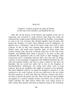
The vertical displacement of node 3 (the DOF 2 value) is -0.0844, the same value obtained by the
closed-form methods of Module 5. Figure 6 shows the velvet graphical output for the truss deflections
(greatly magnified).
Figure 6: The 6-element truss in its original and deformed shape.
General Stress Analysis
The element stiffness matrix could be formed exactly for truss elements, but this is not the case
for general stress analysis situations. The relation between nodal forces and displacements are
not known in advance for general two- or three-dimensional stress analysis problems, and an
approximate relation must be used in order to write out an element stiffness matrix.
In the usual “displacement formulation” of the finite element method, the governing equa-
tions are combined so as to have only displacements appearing as unknowns; this can be done by
using the Hookean constitutive equations to replace the stresses in the equilibrium equations by
the strains, and then using the kinematic equations to replace the strains by the displacements.
This gives
L
T
σ = L
T
D = L
T
DLu = 0 (3)
9
Of course, it is often impossible to solve these equations in closed form for the irregular bound-
ary conditions encountered in practical problems. However, the equations are amenable to
discretization and solution by numerical techniques such as finite differences or finite elements.
Finite element methods are one of several approximate numerical techniques available for
the solution of engineering boundary value problems. Problems in the mechanics of materials
often lead to equations of this type, and finite element methods have a number of advantages
in handling them. The method is particularly well suited to problems with irregular geometries
and boundary conditions, and it can be implemented in general computer codes that can be
used for many different problems.
To obtain a numerical solution for the stress analysis problem, let us postulate a function
˜
u(x, y) as an approximation to u:
˜
u(x, y) ≈ u(x, y)(4)
Many different forms might be adopted for the approximation
˜
u. The finite element method
discretizes the solution domain into an assemblage of subregions, or “elements,” each of which has
its own approximating functions. Specifically, the approximation for the displacement
˜
u(x, y)
within an element is written as a combination of the (as yet unknown) displacements at the
nodes belonging to that element:
˜
u(x, y)=N
j
(x, y)u
j
(5)
Here the index j ranges over the element’s nodes, u
j
are the nodal displacements, and the N
j
are
“interpolation functions.” These interpolation functions are usually simple polynomials (gen-
erally linear, quadratic, or occasionally cubic polynomials) that are chosen to become unity at
node j and zero at the other element nodes. The interpolation functions can be evaluated at any
position within the element by means of standard subroutines, so the approximate displacement
at any position within the element can be obtained in terms of the nodal displacements directly
from Eqn. 5.
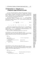
Figure 7: Interpolation in one dimension.
The interpolation concept can be illustrated by asking how we might guess the value of a
function u(x) at an arbitrary point x located between two nodes at x =0andx= 1, assuming
we know somehow the nodal values u(0) and u(1). We might assume that as a reasonable
approximation u(x) simply varies linearly between these two values as shown in Fig. 7, and
write
u(x) ≈ ˜u(x)=u
0
(1 − x)+u
1
(x)
or
10
˜u(x)=u
0
N
0
(x)+u
1
N
1
(x),
N
0
(x)=(1−x)
N
1
(x)=x
Here the N
0
and N
1
are the linear interpolation functions for this one-dimensional approxima-
tion. Finite element codes have subroutines that extend this interpolation concept to two and
three dimensions.
Approximations for the strain and stress follow directly from the displacements:
˜
= L
˜
u = LN
j
u
j
≡ B
j
u
j
(6)
˜
σ = D
˜
= DB
j
u
j
(7)
where B
j
(x, y)=LN
j
(x, y) is an array of derivatives of the interpolation functions:
B
j
=
N
j,x
0
0 N
j,y
N
j,y
N
j,x
(8)
A “virtual work” argument can now be invoked to relate the nodal displacement u
j
appearing
at node j to the forces applied externally at node i: if a small, or “virtual,” displacement δu
i
is
superimposed on node i, the increase in strain energy δU within an element connected to that
node is given by:
δU =
V
δ
T
σ dV (9)
where V is the volume of the element. Using the approximate strain obtained from the inter-
polated displacements, δ
˜
= B
i
δu
i
is the approximate virtual increase in strain induced by the
virtual nodal displacement. Using Eqn. 7 and the matrix identity (AB)
T
= B
T
A
T
, we have:
δU = δu
T
i
V
B
T
i
DB
j
dV u
j
(10)
(The nodal displacements δu
T
i
and u
j
are not functions of x and y, and so can be brought from
inside the integral.) The increase in strain energy δU must equal the work done by the nodal
forces; this is:
δW = δu
T
i
f
i
(11)
Equating Eqns. 10 and 11 and canceling the common factor δu
T
i
,wehave:
V
B
T
i
DB
j
dV
u
j
= f
i
(12)
This is of the desired form k
ij
u
j
= f
i
,wherek
ij
=
V
B
T
i
DB
j
dV is the element stiffness.
Finally, the integral in Eqn. 12 must be replaced by a numerical equivalent acceptable to the
computer. Gauss-Legendre numerical integration is commonly used in finite element codes for
this purpose, since that technique provides a high ratio of accuracy to computing effort. Stated
briefly, the integration consists of evaluating the integrand at optimally selected integration
points within the element, and forming a weighted summation of the integrand values at these
points. In the case of integration over two-dimensional element areas, this can be written:
11
A
f(x, y) dA ≈
l
f(x
l
,y
l
)w
l
(13)
The location of the sampling points x
l
,y
l
and the associated weights w
l
are provided by
standard subroutines. In most modern codes, these routines map the element into a convenient
shape, determine the integration points and weights in the transformed coordinate frame, and
then map the results back to the original frame. The functions N
j
used earlier for interpolation
can be used for the mapping as well, achieving a significant economy in coding. This yields what
are known as “numerically integrated isoparametric elements,” and these are a mainstay of the
finite element industry.
Equation 12, with the integral replaced by numerical integrations of the form in Eqn. 13, is
the finite element counterpart of Eqn. 3, the differential governing equation. The computer will
carry out the analysis by looping over each element, and within each element looping over the
individual integration points. At each integration point the components of the element stiffness
matrix k
ij
are computed according to Eqn. 12, and added into the appropriate positions of the
K
ij
global stiffness matrix as was done in the assembly step of matrix truss method described in
the previous section. It can be appreciated that a good deal of computation is involved just in
forming the terms of the stiffness matrix, and that the finite element method could never have
been developed without convenient and inexpensive access to a computer.
Stresses around a circular hole
We have considered the problem of a uniaxially loaded plate containing a circular hole in previous
modules, including the theoretical Kirsch solution (Module 16) and experimental determinations
using both photoelastic and moire methods (Module 17). This problem is of practical importance
—- for instance, we have noted the dangerous stress concentration that appears near rivet holes
— and it is also quite demanding in both theoretical and numerical analyses. Since the stresses
rise sharply near the hole, a finite element grid must be refined there in order to produce
acceptable results.
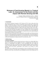
Figure 8: Mesh for circular-hole problem.
Figure 8 shows a mesh of three-noded triangular elements developed by the felt-velvet
12
graphical FEA package that can be used to approximate the displacements and stresses around
a uniaxially loaded plate containing a circular hole. Since both theoretical and experimental
results for this stress field are available as mentioned above, the circular-hole problem is a good
one for becoming familiar with code operation.
The user should take advantage of symmetry to reduce problem size whenever possible, and
in this case only one quadrant of the problem need be meshed. The center of the hole is kept
fixed, so the symmetry requires that nodes along the left edge be allowed to move vertically
but not horizontally. Similarly, nodes along the lower edge are constrained vertically but left
free to move horizontally. Loads are applied to the nodes along the upper edge, with each load
being the resultant of the far-field stress acting along half of the element boundaries between
the given node and its neighbors. (The far-field stress is taken as unity.) Portions of the felt
input dataset for this problem are:
problem description
nodes=76 elements=116
nodes
1 x=1 y=-0 z=0 constraint=slide_x
2 x=1.19644 y=-0 z=0
3 x=0.984562 y=0.167939 z=0 constraint=free
4 x=0.940634 y=0.335841 z=0
5 x=1.07888 y=0.235833 z=0
.
.
.
72 x=3.99602 y=3.01892 z=0
73 x=3.99602 y=3.51942 z=0
74 x=3.33267 y=4 z=0
75 x=3.57706 y=3.65664 z=0
76 x=4 y=4 z=0
CSTPlaneStress elements
1 nodes=[13,12,23] material=steel
2 nodes=[67,58,55]
6 nodes=[50,41,40]
.
.
.
7 nodes=[68,67,69] load=load_case_1
8 nodes=[68,58,67]
9 nodes=[57,58,68] load=load_case_1
10 nodes=[57,51,58]
11 nodes=[52,51,57] load=load_case_1
12 nodes=[37,39,52] load=load_case_1
13 nodes=[39,51,52]
.
.
.
116 nodes=[2,3,1]
material properties
steel E=2.05e+11 nu=0.33 t=1
distributed loads
load_case_1 color=red direction=GlobalY values=(1,1) (3,1)
13
constraints
free Tx=u Ty=u Tz=u Rx=u Ry=u Rz=u
slide_x color=red Tx=u Ty=c Tz=c Rx=u Ry=u Rz=u
slide_y color=red Tx=c Ty=u Tz=c Rx=u Ry=u Rz=u
end
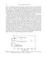
The y-displacements and vertical stresses σ
y
are contoured in Fig. 9(a) and (b) respectively;
these should be compared with the photoelastic and moire analyses given in Module 17, Figs. 8
and 10(a). The stress at the integration point closest to the x-axis at the hole is computed
to be σ
y,max
=3.26, 9% larger than the theoretical value of 3.00. In drawing the contours of
Fig. 9b, the postprocessor extrapolated the stresses to the nodes by fitting a least-squares plane
through the stresses at all four integration points within the element. This produces an even
higher value for the stress concentration factor, 3.593. The user must be aware that graphical
postprocessors smooth results that are themselves only approximations, so numerical inaccuracy
is a real possibility. Refining the mesh, especially near the region of highest stress gradient at
the hole meridian, would reduce this error.
Figure 9: Vertical displacements (a) and stresses (b) as computed for the mesh of Fig. 8.
Problems
1. (a) – (h) Use FEA to determine the force in each element of the trusses drawn below.
2. (a) – (c) Write out the global stiffness matrices for the trusses listed below, and solve
for the unknown forces and displacements. For each element assume E = 30 Mpsi and
A =0.1in
2
.
3. Obtain a plane-stress finite element solution for a cantilevered beam with a single load at
the free end. Use arbitrarily chosen (but reasonable) dimensions and material properties.
Plot the stresses σ
x
and τ
xy
as functions of y at an arbitrary station along the span; also
plot the stresses given by the elementary theory of beam bending (c.f. Module 13) and
assess the magnitude of the numerical error.
4. Repeat the previous problem, but with a symmetrically-loaded beam in three-point bend-
ing.
14
Prob. 1
Prob. 2
5. Use axisymmetric elements to obtain a finite element solution for the radial stress in a
thick-walled pressure vessel (using arbitrary geometry and material parameters). Compare
the results with the theoretical solution (c.f. Prob. 2 in Module 16).
15
Prob. 3
Prob. 4
16
ENGINEERING VISCOELASTICITY
David Roylance
Department of Materials Science and Engineering
Massachusetts Institute of Technology
Cambridge, MA 02139
October 24, 2001
1 Introduction
This document is intended to outline an important aspect of the mechanical response of polymers
and polymer-matrix composites: the field of linear viscoelasticity. The topics included here are
aimed at providing an instructional introduction to this large and elegant subject, and should
not be taken as a thorough or comprehensive treatment. The references appearing either as
footnotes to the text or listed separately at the end of the notes should be consulted for more
thorough coverage.
Viscoelastic response is often used as a probe in polymer science, since it is sensitive to
the material’s chemistry and microstructure. The concepts and techniques presented here are
important for this purpose, but the principal objective of this document is to demonstrate how
linear viscoelasticity can be incorporated into the general theory of mechanics of materials, so
that structures containing viscoelastic components can be designed and analyzed.
While not all polymers are viscoelastic to any important practical extent, and even fewer
are linearly viscoelastic
1
, this theory provides a usable engineering approximation for many
applications in polymer and composites engineering. Even in instances requiring more elaborate
treatments, the linear viscoelastic theory is a useful starting point.
2 Molecular Mechanisms
When subjected to an applied stress, polymers may deform by either or both of two fundamen-
tally different atomistic mechanisms. The lengths and angles of the chemical bonds connecting
the atoms may distort, moving the atoms to new positions of greater internal energy. This is a
small motion and occurs very quickly, requiring only ≈ 10
−12
seconds.
If the polymer has sufficient molecular mobility, larger-scale rearrangements of the atoms
may also be possible. For instance, the relatively facile rotation around backbone carbon-
carbon single bonds can produce large changes in the conformation of the molecule. Depending
on the mobility, a polymer molecule can extend itself in the direction of the applied stress, which
decreases its conformational entropy (the molecule is less “disordered”). Elastomers — rubber
— respond almost wholly by this entropic mechanism, with little distortion of their covalent
bonds or change in their internal energy.
1
For an overview of nonlinear viscoelastic theory, see for instance W.N. Findley et al., Creep and Relaxation
of Nonlinear Viscoelastic Materials, Dover Publications, New York, 1989.
1
The combined first and second laws of thermodynamics state how an increment of mechanical
work fdxdone on the system can produce an increase in the internal energy dU or a decrease
in the entropy dS:
fdx= dU − TdS (1)
Clearly, the relative importance of the entropic contribution increases with temperature T ,and
this provides a convenient means of determining experimentally whether the material’s stiffness
in energetic or entropic in origin. The retractive force needed to hold a rubber band at fixed
elongation will increase with increasing temperature, as the increased thermal agitation will
make the internal structure more vigorous in its natural attempts to restore randomness. But
the retractive force in a stretched steel specimen — which shows little entropic elasticity — will
decrease with temperature, as thermal expansion will act to relieve the internal stress.
In contrast to the instantaneous nature of the energetically controlled elasticity, the con-
formational or entropic changes are processes whose rates are sensitive to the local molecular
mobility. This mobility is influenced by a variety of physical and chemical factors, such as molec-
ular architecture, temperature, or the presence of absorbed fluids which may swell the polymer.
Often, a simple mental picture of “free volume” — roughly, the space available for molecular
segments to act cooperatively so as to carry out the motion or reaction in question — is useful
in intuiting these rates.
These rates of conformational change can often be described with reasonable accuracy by
Arrhenius-type expressions of the form
rate ∝ exp
−E
†
RT
(2)
where E
†
is an apparent activation energy of the process and R =8.314J/mol −
◦
KistheGas
Constant. At temperatures much above the “glass transition temperature,” labeled T
g
in Fig.
1, the rates are so fast as to be essentially instantaneous, and the polymer acts in a rubbery
manner in which it exhibits large, instantaneous, and fully reversible strains in response to an
applied stress.
Figure 1: Temperature dependence of rate.
Conversely, at temperatures much less than T
g
, the rates are so slow as to be negligible.
Here the chain uncoiling process is essentially “frozen out,” so the polymer is able to respond
only by bond stretching. It now responds in a “glassy” manner, responding instantaneously
2
and reversibly but being incapable of being strained beyond a few percent before fracturing in
a brittle manner.
In the range near T
g
, the material is midway between the glassy and rubbery regimes.
Its response is a combination of viscous fluidity and elastic solidity, and this region is termed
“leathery,” or, more technically, “viscoelastic”. The value of T
g
is an important descriptor of
polymer thermomechanical response, and is a fundamental measure of the material’s propensity
for mobility. Factors that enhance mobility, such as absorbed diluents, expansive stress states,
and lack of bulky molecular groups, all tend to produce lower values of T
g
. The transparent
polyvinyl butyral film used in automobile windshield laminates is an example of a material that
is used in the viscoelastic regime, as viscoelastic response can be a source of substantial energy
dissipation during impact.
At temperatures well below T
g
, when entropic motions are frozen and only elastic bond de-
formations are possible, polymers exhibit a relatively high modulus, called the “glassy modulus”
E
g
, which is on the order of 3 GPa (400 kpsi). As the temperature is increased through T
g
,the
stiffness drops dramatically, by perhaps two orders of magnitude, to a value called the “rubbery
modulus” E
r
. In elastomers that have been permanently crosslinked by sulphur vulcanization
or other means, the value of E
r
is determined primarily by the crosslink density; the kinetic
theory of rubber elasticity gives the relation as
σ = NRT
λ −
1
λ
2
(3)
where σ is the stress, N is the crosslink density (mol/m
3
), and λ = L/L
0
is the extension
ratio. Differentiation of this expression gives the slope of the stress-strain curve at the origin as
E
r
=3NRT.
If the material is not crosslinked, the stiffness exhibits a short plateau due to the ability
of molecular entanglements to act as network junctions; at still higher temperatures the entan-
glements slip and the material becomes a viscous liquid. Neither the glassy nor the rubbery
modulus depends strongly on time, but in the vicinity of the transition near T
g
time effects can
be very important. Clearly, a plot of modulus versus temperature, such as is shown in Fig. 2, is a
vital tool in polymer materials science and engineering. It provides a map of a vital engineering
property, and is also a fingerprint of the molecular motions available to the material.
Figure 2: A generic modulus-temperature map for polymers.
3
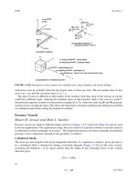
3 Phenomenological Aspects
Experimentally, one seeks to characterize materials by performing simple laboratory tests from
which information relevant to actual in-use conditions may be obtained. In the case of vis-
coelastic materials, mechanical characterization often consists of performing uniaxial tensile
tests similar to those used for elastic solids, but modified so as to enable observation of the
time dependency of the material response. Although many such “viscoelastic tensile tests” have
been used, one most commonly encounters only three: creep, stress relaxation, and dynamic
(sinusoidal) loading.
Creep
The creep test consists of measuring the time dependent strain (t)=δ(t)/L
0
resulting from
the application of a steady uniaxial stress σ
0
as illustrated in Fig. 3. These three curves are the
strains measured at three different stress levels, each one twice the magnitude of the previous
one.
Figure 3: Creep strain at various constant stresses.
Note in Fig. 3 that when the stress is doubled, the resulting strain in doubled over its full
range of time. This occurs if the materials is linear in its response. If the strain-stress relation
is linear, the strain resulting from a stress aσ,wherea is a constant, is just the constant a times
the strain resulting from σ alone. Mathematically,
(aσ)=a(σ)
This is just a case of “double the stress, double the strain.”
If the creep strains produced at a given time are plotted as the abscissa against the applied
stress as the ordinate, an “isochronous” stress-strain curve would be produced. If the material
is linear, this “curve” will be a straight line, with a slope that increases as the chosen time is
decreased.
For linear materials, the family of strain histories (t) obtained at various constant stresses
may be superimposed by normalizing them based on the applied stress. The ratio of strain to
stress is called the “compliance” C, and in the case of time-varying strain arising from a constant
stress the ratio is the “creep compliance”:
C
crp
(t)=
(t)
σ
0
4
A typical form of this function is shown in Fig. 4, plotted against the logarithm of time. Note
that the logarithmic form of the plot changes the shape of the curve drastically, stretching out
the short-time portion of the response and compressing the long-time region. Upon loading,
the material strains initially to the “glassy” compliance C
g
; this is the elastic deformation
corresponding to bond distortion. In time, the compliance rises to an equilibrium or “rubbery”
value C
r
, corresponding to the rubbery extension of the material. The value along the abscissa
labeled “log τ” marks the inflection from rising to falling slope, and τ is called the “relaxation
time” of the creep process.
Figure 4: The creep compliance function C
crp
(t).
Stress relaxation
Another common test, easily conducted on Instron or other displacement-controlled machines,
consists of monitoring the time-dependent stress resulting from a steady strain as seen in Fig. 5.
This is the converse of Fig. 3; here the stress curves correspond to three different levels of
constant strain, each one twice the magnitude of the previous one.
Figure 5: Measurement of relaxation response.
Analogously with creep compliance, one may superimpose the relaxation curves by means
of the “relaxation modulus,” defined as E
rel
(t)=σ(t)/
0
, plotted against log time in Fig. 6.
At short times, the stress is at a high plateau corresponding to a “glassy” modulus E
g
,and
5
then falls exponentially to a lower equilibrium “rubbery” modulus E
r
as the polymer molecules
gradually accommodate the strain by conformational extension rather than bond distortion.
Figure 6: The stress relaxation modulus E
rel
(t). Here E
g
= 100,E
r
=10, and τ =1.
Creep and relaxation are both manifestations of the same molecular mechanisms, and one
should expect that E
rel
and C
crp
are related. However even though E
g
=1/C
g
and E
r
=1/C
r
,in
general E
rel
(t) =1/C
crp
(t). In particular, the relaxation response moves toward its equilibrium
valuemorequicklythandoesthecreepresponse.
Dynamic loading
Creep and stress relaxation tests are convenient for studying material response at long times
(minutes to days), but less accurate at shorter times (seconds and less). Dynamic tests, in which
the stress (or strain) resulting from a sinusoidal strain (or stress) is measured, are often well-
suited for filling out the “short-time” range of polymer response. When a viscoelastic material
is subjected to a sinusoidally varying stress, a steady state will eventually be reached
2
in which
the resulting strain is also sinusoidal, having the same angular frequency but retarded in phase
by an angle δ; this is analogous to the delayed strain observed in creep experiments. The strain
lags the stress by the phase angle δ, and this is true even if the strain rather than the stress is
the controlled variable.
If the origin along the time axis is selected to coincide with a time at which the strain passes
through its maximum, the strain and stress functions can be written as:
=
0
cos ωt (4)
σ = σ
0
cos(ωt + δ)(5)
Using an algebraic maneuver common in the analysis of reactive electrical circuits and other
harmonic systems, it is convenient to write the stress function as a complex quantity σ
∗
whose
real part is in phase with the strain and whose imaginary part is 90
◦
out of phase with it:
σ
∗
= σ
0
cos ωt + iσ
0
sin ωt (6)
Here i =
√
−1 and the asterisk denotes a complex quantity as usual.
2
The time needed for the initial transient effect to die out will itself be dependent on the material’s viscoelastic
response time, and in some situations this can lead to experimental errors. Problem 5 develops the full form of
the dynamic response, including the initial transient term.
6
It can be useful to visualize the observable stress and strain as the projection on the real
axis of vectors rotating in the complex plane at a frequency ω. If we capture their positions just
as the strain vector passes the real axis, the stress vector will be ahead of it by the phase angle
δ as seen in Fig. 7.
Figure 7: The “rotating-vector” representation of harmonic stress and strain.
Figure 7 makes it easy to develop the relations between the various parameters in harmonic
relations:
tan δ = σ
0
/σ
0
(7)
|σ
∗
| = σ
0
=
(σ
0
)
2
+(σ
0
)
2
(8)
σ
0
= σ
0
cos δ (9)
σ
0
= σ
0
sin δ (10)
We can use this complex form of the stress function to define two different dynamic moduli,
both being ratios of stress to strain as usual but having very different molecular interpretations
and macroscopic consequences. The first of these is the “real,” or “storage,” modulus, defined
as the ratio of the in-phase stress to the strain:
E
= σ
0
/
0
(11)
The other is the “imaginary,” or “loss,” modulus, defined as the ratio of the out-of-phase stress
to the strain:
E
= σ
0
/
0
(12)
Example 1
The terms “storage” and “loss” can be understood more readily by considering the mechanical work
done per loading cycle. The quantity
σdis the strain energy per unit volume (since σ = force/area
and = distance/length). Integrating the in-phase and out-of-phase components separately:
W =
σd =
σ
d
dt
dt (13)
=
2π/ω
0
(σ
0
cos ωt)(−
0
ω sin ωt)dt +
2π/ω
0
(σ
0
sin ωt)(−
0
ω sin ωt)dt (14)
7
=0− πσ
0
0
(15)
Note that the in-phase components produce no net work when integrated over a cycle, while the out-of-
phase components result in a net dissipation per cycle equal to:
W
dis
= πσ
0
0
= πσ
0
0
sin δ (16)
This should be interpreted to illustrate that the strain energy associated with the in-phase stress and
strain is reversible; i.e. that energy which is stored in the material during a loading cycle can be re-
covered without loss during unloading. Conversely, energy supplied to the material by the out-of-phase
components is converted irreversibly to heat.
The maximum energy stored by the in-phase components occurs at the quarter-cycle point, and this
maximum stored energy is:
W
st
=
π/2ω
0
(σ
0
cos ωt)(−
0
ω sin ωt)dt
= −
1
2
σ
0
0
= −
1
2
σ
0
0
cos δ (17)
The relative dissipation – the ratio of W
dis
/W
st
– is then related to the phase angle by:
W
dis
W
st
=2π tan δ (18)
We will also find it convenient to express the harmonic stress and strain functions as expo-
nentials:
σ = σ
∗
0
e
iωt
(19)
=
∗
0
e
iωt
(20)
The e
iωt
factor follows from the Euler relation e
iθ
=cosθ + i sin θ, and writing both the stress
and the strain as complex numbers removes the restriction of placing the origin at a time of
maximum strain as was done above. The complex modulus can now be written simply as:
E
∗
= σ
∗
0
/
∗
0
(21)
4 Mathematical Models for Linear Viscoelastic Response
4.1 The Maxwell Spring-Dashpot Model
The time dependence of viscoelastic response is analogous to the time dependence of reactive
electrical circuits, and both can be described by identical ordinary differential equations in time.
A convenient way of developing these relations while also helping visualize molecular motions
employs “spring-dashpot” models. These mechanical analogs use “Hookean” springs, depicted
in Fig. 8 and described by
σ = k
where σ and are analogous to the spring force and displacement, and the spring constant k
is analogous to the Young’s modulus E; k therefore has units of N/m
2
. The spring models
the instantaneous bond deformation of the material, and its magnitude will be related to the
fraction of mechanical energy stored reversibly as strain energy.
8
Figure 8: Hookean spring (left) and Newtonian dashpot (right).
The entropic uncoiling process is fluidlike in nature, and can be modeled by a “Newtonian
dashpot” also shown in Fig. 8, in which the stress produces not a strain but a strain rate:
σ = η ˙
Here the overdot denotes time differentiation and η is a viscosity with units of N-s/m
2
.Inmany
of the relations to follow, it will be convenient to employ the ratio of viscosity to stiffness:
τ =
η
k
The unit of τ is time, and it will be seen that this ratio is a useful measure of the response time
of the material’s viscoelastic response.
Figure 9: The Maxwell model.
The “Maxwell” solid shown in Fig. 9 is a mechanical model in which a Hookean spring and a
Newtonian dashpot are connected in series. The spring should be visualized as representing the
elastic or energetic component of the response, while the dashpot represents the conformational
or entropic component. In a series connection such as the Maxwell model, the stress on each
element is the same and equal to the imposed stress, while the total strain is the sum of the
strain in each element:
σ = σ
s
= σ
d
=
s
+
d
Here the subscripts s and d represent the spring and dashpot, respectively. In seeking a single
equation relating the stress to the strain, it is convenient to differentiate the strain equation and
then write the spring and dashpot strain rates in terms of the stress:
˙ =˙
s
+˙
d
=
˙σ
k
+
σ
η
Multiplying by k and using τ = η/k:
k ˙ =˙σ +
1
τ
σ (22)
This expression is a “constitutive” equation for our fictitious Maxwell material, an equation that
relates the stress to the strain. Note that it contains time derivatives, so that simple constant of
9
proportionality between stress and strain does not exist. The concept of “modulus” – the ratio
of stress to strain – must be broadened to account for this more complicated behavior.
Eqn. 22 can be solved for the stress σ(t) once the strain (t) is specified, or for the strain if
the stress is specified. Two examples will illustrate this process:
Example 2
In a stress relaxation test, a constant strain
0
acts as the “input” to the material, and we seek an
expression for the resulting time-dependent stress; this is depicted in Fig. 10.
Figure 10: Strain and stress histories in the stress relaxation test.
Since in stress relaxation ˙ = 0, Eqn. 22 becomes
dσ
dt
= −
1
τ
σ
Separating variables and integrating:
σ
σ
0
dσ
σ
= −
1
τ
t
0
dt
ln σ −ln σ
0
= −
t
τ
σ(t)=σ
0
exp(−t/τ)
Here the significance of τ ≡ η/k as a characteristic “relaxation time” is evident; it is physically the time
needed for the stress to fall to 1/e of its initial value. It is also the time at which the stress function
passes through an inflection when plotted against log time.
The relaxation modulus E
rel
may be obtained from this relation directly, noting that initially only
the spring will deform and the initial stress and strain are related by σ
0
= k
0
.So
E
rel
(t)=
σ(t)
0
=
σ
0
0
exp(−t/τ)
E
rel
(t)=k exp(−t/τ) (23)
This important function is plotted schematically in Fig. 11. The two adjustable parameters in the model,
k and τ, can be used to force the model to match an experimental plot of the relaxation modulus at two
points. The spring stiffness k would be set to the initial or glass modulus E
g
,andτ would be chosen to
force the value k/e to match the experimental data at t = τ.
10
Figure 11: Relaxation modulus for the Maxwell model.
The relaxation time τ is strongly dependent on temperature and other factors that effect the mobility
of the material, and is roughly inverse to the rate of molecular motion. Above T
g
, τ is very short; below
T
g
, it is very long. More detailed consideration of the temperature dependence will be given in a later
section, in the context of “thermorheologically simple” materials.
Example 3
In the case of the dynamic response, the time dependency of both the stress and the strain are of the
form exp(iωt). All time derivatives will therefore contain the expression (iω)exp(iωt), so Eqn. 22 gives:
k (iω)
∗
0
exp(iωt)=
iω +
1
τ
j
σ
∗
0
exp(iωt)
The complex modulus E
∗
is then
E
∗
=
σ
∗
0
∗
0
=
k(iω)
iω +
1
τ
j
=
k(iωτ)
1+iωτ
(24)
This equation can be manipulated algebraically (multiply and divide by the complex conjugate of the
denominator) to yield:
E
∗
=
kω
2
τ
2
1+ω
2
τ
2
+ i
kωτ
1+ω
2
τ
2
(25)
In Eq. 25, the real and imaginary components of the complex modulus are given explicitly; these are the
“Debye” relations also important in circuit theory.
4.2 The Standard Linear Solid (Maxwell Form)
Most polymers do not exhibit the unrestricted flow permitted by the Maxwell model, although
it might be a reasonable model for Silly Putty or warm tar. Therefore Eqn. 23 is valid only
for a very limited set of materials. For more typical polymers whose conformational change
is eventually limited by the network of entanglements or other types of junction points, more
elaborate spring-dashpot models can be used effectively.
Placing a spring in parallel with the Maxwell unit gives a very useful model known as the
“Standard Linear Solid” (S.L.S.) shown in Fig. 12. This spring has stiffness k
e
, so named because
11
Figure 12: The Maxwell form of the Standard Linear Solid.
it provides an “equilibrium” or rubbery stiffness that remains after the stresses in the Maxwell
arm have relaxed away as the dashpot extends.
In this arrangement, the Maxwell arm and the parallel spring k
e
experience the same strain,
and the total stress σ is the sum of the stress in each arm: σ = σ
e
+ σ
m
.Itisawkwardtosolve
for the stress σ
m
in the Maxwell arm using Eqn. 22, since that contains both the stress and its
time derivative. The Laplace transformation is very convenient in this and other viscoelasticity
problems, because it reduces differential equations to algebraic ones. Appendixes A lists some
transform pairs encountered often in these problems.
Since the stress and strain are zero as the origin is approached from the left, the transforms
of the time derivatives are just the Laplace variable s times the transforms of the functions;
denoting the transformed functions with an overline, we have L(˙)=s
and L (˙σ)=sσ.Then
writing the transform of an expression such as Eqn. 22 is done simply by placing a line over the
time-dependent functions, and replacing the time-derivative overdot by an s coefficient:
k ˙ =˙σ
m
+
1
τ
σ
m
−→ k
1
s = sσ
m
+
1
τ
σ
m
Solving for σ
m
:
σ
m
=
k
1
s
s +
1
τ
(26)
Adding the stress
σ
e
= k
e
in the equilibrium spring, the total stress is:
σ = k
e
+
k
1
s
s +
1
τ
=
k
e
+
k
1
s
s +
1
τ
This result can be written
σ = E (27)
where for this model the parameter E is
E = k
e
+
k
1
s
s +
1
τ
(28)
12
Eqn. 27, which is clearly reminiscent of Hooke’s Law σ = E but in the Laplace plane, is called
the associated viscoelastic constitutive equation. Here the specific expression for E is that of the
Standard Linear Solid model, but other models could have been used as well.
For a given strain input function (t), we obtain the resulting stress function in three steps:
1. Obtain an expression for the transform of the strain function,
(s).
2. Form the algebraic product
σ(s)=E(s).
3. Obtain the inverse transform of the result to yield the stress function in the time plane.
Example 4
In the case of stress relaxation, the strain function (t) is treated as a constant
0
times the “Heaviside”
or “unit step” function u(t):
(t)=
0
u(t),u(t)=
0,t<0
1,t≥ 0
This has the Laplace transform
=
0
s
Using this in Eqn. 27 and dividing through by
0
,wehave
σ
0
=
k
e
s
+
k
1
s +
1
τ
Since L
−1
1/(s + a)=e
−at
, this can be inverted directly to give
σ(t)
0
≡ E
rel
(t)=k
e
+ k
1
exp(−t/τ) (29)
This function, which is just that of the Maxwell model shifted upward by an amount k
e
,wasusedto
generate the curve shown in Fig. 6.
Example 5
The form of Eqn. 27 is convenient when the stress needed to generate a given strain is desired. It is
somewhat awkward when the strain generated by a given stress is desired, since then the parameter E
appears in the denominator:
=
σ
E
=
σ
k
e
+
k
1
s
s+
1
τ
This is more difficult to invert, and in such cases symbolic manipulation software such as Maple
TM
can
be helpful. For instance, if we want to compute the creep compliance of the Maxwell Standard Linear
Solid, we could write:
read transformation library
> with(inttrans):
define governing equation
> eq1:=sigbar=EE*epsbar;
Constant stress sig0:
> sigbar:=laplace(sig0,t,s);
13
EE viscoelastic operator - Maxwell S.L.S. model
> EE:= k[e]+k[1]*s/(s+1/tau);
Solve governing equation for epsbar and invert:
> C[crp](t):=simplify((invlaplace(solve(eq1,epsbar),s,t))/sig0);
k[e] t
-k[e] - k[1] + k[1] exp(- )
tau (k[e] + k[1])
C[crp](t) := -
k[e] (k[e] + k[1])
This result can be written as
C
crp
(t)=C
g
+(C
r
− C
g
)
1 −e
−t/τ
c
(30)
where
C
g
=
1
k
e
+ k
1
,C
r
=
1
k
e
,τ
c
= τ
k
e
+ k
1
k
e
The glassy compliance C
g
is the compliance of the two springs k
e
and k
1
acting in parallel, and the
rubbery compliance C
r
is that of spring k
e
alone, as expected. Less obvious is that the characteristic
time for creep τ
c
(sometimes called the “retardation” time) is longer than the characteristic time for
relaxation τ , by a factor equal to the ratio of the glassy to the rubbery modulus. This is a general result,
not restricted to the particular model used.
A less awkward form for compliance problems is produced when “Voigt-type” rather than Maxwell-
type models are used; see problems 7 and 8.
The Standard Linear Solid is a three-parameter model capable of describing the general
features of viscoelastic relaxation: k
e
and k
1
are chosen to fit the glassy and rubbery moduli,
and τ is chosen to place the relaxation in the correct time interval:
k
e
= E
r
(31)
k
1
= E
g
− E
r
(32)
τ = t @ E
rel
=
E
r
+
1
e
(E
g
− E
r
)
(33)
This forces the S.L.S. prediction to match the experimental data at three points, but the ability
of the model to fit the experimental data over the full range of the relaxation is usually poor.
The relaxation modulus predicted by the S.L.S. drops from E
g
to E
r
in approximately two
decades
3
of time, which is generally too abrupt a transition.
4.3 The Wiechert Model
A real polymer does not relax with a single relaxation time as predicted by the previous mod-
els. Molecular segments of varying length contribute to the relaxation, with the simpler and
shorter segments relaxing much more quickly than the long ones. This leads to a distribution
of relaxation times, which in turn produces a relaxation spread over a much longer time than
14
Figure 13: The Wiechert model.
can be modeled accurately with a single relaxation time. When the engineer considers it nec-
essary to incorporate this effect, the Wiechert model illustrated in Fig. 13 can have as many
spring-dashpot Maxwell elements as are needed to approximate the distribution satisfactorily.
The total stress σ transmitted by the model is the stress in the isolated spring (of stiffness
k
e
) plus that in each of the Maxwell spring-dashpot arms:
σ = σ
e
+
j
σ
j
From Eqn. 26, the stress in the Maxwell arm is
σ
j
=
k
j
s
s +
1
τ
j
Then
σ = σ
e
+
j
σ
j
=
k
e
+
j
k
j
s
s +
1
τ
j
(34)
The quantity in braces is the viscoelastic modulus operator E defined in Eqn. 27 for the Wiechert
model.
Example 6
In stress relaxation tests, we have
(t)=
0
⇒ (s)=
0
/s
σ(s)=E(s)(s)=
k
e
+
j
k
j
s
s +
1
τ
j
0
s
=
k
e
s
+
j
k
j
s +
1
τ
j
0
3
A “decade” of time in our context is a multiple of ten, say from 10
3
to 10
4
seconds, rather than a span of ten
years.
15
σ(t)=L
−1
[σ(s)] =
k
e
+
j
k
j
exp
−t
τ
j
0
(35)
Dividing by
0
, the relaxation modulus is
E
rel
(t)=k
e
+
j
k
j
exp
−t
τ
j
(36)
The material constants in this expression (k
e
and the various k
j
and τ
j
) can be selected by forcing the
predicted values of E
rel
(t) as given by Eqn. 36 to match those determined experimentally. Prob. 19
provides an example of such a procedure.
Example 7
Consider the stress function resulting from a constant-strain-rate test:
= R
t −→ ¯(s)=R
/s
2
where R
is the strain rate. Then
¯σ(s)=E(s)¯(s)=
k
e
+
j
k
j
s
s +
1
τ
j
R
s
2
=
k
e
R
s
2
+
j
k
j
R
s
s +
1
τ
j
σ(t)=k
e
R
t +
j
k
j
R
τ
j
[1 −exp(−t/τ
j
)] (37)
Note that the stress-time function, and hence the stress-strain curve, is not linear. It is not true, therefore,
that a curved stress-strain diagram implies that the material response is nonlinear. It is also interesting to
note that the slope of the constant-strain-rate stress-strain curve is related to the value of the relaxation
modulus evaluated at the same time:
dσ
d
=
dσ
dt
·
dt
d
=
dσ
dt
·
1
R
=
k
e
R
+
j
k
j
R
exp(−t/τ
j
)
1
R
=
k
e
+
j
k
j
exp(−t/τ
j
)
≡ E
rel
(t) |
t=/R
(38)
Example 8
It may be that the input strain function is not known as a mathematical expression, or its mathematical
expression may be so complicated as to make the transform process intractable. In those cases, one may
return to the differential constitutive equation and recast it in finite-difference form so as to obtain a
numerical solution. Recall that the stress in the jth arm of the Wiechert model is given by
dσ
j
dt
+
1
τ
j
σ
j
= k
j
d
dt
(39)
This can be written in finite difference form as
16
σ
t
j
− σ
t−1
j
∆t
+
1
τ
j
σ
t
j
= k
j
t
−
t−1
∆t
(40)
where the superscripts t and t −l indicate values before and after the passage of a small time increment
∆t.Solvingforσ
t
j
:
σ
t
j
=
1
1+(∆t/τ
j
)
k
j
(
t
−
t−1
)+σ
t−1
j
(41)
Now summing over all arms of the model and adding the stress in the equilibrium spring:
σ
t
= k
e
t
+
j
k
j
(
t
−
t−1
)+σ
t−1
j
1+(∆t/τ
j
)
(42)
This constitutes a recursive algorithm which the computer can use to calculate successive values of σ
t
beginning at t = 0. In addition to storing the various k
j
and τ
j
which constitute the material description,
the computer must also keep the previous values of each arm stress (the σ
t−1
j
) in storage.
4.4 The Boltzman Superposition Integral
As seen in the previous sections, linear viscoelasticity can be stated in terms of mechanical models
constructed from linear springs and dashpots. These models generate constitutive relations that
are ordinary differential equations; see Probs. 13 and 14 as examples of this. However, integral
equations could be used as well, and this integral approach is also used as a starting point for
viscoelastic theory.
Integrals are summing operations, and this view of viscoelasticity takes the response of the
material at time t to be the sum of the responses to excitations imposed at all previous times.
The ability to sum these individual responses requires the material to obey a more general
statement of linearity than we have invoked previously, specifically that the response to a number
of individual excitations be the sum of the responses that would have been generated by each
excitation acting alone. Mathematically, if the stress due to a strain
1
(t)isσ(
1
) and that due
to a different strain
2
(t)isσ(
2
), then the stress due to both strains is σ(
1
+
2
)=σ(
1
)+σ(
2
).
Combining this with the condition for multiplicative scaling used earlier, we have as a general
statement of linear viscoelasticity:
σ(a
1
+ b
2
)=aσ(
1
)+bσ(
2
) (43)
The “Boltzman Superposition Integral” statement of linear viscoelastic response follows from
this definition. Consider the stress σ
1
(t)attimet due to the application of a small strain ∆
1
applied at a time ξ
1
previous to t; this is given directly from the definition of the relaxation
modulus as
σ
1
(t)=E
rel
(t − ξ
1
)∆
1
Similarly, the stress σ
2
(t) due to a strain increment ∆
2
applied at a different time ξ
2
is
σ
2
(t)=E
rel
(t − ξ
2
)∆
2
If the material is linear, the total stress at time t due to both strain increments together can be
obtained by superposition of these two individual effects:
17