Engineering - Materials Selection in Mechanical Design Part 10 pptx
Bạn đang xem bản rút gọn của tài liệu. Xem và tải ngay bản đầy đủ của tài liệu tại đây (803.41 KB, 18 trang )
10.1 Introduction and synopsis
These case studies illustrate how the techniques described in the previous chapter really work. Two
'were sketched out there: the light, stijJ; strong beam, and the light, cheap, stiff beam. Here we
develop four more. The first pair illustrate multiple constraints; here the active constraint method is
used. The second pair illustrate compound objectives; here a value function containing an exchange
constant. £$, is formulated. The examples are deliberately simplified to avoid clouding the illustra-
tion with unnecessary detail. The simplification is not nearly as critical as it may at first appear:
the choice of material is determined primarily by the physical principles of the problem, not by
details of geometry .The principles remain the same when much of the detail is removed so that
the selection is largely independent of these.
Further case studies can be found in the sources listed under Further reading.
con-rods for
10.2 Multiple constraints -
high-performance engines
A connecting rod in a high perfonnance engine, compressor or pump is a critical component: if
it fails, catastrophe follows. Yet -to minimize inertial forces and bearing loads -it must weigh
as little as possible, implying the use of light, strong materials, stressed near their limits. When
cost, not perfonnance, is the design goal, con-rods are frequently made of cast iron, because it is
so cheap. But what are the best materials for con-rods when performance is the objective?
The model
Table 10.1 sultlmarizes the design requirements for a connecting rod of minimum weight with
two constraints: that it must carry a peak load F without failing either by fatigue or by buckling
elastically. For simplicity, we assume that the shaft has a rectangular section A = bw (Figure 10.1).
The objective function is an equation for the mass which we approximate as
m = fJALp
(10.1)
where L is the length of the con-rod and p the density of the material of which it is made, A the
cross-section of the shaft and .8 a constant multiplier to allow for the mass of the bearing housings.
Case studies: multiple constraints
and compound objectives
10.1
Introduction and synopsis
Case studies: multiple constraints and compound objectives
229
Table
10.1
The design requirements: connecting rods
Function
Objective Minimize
mass
Constraints
Connecting rod for reciprocating engine or pump
(a) Must not fail
by
high-cycle fatigue, or
(b)
Must not fail
by
elastic buckling
(c) Stroke, and thus con-rod length
L,
specified
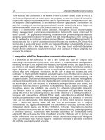
Fig. 10.1
A
connecting rod. The rod must not buckle, fail by fatigue or
by fast fracture (an example of multiple constraints). The objective is
to
minimize mass.
The fatigue constraint requires that
F
A-
-
<
0,
(10.2)
where
CT~
is the endurance limit
of
the material of which the con-rod
is
made. (Here, and elsewhere,
we omit the safety factor which would normally enter an equation
of
this
sort,
since it does not
influence the selection.) Using equation
(10.2)
to eliminate
A
in
equation
(10.1)
gives the mass
of
a
con-rod which will just meet the fatigue constraint:
ml
=
BFL
(:)
(10.3)
pi
MI
=
-
(10.4)
The buckling constraint requires that the peak compressive load
F
does not exceed the Euler
containing the material index
buckling load:
n2EI
L2
F5-
(1
0.5)
with
I
=
b’w/12.
Writing
b
=
aw,
where
w
is
a dimensionless ‘shape-constant’ characterizing the
proportions
of
the cross-section, and eliminating
A
from equation
(10.1)
gives
a
second equation
for the mass
(10.6)
12F
‘I2
m:=B(-)
an2
L’&)
230
Materials Selection in Mechanical Design
containing the material index (the quantity we wish to maximize to avoid buckling):
M*
=
~
(10.7)
rn
The con-rod,
to
be safe, must meet both constraints. For a given stroke, and thus length,
L,
the
active constraint
is
the one leading to the largest value of the mass,
m.
Figure 10.2 shows the way
in which
m
varies with
L
(a sketch of equations (10.3) and (10.6)), for a single material: short
con-rods are liable to fatigue failure, long ones are prone to buckle.
The selection: analytical method
Consider first the selection of a material for the con-rod from among those listed in Table 10.2. The
specifications are
L=
150~
F=50kN
~r=O.5
B=
1
Fig.
10.2
The equations for the mass
m
of the con-rod are
shown
schematically as a function
of
L.
Table
10.2
Selection
of
a material for the con-rod
Material
P
E
5,
ml
m2
+I
kg/m3
GPa MPa
kg
kg
kg
Nodular cast
iron
7150 178 250
0.21
0.13 0.21
HSLA steel 4140
(0.q.
T-315) 7850 210
590
0.1
0.13
0.13
AI
539.0 casting
alloy
2700
70 75
0.27
0.08 0.27
Duralcan
AI-SiC(p) composite 2880
110
230
0.09
0.07
0.09
Ti-6-4 4400 115 530
0.06
0.1
0.1
Case studies: multiple constraints and compound objectives
231
The table lists the mass
ml
of
a
rod which will just meet the fatigue constraint, and the mass
m2
which will just meet that on buckling (equations (10.3) and (10.6)). For three of the materials the
active constraint is that of fatigue; for two it is that of buckling. The quantity
ii
in the last column
of the table is the larger of
ml
and
m2
for each material; it is the lowest mass which meets both
constraints. The material offering the lightest rod is that with the smallest value of
&.
Here it
is
the metal-matrix composite Duralcan 6061-20% SiC(p). The titanium alloy is
a
close second. Both
weigh about half
as
much
as
a
cast-iron rod.
The selection: graphical method
The mass of the rod which will survive both fatigue and buckling is the larger of the two masses
ml
and
m2
(equations (10.3) and (10.6)). Setting them equal gives the equation of the coupling line:
M2
=
[(E)
T2,
F
”*]
M,
(10.8)
The quantity in square brackets
is
tbe coupling constant: it contains the quantity
F/L2
-
the
‘structural loading coefficient’ of Chapter 5.
Materials with the optimum combination of
MI
and
M2
are identified by creating
a
chart with
these indices
as
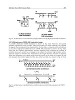
axes. Figure
10.3
illustrates this, using
a
database of light alloys. Coupling lines
for two values of
FIL’
are plotted on it, taking
a
=
0.5. Two extreme selections are shown, one
isolating the best subset when the structural loading coefficient
F/L2
is high, the other when it
is
low. For the high value
(F/L2
=
0.5 MPa), the best materials are high-strength Mg-alloys, followed
by high-strength Ti-alloys. For the low value
(FIL’
=
0.05 MPa), beryllium alloys are the optimum
choice. Table
10.3
lists the conclusions.
Postscript
Con-rods have been made from all the materials in the table: aluminium and magnesium in family
cars, titanium and (rarely) beryllium in racing engines. Had we included CFRP in the selection, we
would have found that it. too, performs well by the criteria we have used. This conclusion has been
reached by others, who have tried to do something about it: at least three designs of CFRP con-rods
have been prototyped. It is not easy to design a CFRP con-rod. It is essential to use continuous
fibres, which must be wound in such
a
way
as
to create both the shaft and the bearing housings;
and the shaft must have
a
high proportion of fibres which lie parallel to the direction in which
F
acts.
You
might,
as
a
challenge, devise how you would do it.
Table
10.3
Materials for high-performance con-rods
Material
Comrnen
t
~~~~~~ ~ ~
Magnesium alloys
Titanium alloys
Beryllium alloys
Aluminium alloys
ZK
60
and
related alloys offer good all-round
performance.
Ti-6-4 is the best choice for high
F/L2.
The ultimate choice when
F/L2
is small. Difficult
to process.
Cheaper than titanium or magnesium,
but
lower
performance.
232
Materials Selection in Mechanical Design
Fig.
10.3
Over-constrained design leads to two or more performance indices linked by coupling
equations. The diagonal broken lines show the coupling equations for two values
of
the coupling
constant, determined by the ‘structural loading coefficient’
F/L2.
The two selection lines must intersect
on the appropriate coupling line giving the box-shaped search areas. (Figure created using
CMS
(1995)
software.)
Related
case
studies
Case Study
10.3:
Multiple constraints
-
windings for high field magnets
10.3
Multiple constraints
-
windings for high field
magnets
Physicists, for reasons
of’
their own, like to see what happens to things in high magnetic fields.
‘High’ means
50
tesla or more. The only way to get such fields is the old-fashioned one: dump
a
huge current through a wire-wound coil; neither permanent magnets (practical limit:
1.5T),
nor
super-conducting coils (present limit:
25T)
can achieve such high fields. The current generates a
field-pulse which lasts
as
long as the current flows. The upper limits on the field and its duration
are set by the material
of
the coil itself if the field is too high, the coil blows itself apart; if too
long, it melts.
So
choosing the right material for the coil is critical. What should
it
be? The answer
depends
on
the pulse length.
Case studies: multiple constraints and compound objectives
233
Table
10.4
Duration and strengths of pulsed fields
Classijcatinn
Duration
Field
strength
Continuous
1
s 00
t30
T
Long looms-1
s
30-60T
Standard
10-
100
ms
40-70T
Short
10-
1000
ps
70-80T
Ultra-short
0.1
-
10
ps
>100T
Pulsed fields are classified according to their duration and strength as in Table
10.4.
The
model
The magnet is shown, very schematically, in Figure
10.4.
The coils are designed to survive the
pulse, although not
all
do. The requirements for survival are summarized in Table
10.5.
There is
one objective
-
to maximize the field
-
with two constraints which derive from the requirement
of survivability for a given pulse length.
Consider first destruction by magnetic loading. The field,
B
(units: weber/m2), in a long solenoid
like that of Figure
10.4
is:
(10.9)
ILoNih.
F
B=-
.f
(Q,
B)
e
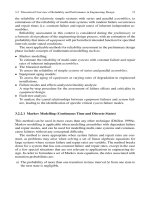
Fig. 10.4
Windings for high-powered magnets. There are two constraints: the magnet must not overheat;
and it must not fail under the radial magnetic forces.
234
Materials Selection in Mechanical Design
Table
10.5
The design requirements: high field magnet
Function Magnet windings
Objective Maximize magnetic field
Constraints (a)
No
mechanical failure
(b) Temperature rise
<
150°C
(c) Radius
R
and length
l
of
coil
specified
where
po
is the permeability of air (437
x
lop7
Wb/Am),
N
is the number of turns,
i
is the current,
k!
is the length of the coil,
hf
is the filling-factor which accounts for the thickness of insulation
(Af
=
cross-section
of
conductor/cross section of coil), and
F(a,
B)
is a geometric constant (the
‘shape factor’) which depends on the proportions of the magnet (defined on Figure 10.4), the value
of which need not concern
us.
The field creates a force on the current-carrying coil. It acts radially
outwards, rather like the pressure in
a
pressure vessel, with a magnitude
(10.10)
though it is actually
a
body force, not a surface force. The pressure generates a stress
u
in the
windings and their casing
PR
B2
R
u=-=
d
2P.,F(U,
BG
This must not exceed the yield strength
uy
of the windings, giving the first limit on
B:
R
Bl
5
The field is maximized by maximizing
(10.1
1)
(10.12)
I
M1=*,.
I
(10.13)
One could have guessed this: the best material to carry
a
stress
0
is that with the largest yield
strength
cy.
Now consider destruction by overheating. High-powered magnets are initially cooled in liquid
nitrogen
to
-
196°C in order to reduce the resistance of the windings;
if
the windings warm above
room temperature, the resistance,
Re,
in general, becomes too large. The entire energy
of
the pulse,
J
i2R,
dt
=
i2R,tp is converted into heat (here
Re
is the average of the resistance over the heating
cycle and
tp
is the length of the pulse); and since there is insufficient time for the heat to be
conducted away, this energy causes the temperature of the coil to rise by
AT,
where
(10.14)
Here
pe
is the resistivity of the material,
C,
its specific heat (Jkg
K)
and p its density. The resistance
of
the coil,
Re,
is related to the resistivity of the material of the windings by
Case studies: multiple constraints and compound objectives
235
where
d
is the diameter of the conducting wire. If the upper limit for the temperature is
200K,
AT,,,
5
100K, giving the second limit on
B:
112
B2
i
(iLid2CpPkf
ATmax
)
F(a,B>
(10.15)
tp
Pe
The field is maximized by maximizing
pq
M2
=
~ (10.16)
The two equations for B are sketched, as a function of pulse-time,
t,,
in Figure 10.5. For short
pulses, the strength constraint is active; for long ones, the heating constraint is dominant.
The
selection: analytical method
Table 10.6 lists material properties for three alternative windings. The sixth column gives the
strength-limited field strength,
B1;
the seventh column, the heat-limited field B2 evaluated for
the following values of the design requirements:
t,
=
1Oms
kf
=
0.5
AT,,,
=
lOOK
F(a,
p)
=
1
R
=
0.05m
d
=
O.1m
Strength
is
the active constraint for the copper-based alloys; heating for the steels. The last column
lists the limiting field
B
for the active constraint. The
Cu-Nb
composites offer the largest
8.
Fig.
10.5
The two equations
for
B
are sketched, indicating the active constraint.
236
Materials Selection in Mechanical Design
Table
10.6
Selection of a material for a high field magnet, pulse length 10 ms
Material
P
BY
CP
Pe
B1 B2
B
High-conductivity copper 8.94 250 38.5
1.7 35
113
35
Mg/m3
MPa
J/kgK
lO@Qm
Wb/m2 Wb/m2
Wb/m2
Cu-1.5%
Nb
composite 8.90 780
368 2.4 62 92
62
HSLA
steel 7.85 1600
450 2.5
89 30 30
The selection: graphical method
The cross-over lies along the line where equations (10.12) and
(1
0.15) are equal, giving the coupling
the line
(10.17)
PoRdh
f
F(a,
B>ATmax
<I
The quantity in square brackets is the coupling constant; it depends on the pulse length,
t,.
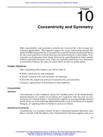
Fig. 10.6
Materials for windings for high-powered magnets, showing the selection for long pulse
applications, and for short pulse ultra-high field applications. (Figure created using
CMS
(1
995)
software.)
Case studies: multiple constraints and compound objectives
237
Table
10.7
Materials for high field magnet windings
Material
Comment
Continuous and
long
pulse
High conductivity coppers
Pure silver
Best choice for low field, long pulse
magnets (heat-limited).
Short pulse
Copper-AL20s composites (Glidcop)
H-C copper cadmium alloys
H-C copper zirconium alloys
H-C copper chromium alloys
Drawn copper-niobium composites
Ultra short
pulse,
ultra high field
Copper- beryllium-cobalt alloys
High-strength, low-alloy steels magnets (strength-limited).
Best choice for high field, short pulse
magnets (heat and strength limited).
Best choice for high field, short pulse
The selection is illustrated in Figure 10.6. Here we have used a database of
conductors:
it is
an example of sector-specific database (one containing materials and data relevant to a specific
industrial sector, rather than one that is material class-specific). The axes are the two indices
M1
and
M2.
Three selections are shown, one for very short-pulse magnets, the other for long pulses.
Each selection box is a contour of constant field,
B;
its corner lies on the coupling line for the
appropriate pulse duration. The best choice, for a given pulse length, is that contained in the box
which lies farthest up its coupling line. The results are summarized in Table 10.7.
Postscript
The case study, as developed here, is an oversimplification. Magnet design, today, is very sophisti-
cated, involving nested sets of electro and super-conducting magnets (up to
9
deep), with geometry
the most important variable. But the selection scheme for coil materials has validity: when pulses
are long, resistivity is the primary consideration; when they are very short, it is strength, and the
best choice for each
is
that developed here. Similar considerations enter the selection of materials
for very high-speed motors, for bus-bars and for relays.
Further reading
Herlach,
F.
(1988)
The technology
of
pulsed high-field magnets,
ZEEE
Transactions
on
Magnetics,
24,
1049.
Wood, J.T., Embury, J.D. and Ashby,
M.F.
(1995)
An approach to material selection
for
high field magnet
design, submitted to
Acta Metal. et Mater.
43,
212.
Related case studies
Case Study
10.2:
Multiple constraints
-
con-rods
10.4
Compound objectives
-
materials
for
insulation
The objective in insulating a refrigerator (of which that sketched in Figure 10.7 is one class
-
there
are many others) is to minimize the energy lost from it, and thus the running cost. But the insulation
238
Materials Selection in Mechanical Design
Fig.
10.7
Insulation for refrigerators. The objectives are to minimize heat
loss
from the interior and to
minimize the
cost
of
the
insulation itself.
itself has a capital cost associated with it. The most economical choice of material for insulation
is that which minimizes the total. There is at least one constraint: an upper limit on the thickness
x,,,
of the insulation (Table 10.8).
The
model
The first objective is to minimize the cost of the insulation. This cost, per unit area of wall,
is
C
=
XmaxPCm
(10.18)
Here
C,
is the
costkg
of
the insulation and
p
is its density.
(W/m2), assuming steady-state heat flow, is
The second objective is
to
minimize the energy
loss.
The heat flux per
unit
area
of
wall,
Q
dT hAT
Q
=
-A
-
=
__
d~
xmax
where
h
(W/m
K)
is
its thermal conductivity and
AT
is the temperature difference between the inside
and the outside of the insulation layer.
If
the refrigerator runs continuously, the energy consumed
Table
10.8
Design requirement for refrigerator insulation
-
Function Thermal insulation
Objectives
Constraint Thickness
5
x,,
(a)
Minimize insulation cost
and
(b)
Minimize energy
loss,
appropriately coupled
Case studies: multiple constraints and compound objectives
239
in
time
t(s)
is
H
=
Qt
(J/m')
We identify
t
with the design life of the refrigerator.
To minimize both objectives in a properly couple way we create a value-function, V,
v= -C+E$H
(10.19)
with
C
given by equation
(10.18)
and
H
by (10.19). It contains the exchange constant, E$, relating
energy to cost. It can vary widely (Table
9.5).
If grid-electricity is available.
E$
is low. But in
remote areas (requiring power-pack generation), in aircraft (supplementary turbine generator) or
in space (solar panels),
it
can be far higher. (The exchange constant relating value to cost is
-1,
giving the negative sign.) Inserting equations
(10.18)
and (10.19) gives
v
=
-Xmax[P~ml
+E$
(")
[A]
(10.20)
Xmax
Here the material properties are enclosed
in
square brackets; everything outside these brackets is
fixed by the design.
The selection: analytical method
Take the example
X,,,
=
20mm
AT
=
20C
t
=
1 year
=
31.5
x
lo6
s
E$
=
-0.02
$/MJ
(grid electricity)
giving, for four candidate foams listed
in
Table 10.9, the values
of
V shown in the last column.
value
of
V. It
is
the best choice.
The polystyrene foam is the cheapest to buy, but the phenolic has the largest (least negative)
The selection: graphical method
Define the indices
MI
=
pCm
and
A42
=
h
We rewrite equation (10.18) in the form:
(10.21)
Table
10.9
Value function,
V,
for
thermal insulation
Material
P
h
C,
fl>
C
V
kg/m'
W/mK
$/kg
MPa
$/m'
E$
=
-0.02
$/MJ
Polystyrene
foam
30 0.034
2.0
0.2
1.2
-22.6
Phenolic
foam
35 0.025
4.0
0.2
2.8
-18.6
Polymethacrylimide
foam
50
0.030
27 0.8 27 -45.9
Polyethersulphone foam 90 0.038
18
0.8 32 -56.0
240
Materials Selection in Mechanical Design
Fig.
10.8
Selection
of
insulating materials for refrigerators with different design lives. (Figure
created
using
CMS
(1
997)
software.)
Everything in the equation is specified except the material groups
M1
and
M2.
We seek materials
which maximize
v.
Figure
10.8
shows
MI
plotted against
M2.
Contours of constant
e
appear as
curved lines; the value of
3
increases towards the bottom right. Two sets of contours are shown,
one for long-term insulation with a design life,
t,
of
10
years, the other for short-term refrigeration,
with a value of
t
of
I
month.
To
plot these, we need a value for the term in square brackets. It has
been evaluated using
AT
=
20”C,
xmaX
=
20mm, and
E$
=
-0.02
$/MJ,
as before. For the shorter
design life, the cost of the insulation dominates the value function; then the best choices are simply
the cheapest ones: the low density expanded polystyrene
EPS
(0.03)
for instance*. But for the longer
design life, the second term
on
the right
of
equation (10.21) becomes dominant, and the choice
of
material changes; the contours shown for
t
=
10
years suggest that low-density phenolics might
be
a
good selection, because their conductivity
is
lower than that of the polystyrenes. Table
10.10
summarizes the selection.
Postscript
In many insulation applications the foam is bonded to the inner and outer walls of the refrigerator
to give stiffness: it performs a mechanical as well as
a
thermal function. Then the strength,
oy,
may
also be relevant. The table includes two high-strength foams.
*
On Figure
10.6
the letters identify the material; the number in brackets gives the density in
Mg/m3.
Thus
PS(0.03)
means
‘a
polystyrene foam
with
a density
of
0.03Mg/m3’.
Case studies: multiple constraints and compound objectives
241
Table
10.10
Materials for refrigerator insulation
Material Comment
Short design life
(tl
=
1
month)
Polystyrene (PS) foams, e.g. PS(0.02)
or
PS(O.025)
Polypropylene (PP) foams, e.&. PP(0.02) or PP(0.03)
Long design
l$e
(tc
=
10year.Y)
Phenolic (PHEN) foams, e.g. PHEN(0.035)
Polyurethane (PU) foams, e.g. PU(0.028)
Polystyrene (PS) foams, e.g. PS(0.02) or PS(0.025)
Cost of insulation dominates the
value function; polystyrene and
polypropylene foams are the
best choice because they
are
the
cheapest.
Heat conduction is important in
the value function. The more
expensive phenolics minimize
the value function and are the
best choice.
Of the two, the polymethacrylimide foam gives the largest (least negative) value of
V
Related case studies
Case Study
10.5:
Compound objectives
-
disposable coffee cups
10.5
Compound objectives
-
disposable coffee cups
It is increasingly recognized that the use of materials in engineering carries environmental penalties:
pollution of water and air, solid waste, consumption
of
non-renewable resources and more (collec-
tively called
eco-damage).
One response is to adopt, as a design objective, the minimization of this
damage.
Consider, as an example, the replacement
of
an existing disposable cup (Figure
10.9)
by one
which
is
more environmentally benign. The environmental impact it causes is difficult to quantify.
One component of impact relates to the
energy content
of the material: many aspects of impact (COz
emissions, air-borne particulates) are proportional to this. And energy content
can
be quantified, at
least approximately. We shall use it as a measure
of
environmental impact, to illustrate how it can
be balanced against cost.
Disposable cups are not, at present, recycled,
so
the energy and material they contain are irretriev-
ably lost when they are discarded. To minimiLe the eco-impact (measured now by energy content),
we seek the design which incorporates the least energy to start with. But disposable cups must
also be cheap.
So
we find two conflicting objectives: the environmental goal
of
minimizing energy
content, and the economic one of minimizing cost. There are constraints which must be met: the
cup must be sufficiently stiff that
it
can be picked up without ovalizing severely, and
it
would be
desirable, too, that it also insulates (Table
10.1
I).
We first write a value function for the cup:
V=-C+E
$
qm
(10.22)
Here
C
is the cost
of
the cup,
m
is its mass and
q
the energy content per unit mass of the material
of
which it
is
made. The quantity
E$
is the exchange constant: the value associated with one unit
242
Materials Selection in Mechanical Design
Fig.
10.9
A
disposable hot-drink cup. It must be cheap, stiff and
of
minimum energy-content.
Table
10.1 1
Design requirements for disposable cup
Function Disposable hot-drink cup
Objectives
(a)
Minimize energy-content and
(b)
Minimize cost, appropriately coupled
Constraints (a) Stiff enough
to
be picked up
(b) Thermally insulating
of environmental damage. Values
E$
are, at present, unknown, but by taking extremes its influence
can be explored.
The first term in this equation describes the material cost of the cup. It is the volume of material
it
contains (thought
of
as a cylinder
of
radius
R,
height
h
and wall thickness
t,
closed at one end)
times the cost
C,p
per
unit
volume
(C,n
is the material cost per unit weight and
p
the density):
C
=
C,m
M
(2nRh
+
nR2)tC,p
(10.23)
=
(2a
+
l)nR2tC,p
where
CY
=
h/R the ratio of height-to-radius. The constraint on stiffness requires that ovalization
must not become unacceptable when the cup is loaded across
a
diagonal,
as
in the figure. This
imposes a limit on its stiffness,
S:
F
ClEI aC,Et3
s=-=
-
-
’
sc
(10.24)
Here
I
is
the second moment
of
area of the wall
of
the cup (proportional
to
ht3/12
for
a
wall
of
uniform thickness,
r),
E
is its Young’s modulus,
C1
is
a
constant and
S,
is the critical stiffness
required for safe handling. Solving
for
t
gives
6
R3
1
2R2
1
/3
t:(!%)
(10.25)
Case studies: multiple constraints and compound objectives
243
which, when inserted in equation (10.23), gives the
cost
of the cup:
C
=
C,m
=
(2a
+
l)nR2C,,p
(
;c";;(;.)
"3
or
(10.26)
(1
0.27)
in which the constant C2 contains the design parameters. By
a
similar chain of argument, replacing
C,p
by
qp
(where
q
is the energy per unit mass of the material), the
energy content
of the cup is
qm
=
c2
(S)
(10.28)
If
we now associate
a
cost
E$
with environmental impact as measured by energy content (an energy
tax, for example,
or
a pollution tax), environmental impact can be converted to cost, giving:
v
=
C2[M,
+
E$M2]
(10.29)
with
MI
=
C,p/E'/'
and
Mz
=
qp/E1l3.
The selection: analytical method
Table 10.12 lists three candidates for the cup: foamed polystyrene (PS), polycarbonate
(PC)
and
high density polyethylene
(HDPE),
with the relevant properties. The remaining columns list the
wall thickness, the cost and the value, taking
R=40mm
w=4
C1=24 S,=3kN/m
With no penalty on energy
(Es
=
0),
polystyrene has the greatest value.
A
pollution tax of
0.01
$NJ
leads to the ranking in the second last column; one
of
0.05
$/MJ
gives the values in the last one.
With the higher tax,
PC
becomes more attractive.
We have used numerical values for R,
a,
C1
and
S,
here, but it was not necessary. It is frequently
so
that the optimum selection is independent of some or
all
of
the other variables
of
the design, and
this is
an
example of just that. The variables
R,
a,
C1
and
S,
are all contained in the quantity
C2
of
equation
(10.29),
the value
of
which does not alter the ranking
of
the candidates in Table 10.12:
ranking by
V
or by
V/C?.
Table
10.12
Value functions,
V,
for two values
of
exchange constant,
E$
~ ~~ ~~ ~~
Material
P
E
c:
4
t
C
v,
E$
=
V,
E$
=
Mg/m'
GPa
$/kK
MJAg
mm
$
-0.01
$/MJ
-0.05
$/MJ
Expanded PS
0.05
0.03
1.4
180
2.7 0.009
-0.02
-0.07
Expanded PC
0.065 0.95
5.0
170
1
0.016
-0.02 -0.04
Expanded HDPE
0.08
0.006 1.6 150
4.6 0.3 -0.06 -0.17
*Cost
of
matenal in shape
of
cup, when mass produced, 1s almost the same
a5
that
of
the material itself.
244
Materials
Selection in Mechanical Design
The selection: graphical method
Figure
10.10
shows
MI
plotted against
Mz,
allowing the selection of materials
to
minimize,
in
a
balanced way, both cost and energy content. We will assume that the cups are at present pressed
from
solid polystyrene
(PS)
sheet with
a
density of 1060 kg/m3; it is indicated
as
a black ellipse
on
the figure. The contours show the selection ‘boundary’ for various values
of
E’.
The materials
which lie below the appropriate contour are
a
better choice than the current material: they give a
lower value
of
V
than it does. For small values
of
E$,
the contours are almost vertical; for large
E$
they are almost horizontal.
Materials in the lower-left quadrant are both cheaper
and less energy intensive than the current
material: they are
a
better choice than the existing solid
PS,
regardless
of
the value
of
E$.
Among
these are a range of polyethylene foams, LDPE, with densities in the range
0.018
to 0.029Mg/m3
(LDPE
(0.01
8),
for instance) and the expanded polystyrenes with densities between 0.02 and
0.05 Mg/m3
(EPS
(0.02)
or
EPS
(0.05)). But if the energy tax were high enough
-
if
E$
were as high
as 0.01
$/MJ,
for example
-
then a range of
PVC
foams become potential candidates; and
if
it rose
to
0.1
$/MJ,
cups made of cork
(!)
would become economic. Table 10.13 summarizes the selection.
Further reading
Boustead,
I.
and
Hancock,
G.F.
(1979)
Handbook
of
Industrial Energy Analysis,
Wiley,
New
York.
Fig.
10.10
Comparison
of
polystyrene with competing materials
for
disposable
cups.
(Figure
created
using
CMS
(1
995)
software.)
Case studies: multiple constraints and compound objectives
245
Table
10.13
Materials for
low
energy, cheap coffee cups
Muterial
Cornmeni
Short
design
life
Expanded polystyrene (EPS) foams
[e.g. EPS(0.02) to EPS(0.05)]
Polypropylene (PP) foams
[e.g. PP(0.02) to PP(O.06)]
Polyethylene (LDPE) foams
[e.g.
LDPE(O.018) to LDPE(0.029)]
The best choice: lower cost and energy content
than solid PS; good thermal properties.
A
viable alternative to expanded
PS.
Considerably more expensive and more energy
intensive than expanded PS.
Related case studies
Case Study
10.4:
Compound objectives
-
materials for insulation
10.6
Summary and conclusions
Most designs are over-constrained: they must simultaneously meet several conflicting require-
ments. But although they conflict, an optimum selection is still possible. The ‘active constraint’
method, developed in Chapter
9,
allows the selection of materials which optimally meet two or
more constraints.
It is illustrated here by two case studies, one
of
them mechanical, one electro-
mechanical.
Greater problems arise when the design must meet two or more conflicting objectives (such as
minimizing mass, cost and environmental impact). Here we need a way can be found to express
all the objectives in the same units, a ‘common currency’,
so
to speak. The conversion factor is
called the exchange constant,
E‘.
Establishing the value
of
the exchange constant is an important
step
in
solving the problem. With it, a value function
V
is constructed which combines the objectives.
Materials which minimize
V
meet all the objectives in a properly balanced way. The most obvious
common currency is cost itself, requiring
an
‘exchange rate’ to be established between cost and
the other objectives. This can be done for energy and for mass, and
-
at least
in
principle
-
for
environmental impact. The method is illustrated by two further case studies.