Handbook of Shaft Alignment Part 3 pdf
Bạn đang xem bản rút gọn của tài liệu. Xem và tải ngay bản đầy đủ của tài liệu tại đây (1.63 MB, 50 trang )
.
Gravitational force
.
V-belt or chain tension
.
Shaft misalignment
.
Some types of hydraulic or aerodynamic loads
Dynamic loads on shafts and bearings are caused by some of the following sources (not a
complete list by any means):
.
Out of balance condition (i.e., the center of mass is not coincident with the centerline of
rotation)
.
Eccentric rotor components or bent shafts (another form of unbalance)
.
Damaged antifriction bearings
.
Intermittent, period rubs
.
Gear tooth contact
.
Pump or compressor impeller blades passing by a stationary object
.
Electromagnetic forces
Simply stated, vibration is motion. Vibratory motion in machinery is caused by forces
that change their direction. For example, a rotor that is out of balance and is not
0.5
0.4
0.3
0.2
0.1
0
0 6000 12000 18000 2000 3000
Peak velocity in in/s
DIDstrb P2-MIA Motor Inboard Axial
Frequency in cpm
Before alignment
After alignment
DIDstrb P2-MIA Motor Inboard Axial
0.5
0.4
0.3
0.2
0.1
0
0 6000 12000 18000 2000 3000
Frequency in cpm
DIDstrb P2-POA Pump Outboard Axial DIDstrb P2-POA Pump Outboard Axial
0.5
0.4
0.3
0.2
0.1
0
0.5
0.4
0.3
0.2
0.1
0
0 6000 12000 18000 2000 3000 0 6000 12000 18000 2000 3000
Frequency in cpm Frequency in cpm
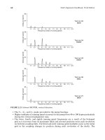
3556.
7191.
FIGURE 2.33 Before and after axial vibration data on motor and pump.
Piotrowski / Shaft Alignment Handbook, Third Edition DK4322_C002 Final Proof page 70 6.10.2006 5:21pm
70 Shaft Alignment Handbook, Third Edition
rotating, does not vibrate. As soon as the imbalanced rotor begins to spin, it also begins
to vibrate. This occurs because the ‘‘heavy spot’’ is changing its position, causing the
(centrifugal) force to change its direction. The rotor=bearing=support system, being
elastic, consequentially begins to flex or move as these alternating forces begin to act
on the machine.
Another detectable vibration pattern exists in gears and is commonly referred to as
gear mesh. Gear mesh can be detected as forces increase or subside as each tooth comes in
contact with another. Other types of mechanical or electrical problems that can be detected
through vibration analysis can be traced back to the fact that forces are somehow changing
their direction.
On the other hand, when two or more shafts are connected together by some flexible or
rigid element where the centerlines of each machine are not collinear, the forces transferred
from shaft to shaft are acting in one direction only. These forces do not change their
direction, as an imbalance condition does. If a motor shaft is higher than a pump shaft
by 50 mils, the motor shaft is trying to pull the pump shaft upward to come in line with the
motor shaft position. Conversely, the pump shaft is trying to pull the motor shaft downward
to come in line with the pump shaft position. The misalignment forces will begin to bend the
shafts, not flutter them around like the tail of a fish.
Static forces caused by misalignment act in one direction only, which is quite different than
the dynamic forces that generate vibration. Under this pretense, how could misalignment ever
cause vibration to occur? If anything, misalignment should diminish the capacity for motion
to occur in a rotor=bearing=support system.
2.2.10 KNOWN VIBRATION SPECTRAL SIGNATURES OF MISALIGNED FLEXIBLE COUPLINGS
Despite the fact that shaft misalignment may decrease the amount of vibration in rotating
machinery, vibration can and does occur due to this condition. As previously mentioned, it
has been observed that the vibration spectral pattern of misaligned rotating machinery
will frequently be different depending on the type of flexible coupling connecting the two
shaft together.
Figure 2.34 through Figure 2.39 show vibration patterns that have been observed on
misaligned rotating machinery with different types of flexible couplings. Notice that the
vibration peaks are occurring at running speed (1X) or multiples of running speed (2X, 3X,
4X, etc.).
2.2.11 VIBRATION CHARACTERISTICS OF MISALIGNED MACHINERY SUPPORTED IN SLIDING
TYPE BEARINGS
The vibration spectral patterns in Figure 2.34 through Figure 2.39 were seen on rotating
machinery supported in rolling element type bearings. Frequently a different pattern emerges
on machinery supported in sliding type bearings as shown in Figure 2.40.
2.2.12 USING INFRARED THERMOGRAPHY TO DETECT MISALIGNMENT
A very interesting study was performed by two maintenance technicians from a bottling
company in 1991. The test was conducted by coupling a 10 hp motor to a 7200 W electric
generator. A specific flexible coupling was installed between the motor and the generator; the
unit was then accurately aligned and then started up. Vibration, ultrasound, and thermal
Piotrowski / Shaft Alignment Handbook, Third Edition DK4322_C002 Final Proof page 71 6.10.2006 5:21pm
Detecting Misalignment on Rotating Machinery 71
imaging data was then collected after 10 min run time. The unit was then shutdown, 10 mils of
shims were placed under all 4 ft of the motor, the drive system started back up and the data
was collected again. This was repeated several times with an additional 10 mils of shims
installed under the motor feet each time. After the motor and generator drive was misaligned
1ϫ 2ϫ 3ϫ 4ϫ 5ϫ 6ϫ 7ϫ 8ϫ 9ϫ 10ϫ
1ϫ 2ϫ 3ϫ 4ϫ 5ϫ 6ϫ 7ϫ 8ϫ 9ϫ 10ϫ
Motor driven ANSI pump
J. Lorenc horizontal misalignment at 90 mils IB & OB
Jaw coupling
Various vibration responses to misalignment
Motor driven generator test
D. Nower horizontal and angular misalignment at 15 mils/in.
FIGURE 2.34 Observed vibration patterns on misaligned jaw-type couplings. (Courtesy of Lovejoy,
Downers Grove, IL. With permission.)
Piotrowski / Shaft Alignment Handbook, Third Edition DK4322_C002 Final Proof page 72 6.10.2006 5:21pm
72 Shaft Alignment Handbook, Third Edition
Motor driven ANSI pump
J. Lorenc horizontal misalignment at 30 mils IB & OB
Gear coupling
Various vibration responses to misalignment
Gas/power turbine driven compressor
J. Piotrowski horizontal misali
g
nment at 65 mils IB & OB
1ϫ 2ϫ 3ϫ 4ϫ 5ϫ 6ϫ 7ϫ 8ϫ 9ϫ 10ϫ
1ϫ 2ϫ 3ϫ 4ϫ 5ϫ 6ϫ 7ϫ 8ϫ 9ϫ 10ϫ
FIGURE 2.35 Observed vibration patterns on misaligned gear type couplings. (Courtesy of Rexmord
Coupling Group, Milwaukee, WI. With permission.)
Piotrowski / Shaft Alignment Handbook, Third Edition DK4322_C002 Final Proof page 73 6.10.2006 5:21pm
Detecting Misalignment on Rotating Machinery 73
Motor driven ANSI pump
S. Chancey vertical misalignment 50 mils at IB & 75 mils at OB
J. Lorenc horizontal misalignment at 90 mils IB & OB
Metal ribbon coupling
Various vibration responses to misalignment
Motor driven generator test
D. Nower horizontal misalignment at 50 mils IB & OB
Motor driven centrifugal pump
J. Piotrowski horizontal misalignment at 36 mils IB & OB
1ϫ 2ϫ 3ϫ 4ϫ 5ϫ 6ϫ 7ϫ 8ϫ 9ϫ 10ϫ
1ϫ 2ϫ 3ϫ 4ϫ 5ϫ 6ϫ 7ϫ 8ϫ 9ϫ 10ϫ
1ϫ 2ϫ 3ϫ 4ϫ 5ϫ 6ϫ 7ϫ 8ϫ 9ϫ 10ϫ
FIGURE 2.36 Observed vibration patterns on misaligned metal ribbon-type couplings. (Courtesy of
Rexmord Coupling Group, Milwaukee, IL. With permission.)
Piotrowski / Shaft Alignment Handbook, Third Edition DK4322_C002 Final Proof page 74 6.10.2006 5:21pm
74 Shaft Alignment Handbook, Third Edition
30–40 mils, the flexible coupling being tested was removed, a different flexible coupling design
was then installed, the shims were removed from the motor to get back to near perfect
alignment, and the process was repeated.
Figure 2.41 through Figure 2.46 show the results of the six different flexible couplings
that were tested. Notice that as the misalignment increased, so too did the temperature
of the coupling or of the flexing element. The increase in temperature is somewhat
linear as illustrated in the temperature graphs with each coupling tested. Disappoint-
ingly, however, the vibration and ultrasound data was never published with the
infrared data.
In addition, there must be a word of caution here because it is very tempting to
make generalizations from this data. Not every flexible or rigid coupling will increase
in temperature when subjected to misalignment conditions. The flexible couplings used in
this test were mechanically flexible couplings (the chain and metal ribbon types) or elasto-
meric types.
In mechanically flexible couplings the heat is generated as the metal grid slides back and
forth across the tooth slots in the coupling hubs or as the chain rollers slide across the
sprocket teeth as the coupling elements attempt to accept the misalignment condition. In
the elastomeric couplings, the elastomer is heated through some sliding friction but pri-
marily by shear and compression forces as these coupling elements attempt to accept their
misalignment conditions.
What would have happened if a flexible disk or diaphragm type coupling was also
tested? Flexible disk or diaphragm couplings accept misalignment conditions by elastically
bending the two disk packs or diaphragms and virtually no heat will be generated by
the flexure of metal disks as these types of couplings attempt to accommodate any
misalignment conditions.
2.2.13 POWER LOSS DUE TO SHAFT MISALIGNMENT
It has been widely publicized that shaft misalignment will cause the driver to work harder and
therefore take more energy or power to run the drive system. However, a study conducted by
the University of Tennessee in 1997 where both 50 and 60 hp motors were purposely misaligned
to dynamometers using four different types of couplings and subjecting each coupling to 15
misalignment conditions came to the following conclusions: ‘‘The results of these tests show
no significant correlation between misalignment and changes in efficiency when the tested
couplings were operated within the manufacturer’s recommended range. Power consumption
and power output remained constant regardless of the alignment condition.’’
2.2.14 THE MOST EFFECTIVE WAY TO DETERMINE IF MISALIGNMENT EXISTS
After years of study, one invariable conclusion can be made. Misalignment disguises itself
very well on the operating rotating machinery. There are no easy or inexpensive ways
to determine if rotating machinery is misaligned while it is running. The most effective way
to determine if a misalignment condition exists is to shut the drive system down, safety tag
and lock out the machinery, remove the coupling guard, and employ one of the alignment
measurement methods described in Chapter 7 to see if a misalignment condition is present.
Even if the alignment looks good when you do an off-line check, running misalignment may
occur. So it is suggested that you also review Chapter 9, which discusses off-line to running
machinery movement.
Piotrowski / Shaft Alignment Handbook, Third Edition DK4322_C002 Final Proof page 75 6.10.2006 5:21pm
Detecting Misalignment on Rotating Machinery 75
Motor driven BFW pump
Motor driven demonstrator
J. Piotrowski horizontal misalignment at 80 mils IB & OB
Flexible disk-type coupling
Various vibration responses to misalignment
Motor driven motor experimental test
D. Dewell parallel at 96 mils
Motor driven generator test
D. Nower horizontal and angular misalignment at 75 mils high
1ϫ 2ϫ 3ϫ 4ϫ 5ϫ 6ϫ 7ϫ 8ϫ 9ϫ 10ϫ
1ϫ 2ϫ 3ϫ 4ϫ 5ϫ 6ϫ 7ϫ 8ϫ 9ϫ 10ϫ
1ϫ 2ϫ 3ϫ 4ϫ 5ϫ 6ϫ 7ϫ 8ϫ 9ϫ 10ϫ
FIGURE 2.37 Observed vibration patterns on misaligned flexible disk-type couplings. (Courtesy of
Thomas Rexnord, Warren, PA. With permission.)
Piotrowski / Shaft Alignment Handbook, Third Edition DK4322_C002 Final Proof page 76 6.10.2006 5:21pm
76 Shaft Alignment Handbook, Third Edition
Motor driven ANSI pump
J. Lorenc horizontal misalignment at 90 mils IB & OB
J. Piotrowski horizontal misalignment at 80 mils IB & OB
Rubber tire-type coupling
Various vibration responses to misalignment
Motor driven generator test
D. Nower horizontal and angular misalignment at 75 mils high
1ϫ 2ϫ 3ϫ 4ϫ 5ϫ 6ϫ 7ϫ 8ϫ 9ϫ 10ϫ
1ϫ 2ϫ 3ϫ 4ϫ 5ϫ 6ϫ 7ϫ 8ϫ 9ϫ 10ϫ
FIGURE 2.38 Observed vibration patterns on misaligned flexible disk-type couplings. (Courtesy of
Dodge-Reliance Electric, Cleveland, OH. With permission.)
Piotrowski / Shaft Alignment Handbook, Third Edition DK4322_C002 Final Proof page 77 6.10.2006 5:21pm
Detecting Misalignment on Rotating Machinery 77
Motor driven pump—Motor IB Hrz
vertical misalignment
Motor was 100 mils high at OB, 46 mils high at IB
Motor driven pump—Pump IB Hrz
vertical misalignment
Motor was 100 mils high at OB, 46 mils high at IB
Motor driven pump—Motor OB Hrz
vertical misalignment
Motor was 100 mils high at OB, 46 mils high at IB
TB Woods-type coupling
various vibration responses to misalignment
1ϫ 2ϫ 3ϫ 4ϫ 5ϫ 6ϫ 7ϫ 8ϫ 9ϫ 10ϫ
1ϫ 2ϫ 3ϫ 4ϫ 5ϫ 6ϫ 7ϫ 8ϫ 9ϫ 10ϫ
1ϫ 2ϫ 3ϫ 4ϫ 5ϫ 6ϫ 7ϫ 8ϫ 9ϫ 10ϫ
FIGURE 2.39 Observed vibration patterns on misaligned flexible disk-type couplings. (Courtesy of T. B.
Woods and Sons, Chambersburg, PA. With permission.)
(continued )
Piotrowski / Shaft Alignment Handbook, Third Edition DK4322_C002 Final Proof page 78 6.10.2006 5:21pm
78 Shaft Alignment Handbook, Third Edition
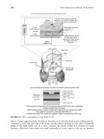
Sliding type
bearing
Force
Proximity
probes
Shaft
When the signals from two proximity probes
are combined together in a two channel
oscilloscope or vibration analyzer, the orbital
motion of the shaft can be observed (called
a Lissajous pattern).
A typical shaft orbit in a sliding type bearing
with no external forces applied to the shaft
is shown to the right. Even if a pure imbalance
condition existed causing an even radial force,
the orbital pattern would be elliptical due to
the different horizontal and vertical stiffnesses
of the machine case.
If a downward force from shaft misalignment
is now applied to the rotor/bearing system,
the elliptical orbit begins to “flatten out”. The
static misalignment force is limiting the
amount of shaft movement in the vertical
direction.
If the force from misalignment increase the
orbit continues to flatten and distort.
As the force begins to steadily increase, the
orbit begins to take a pickle shape.
When the force is great enough, the orbit
changes shape to a figure “8”, hence a 2ϫ
running speed vibration component appears.
FIGURE 2.40 Observed vibration orbital patterns on rotors supported in sliding type bearings.
Piotrowski / Shaft Alignment Handbook, Third Edition DK4322_C002 Final Proof page 79 6.10.2006 5:21pm
Detecting Misalignment on Rotating Machinery 79
(a) (b)
(c)
Temperature (ЊF)
Misalignment(d)
0
50
100
150
0 mils
10 mils
20 mils
30 mils
40 mils
FIGURE 2.41 Observed temperature patterns on misaligned jaw-type coupling. (a) A photograph of
the coupling, (b) an infrared image of the coupling running under good alignment conditions, (c) an
infrared image of the coupling running with the worst misalignment condition (d) temperature of
coupling at each 10 mil misalignment condition. (Photos and data courtesy of Infraspection Institute,
Shelburne, VT.)
Piotrowski / Shaft Alignment Handbook, Third Edition DK4322_C002 Final Proof page 80 6.10.2006 5:21pm
80 Shaft Alignment Handbook, Third Edition
(a)
(c)
(d)
(b)
Temperature (8F)
Misalignment
0
50
100
150
0 mils
10 mils
20 mils
30 mils
40 mils
FIGURE 2.42 Observed temperature patterns on misaligned rubber tire-type coupling. Upper right
photo shows infrared image of coupling running under good alignment conditions. Lower right photo
shows coupling running under ‘‘worst case’’ misalignment condition indicated by rightmost bar on
temperature graph. (Photos and data courtesy of Infraspection Institute, Shelburne, VT.)
Piotrowski / Shaft Alignment Handbook, Third Edition DK4322_C002 Final Proof page 81 6.10.2006 5:21pm
Detecting Misalignment on Rotating Machinery 81
(a)
(c)
(d)
(b)
Temperature (8F)
Misalignment
0
100
200
0 mils
10 mils
20 mils
30 mils
40 mils
FIGURE 2.43 Observed temperature patterns on misaligned rubber insert type coupling. (a) A photo-
graph of the coupling, (b) an infrared image of the coupling running under good alignment conditions,
(c) an infrared image of the coupling running with the worst misalignment condition (d) temperature of
coupling at each 10 mil misalignment condition. (Photos and data courtesy of Infraspection Institute,
Shelburne, VT.)
Piotrowski / Shaft Alignment Handbook, Third Edition DK4322_C002 Final Proof page 82 6.10.2006 5:21pm
82 Shaft Alignment Handbook, Third Edition
(a)
(c)
(b)
(d)
Temperature (8F)
Misalignment
0
50
100
150
0 mils
10 mils
20 mils
30 mils
40 mils
FIGURE 2.44 Observed temperature patterns on misaligned rubber ‘‘gear’’ type coupling. (a) A photo-
graph of the coupling, (b) an infrared image of the coupling running under good alignment conditions,
(c) an infrared image of the coupling running with the worst misalignment condition (d) temperature of
coupling at each 10 mil misalignment condition. (Photos and data courtesy of Infraspection Institute,
Shelburne, VT.)
Piotrowski / Shaft Alignment Handbook, Third Edition DK4322_C002 Final Proof page 83 6.10.2006 5:21pm
Detecting Misalignment on Rotating Machinery 83
(a)
(c)
(d)
(b)
0
50
100
150
Temperature (8F)
Misalignment
0 mils
10 mils
20 mils
30 mils
40 mils
FIGURE 2.45 Observed temperature patterns on misaligned metal ribbon-type coupling. (a) A photo-
graph of the coupling, (b) an infrared image of the coupling running under good alignment conditions,
(c) an infrared image of the coupling running with the worst misalignment condition (d) temperature of
coupling at each 10 mil misalignment condition. (Photos and data courtesy of Infraspection Institute,
Shelburne, VT.)
Piotrowski / Shaft Alignment Handbook, Third Edition DK4322_C002 Final Proof page 84 6.10.2006 5:21pm
84 Shaft Alignment Handbook, Third Edition
(a)
(c)
(b)
(d)
Temperature (8F)
Misalignment
0
50
100
150
0 mils
10 mils
20 mils
30 mils
40 mils
FIGURE 2.46 Observed temperature patterns on misaligned chain type coupling. (a) A photograph of
the coupling, (b) an infrared image of the coupling running under good alignment conditions, (c) an
infrared image of the coupling running with the worst misalignment condition (d) temperature of
coupling at each 10 mil misalignment condition. (Photos and data courtesy of Infraspection Institute,
Shelburne, VT.)
Piotrowski / Shaft Alignment Handbook, Third Edition DK4322_C002 Final Proof page 85 6.10.2006 5:21pm
Detecting Misalignment on Rotating Machinery 85
BIBLIOGRAPHY
Alignment Loading of Gear Type Couplings, Application Notes no. (009)L0048, Bently Nevada
Corporation, Minden, NV, March 1978.
Audio Visual Customer Training—Instruction Manual, IRD Mechanalysis Inc., Publication no. 414E,
Columbus, OH, 1975.
Baxter, N.L., Vibration and Balance Problems in Fossil Plants: Industry Case Histories, Electric Power
Research Institute, Palo Alto, CA, publication no. CS-2725, Research Project no. 1266-27,
November 1982.
Bertin, C.D. and Buehler, M.W., Typical vibration signatures—case studies, Turbomachinery Inter-
national, October 1983, pp. 15–21.
Bond, T., Application Update—Deltaflex Coupling—Vibration Analysis: Motor to Centrifugal Pump,
Lovejoy Inc., October 1992, personal correspondence.
Daintith, E. and Glatt, P., Reduce costs with laser shaft alignment, Hydrocarbon Processing, August
1996.
Dewell, D.L. and Mitchell, L.D., Detection of a misaligned disk coupling using spectrum analysis,
Journal of Vibration, Acoustics, Stress, and Reliability in Design (1984), 106, 9–16.
Eshleman, R.L., Torsional Vibration of Machine Systems, Proceedings of the Sixth Turbomachinery
Symposium, December 1977, Gas Turbine Labs, Texas A&M University, College Station, TX.
Eshleman, R.L., Effects of Misalignment on Machinery Vibrations, Proceedings of the Balancing=Align-
Alignment of Rotating Machinery, February 23–26, 1982, Galveston, TX, Vibration Institute,
Clarendon Hills, IL.
Eshleman, R.L., The Role of Couplings in the Vibration of Machine Systems, Vibration Institute
Meeting, Cincinnati Chapter, November 3, 1983.
Ganeriwala, S., Patel, S., and Hartung, H.A., The Truth Behind Misalignment Vibration Spectra of
Rotating Machinery, SpectraQuest Inc., Richmond, VA, 2003.
Jackson, C., The Practical Vibration Primer, Gulf Publishing Company, Houston, TX, 1979.
Kueck, J.D., Casada, D.A., and Otaduy, P.J., A comparison of two energy efficient motors, P=PM
Technology, April 1996.
Ludeca Inc., Maintenance Study, Evaluating Energy Consumption on Misaligned Machines, Doral, FL,
1994.
Mannasmith, J. and Piotrowski, J.D., Machinery Alignment Methods and Applications, Vibration
Institute Meeting, Cincinnati Chapter, September 8, 1983.
Nower, D., Misalignment: challenging the rules, Reliability Magazine (1994), 38–43.
Nower, D., Alignment Tolerances—Why Use Them? 1996 Vibration Institute Meeting Proceedings,
pp. 179–184.
Piotrowski, J.D., How Varying Degrees of Misalignment Affect Rotating Machinery—A Case Study,
Proceedings of the Machinery Vibration Monitoring and Analysis Meeting, June 26–28, 1984,
New Orleans, LA, Vibration Institute, Clarendon Hills, IL.
Piotrowski, J.D., Aligning Cooling Tower Drive Systems, Proceedings of the Machinery Vibration
Monitoring and Analysis, Ninth Annual Meeting, May 20–24, 1985, New Orleans, LA, Vibration
Institute, Clarendon Hills, IL.
Schultz, J. and Friebel, D., The business case for reliability, Reliability (2002), 8(6).
Sohre, J.S., Turbomachinery Analysis and Protection, Proceedings of the First Turbomachinery Sympo-
sium, Gas Turbine Labs, Texas A&M University, College Station, TX, 1972.
Weiss, W., Laser alignment saves amps, dollars, Plant Services, April 1991.
Wesley J.H., Edmondson, A., Carley, J., Nower, D., Kueck, J., Jesse, S., and Kuropatwinski, J.J.,
Motor Shaft Misalignment and Detection—Phase 1, July 20, 1997, Maintenance and Reliability
Center, College of Engineering, University of Tennessee, Knoxville, TN.
Xu, M. and Marangoni, R.D., Vibration analysis of a motor—flexible coupling—rotor system subject
to misalignment and unbalance, Part I: Theoretical model and analysis, Journal of Sound and
Vibration (1994a), 176(5), 663–679.
Piotrowski / Shaft Alignment Handbook, Third Edition DK4322_C002 Final Proof page 86 6.10.2006 5:21pm
86 Shaft Alignment Handbook, Third Edition
Xu, M. and Marangoni, R.D., Vibration analysis of a motor—flexible coupling—rotor system subject
to misalignment and unbalance, Part II: Experimental validation, Journal of Sound and Vibra-
tion (1994b), 176(5), 681–691.
Xu, M., Zatezalo, J.M., and Marangoni, R.D., Reducing power loss through shaft alignment, P=PM
Technology, October 1993.
Piotrowski / Shaft Alignment Handbook, Third Edition DK4322_C002 Final Proof page 87 6.10.2006 5:21pm
Detecting Misalignment on Rotating Machinery 87
Piotrowski / Shaft Alignment Handbook, Third Edition DK4322_C002 Final Proof page 88 6.10.2006 5:21pm
3
Foundations, Baseplates,
Installation, and Piping Strain
Every rotating machinery drive system requires some kind of supporting structure to hold it
in position. Imagine for a moment, the design concerns for machinery that is located near a
river or a lake, on top of an underground aquifer, near a busy highway, in the middle of a
swamp, operating on seagoing vessels, offshore oil and gas platforms, or on the 18th floor of
an office complex. The foundations and support structures not only have to bear the weight
of the machinery but also have to be designed to maintain a stable position if the machinery
begins to vibrate. Frequently alignment problems can be traced back to design, installation,
or deterioration problems with the foundation, base or soleplate, or the machine housings
themselves. It is going to be not only difficult to obtain accurate alignment initially but also
equally difficult to maintain satisfactory alignment over long periods of time if the machinery
is sitting on unstable or improperly designed foundations and frames.
Not all, but a large percentage of rotating machinery sits on or is somehow attached to the
ground. When selecting a site for rotating machinery, civil engineers must be concerned with the
soil conditions and stability of the ground where the machinery is to be located. To a great
extent, the Earth will act as a giant shock absorber for any motion that occurs in the machinery
and also act as the main support for the equipment. What is the earthbound rotating machinery
sitting on—bedrock or sand? It is also common to find rotating machinery in the upper floors of
a building or on the roof. Is the frame attached to beams or columns and what isolates the frame
from the building?
All types of rotating machinery will exhibit some level of vibration during its operation
so design engineers need to be concerned about how much vibration (or noise) can or will
be transmitted through the structure to the surrounding environment. Foundations, struc-
tures, and machine casings can be rigorously designed and checked utilizing computer-aided
design and engineering techniques before fabrication ever begins. The field of structural
dynamics and finite element analysis has provided the means to calculate structural mode
shapes and system resonances of complex structures to insure that frequencies from the
attached or adjacent machinery do not match the natural frequency of the structure itself.
However this technology cannot easily remedy all the equipment installed before these
analysis tools were available and many of us are saddled with equipment sitting on poorly
designed or constructed bases that are cracked or warped or static piping strain that was not
corrected during the installation or that has increased from the foundation settling over a
period of time or from movement of the piping supports.
Over moderate to long periods of time soils, foundations, and structures will gradually shift
due to a wide variety of factors. Temperature changes from season to season, compaction of
soils underneath foundations, swelling of base soils from water or freezing are some of the
more common causes of shifting to occur. It is unreasonable to assume that alignment
conditions will not change over time and periodic alignment checks should be performed.
Piotrowski / Shaft Alignment Handbook, Third Edition DK4322_C003 Final Proof page 89 29.9.2006 5:53pm
89
It is important for the personnel who maintain rotating machinery to have a basic under-
standing of how machinery should be supported and what problems to look for in
their foundations, baseplates, and frames to insure long-term alignment stability in their
machinery.
In addition to the machinery to ground or structure interface, attention must also be
directed to any physical attachments to the machinery such as piping, conduit, or ductwork.
It is desirable to insure that these attachments produce the minimum amount of force on the
machinery to also insure good stability. This chapter will hopefully provide the reader with
the basic foundation design principles and some techniques to check equipment in the field to
determine if problems exist with the foundation and frame, or the interface between the
machinery and the foundation, or piping and conduit attached to the machine itself.
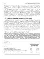
3.1 VARYING COMPOSITION OF EARTH’S SURFACE LAYER
The best place to start this discussion is at the bottom of things. All of us realize that there is a
major difference in stability as we walk along a sandy beach and then step onto a large rock
outcropping. Different soil conditions produce different amounts of firmness. Since rotating
machinery could potentially be placed anywhere on the planet, the soil conditions at that
location need to be examined to determine the stability of the ground. For new installations
or where foundations have shifted radically, it may be a good idea to have boring tests
conducted on soils where rotating machinery foundations will be installed. Table 3.1 shows
safe bearing load ranges of typical soils. The recommended maximum soil load from a
combination of both static and dynamic forces from the foundation and attached machinery
should not exceed 75% of the allowable soil bearing capacity as shown in Table 3.1.
3.2 HOW DO WE HOLD THIS EQUIPMENT IN PLACE?
I suppose someone has attempted to sit a motor and a pump on the ground, connected by the
shafts together with a coupling, and started the drive system up without bolting anything
down. My guess is that they quickly discovered that the machines started moving around a
little bit after start up, then began moving around a lot, and finally disengaged from each other
hopefully without sustaining any damage to either of the machines. Maybe they tried it again
and quite likely had the same results. I am sure they finally came to the conclusion that this
TABLE 3.1
Soil Composition
Bearing Capacities of Soils:
Safe Bearing Capacity
Type of Soil t/ft
2
MPa
Hard rock (e.g., granite, trap, etc.) 25–100 2.4–9.56
Shale and other medium rock (blasting for removal) 10–15 0.96–1.43
Hardpan, cemented sand and gravel, soft rock (difficult to chisel or pick) 5–10 0.48–0.96
Compact sand and gravel, hard clay (chiseling required for removal) 4–5 0.38–0.58
Loose medium and coarse sand medium clay (removal by shovel) 2–4 0.20–0.38
Fine loose sand 1–2 0.10–0.20
Piotrowski / Shaft Alignment Handbook, Third Edition DK4322_C003 Final Proof page 90 29.9.2006 5:53pm
90 Shaft Alignment Handbook, Third Edition
was not going to work for long periods of time and decided to ‘‘hold the machines’’ in their
starting position somehow. How are we going to do this exactly? What should we attach them
to? How about some wood? No, better yet, something like metal or rock, something that is
strong.
Our rotating equipment needs to be attached to something that will hopefully hold it in a
stable position for long periods of time. I have seen just about every possible configuration
you can imagine. Even the scenario mentioned above. The most successful installations
require that the machinery be attached to a stable platform that enables us to detach one
or more of the machines from its platform in the event that we want to work on it at another
location. Classically we attach and detach our equipment with threaded joints (i.e., bolts and
nuts). You could, I suppose, glue or weld the machines to their platform, and it would just be
a little more difficult to detach them later on.
The devices that we have successfully attached our machinery to are baseplates, soleplates,
or frames. There are advantages and disadvantages to each choice. The baseplates, sole-
plates, or frames are then attached to a larger structure, like a building, ship, aircraft and
automotive chassis, or Earth. There are many inventive ways of attaching rotating machinery
to transportation mechanisms (e.g., boats, motorcycles, airplanes), and design engineers are
still coming up with better solutions for these types of machinery-to-structure interface
systems. Our discussion here will concentrate on industrial machinery.
The vast majority of rotating machinery is either held in position by a rigid foundation
(monolithic), attached to a concrete floor, installed on an inertia block, or held in position on
a frame. There are advantages and disadvantages to each design. There are also good ways
and poor ways to design and install each of these methods to keep our machinery aligned and
prevent them from bouncing all over the place when they are running. In summary, machines
are attached to intermediary supports (i.e., baseplates, soleplates, and frames) that are then
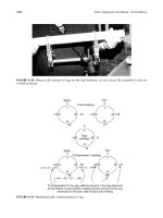
attached to structures (i.e., buildings, floors, foundations). Figure 3.1 shows a typical rigid
FIGURE 3.1 Rigid foundation for induced draft fan.
Piotrowski / Shaft Alignment Handbook, Third Edition DK4322_C003 Final Proof page 91 29.9.2006 5:53pm
Foundations, Baseplates, Installation, and Piping Strain 91
foundation design, Figure 3.2 shows a typica inertial block (aka floating) design, and
Figure 3.3 shows a typical frame design.
3.2.1 BASEPLATES
Baseplates are typically either cast or fabricated as shown in Figure 3.4 and Figure 3.5.
A fabricated baseplate is made using structural steel such as I-beams, channel iron, angle,
structural tubing, or plate, cutting it into sections, and then welding the sections together. It is
not uncommon to replace structural steel with solid plate to increase the stiffness of the base
similar to Figure 3.6.
3.2.1.1 Advantages
1. Most commonly used design for industrial rotating machinery
2. Provides excellent attachment to concrete foundations and inertia blocks assuming the
anchor bolts were installed properly and that the grout provides good bonding
3. Can be flipped upside down and grout poured into the cavity before final installation
FIGURE 3.2 Spring isolated inertia block with motor and pump.
FIGURE 3.3 Frame supporting a belt drive fan.
Piotrowski / Shaft Alignment Handbook, Third Edition DK4322_C003 Final Proof page 92 29.9.2006 5:53pm
92 Shaft Alignment Handbook, Third Edition
FIGURE 3.4 Cast baseplate.
FIGURE 3.5 Fabricated baseplate.
FIGURE 3.6 Weak structural steel was replaced with solid plate on this baseplate.
Piotrowski / Shaft Alignment Handbook, Third Edition DK4322_C003 Final Proof page 93 29.9.2006 5:53pm
Foundations, Baseplates, Installation, and Piping Strain 93
4. Machinery can be placed onto the baseplate prior to installation and roughly aligned in
the lateral and axial directions to insure that the foot bolt locations are drilled and
tapped accurately to hopefully prevent a bolt bound condition or incorrect shaft end to
shaft end spacing
5. Equipment mounting surfaces can be machined flat, parallel, and coplanar prior to
installation
6. Some designs include permanent or removable jackscrews for positioning the machinery
in the lateral and axial directions
3.2.1.2 Disadvantages
1. Usually more expensive than using soleplates or frames
2. Equipment mounting surfaces are frequently found not to be flat, parallel, and coplanar
prior to installation
3. Difficult to pour grout so it bonds to at least 80% of the underside of the baseplate
4. Possibility of thermally distorting baseplate using epoxy grouts if pour is thicker
than 4 in.
5. Frequently installed with no grout
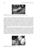
3.2.2 SOLEPLATES
Soleplates are effective machinery-mounting surfaces that are not physically connected
together. Figure 3.7 shows a soleplate being prepared for grouting on a medium-sized fan
housing. They are typically fabricated from carbon steel and there are usually two or more
soleplates required per concrete foundation or inertia block. Correct installation is more
FIGURE 3.7 Soleplate being prepared for grouting.
Piotrowski / Shaft Alignment Handbook, Third Edition DK4322_C003 Final Proof page 94 29.9.2006 5:53pm
94 Shaft Alignment Handbook, Third Edition