Handbook of Shaft Alignment Part 7 doc
Bạn đang xem bản rút gọn của tài liệu. Xem và tải ngay bản đầy đủ của tài liệu tại đây (2.05 MB, 50 trang )
FIGURE 6.58 Observe the amount of sag on the dial indicator as you rotate the assembly to the six
o’clock position.
T
B
0
T
B
0
Motor
Fan
Ϫ64
Ϫ48
+16 +55
+77
+22
Field readings
T
B
0
“Sag”
readings
T
B
E
E
EE
W
W
W
EWW
0
T
B
0
Motor
Fan
Ϫ58
Ϫ36
+22 +61
+89
+28
“Compensated” readings
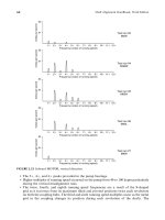
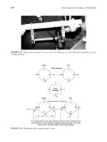
To compensate for the sag, add the amount of the sag observed
at the bottom to each bottom reading and the amount of the sag
observed on the each side to each side readin
g
Ϫ6
Ϫ12
Ϫ6
(Ϫ48 + 12 = Ϫ36)
(+16 + 6 = +22)
(
Ϫ64 + 6 = Ϫ58)
FIGURE 6.59 Mathematically compensating for sag.
Piotrowski / Shaft Alignment Handbook, Third Edition DK4322_C006 Final Proof page 270 26.9.2006 8:51pm
270 Shaft Alignment Handbook, Third Edition
that the centerline of rotation of the spindle and chuck is perfectly in line with the centerline of
rotation of the live center.
6.14 ZERO SAG BRACKETS
Is it possible to defy gravity and construct a cantilevered beam that compensates for
the elastic bending due to the force of gravity? You bet, within limits. Figure 6.63 shows a
bracket design where a second span bar holds a weight so that its position is on the opposite
side of the clamping point on the shaft, thereby counterbalancing the overhung weight. Figure
6.64 shows another arrangement for long spans where a different type of counterweight is
placed on a coupling spool that ‘‘lifts’’ the span bar. Neither of these prototype ‘‘anti-sag’’
devices are included in any of the dial indicator based alignment measurement systems.
Another long span bracket system fabricated from lightweight carbon tubes is shown in
Figure 6.65.
T
B
EW
0
T
B
EW
0
Motor
Fan
Field readings
−6
−12
−6−6
−12
−6
When the motor and fan shafts are perfectly aligned,
you should have these field readings
FIGURE 6.60 Ideal ‘‘shoot-for’’ readings (assuming no OL2R movement occurs).
FIGURE 6.61 Xmas tree bracket.
Piotrowski / Shaft Alignment Handbook, Third Edition DK4322_C006 Final Proof page 271 26.9.2006 8:51pm
Shaft Alignment Measuring Tools 271
6.15 DIAL INDICATOR SHAFT ALIGNMENT SYSTEM
MANUFACTURERS
The ensuing pages cover the currently available dial indicator based shaft alignment systems.
There are currently 7 manufacturers offering 19 different models.
A talented person could fabricate his own shaft alignment fixtures, purchase dial
indicators, and perform very satisfactory shaft alignment. The Xmas tree brackets shown
in this chapter were custom fabricated and work very well. Small to medium size
fixtures can be made that clamp around the outside of a shaft or coupling hub using roller
chain or hose clamps. The bracket body can be machined out of a block of steel or
fabricated with pieces of angle iron. Span bars can be made with tubing or round stock
and can be cut to various lengths to suit the users needs. Dial indicator sleeves can be
purchased to clamp on various diameters but the ones typically used clamp on 1=4, 5= 16,
or 3=8 in. rods with metric sizes available also. It may take several hours for some experiments
(also known as prototypes) to get what you need. On the other hand, the following tools have
already gone through a development cycle and are commercially available at relatively
modest prices.
Xmas tree bracket (bolt
to plate steel)
Plate steel
Angle iron
gusset support
Weld
Sch. 80 pipe (support on roller stands)
Weld
Post
0
50
10
40
20
30
+
_
10
40
20
30
0
50
10
40
20
30
+
_
10
40
20
30
FIGURE 6.62 How to measure sag when using an Xmas tree bracket.
Counterweight
FIGURE 6.63 Turvac Inc. sag compensation bracket design.
Piotrowski / Shaft Alignment Handbook, Third Edition DK4322_C006 Final Proof page 272 26.9.2006 8:51pm
272 Shaft Alignment Handbook, Third Edition
6.15.1 ACCUSHIM SYSTEMS
Accushim offers five different dial indicator based systems as shown in Figure 6.66 through
Figure 6.70. The REACT SA-2 system includes a pocket computer with alignment software.
Chain, brackets, posts, targets, and rods can be purchased separately to extend the capabil-
ities of the systems.
SK-1 system cost: $425.00
SK-2 system cost: $575.00
REACT HA-3 system cost: $825.00
REACT HA-2 system cost: $1500.00
FIGURE 6.64 Sag compensation fixture design. (Courtesy of Murray & Garig Tool Works, Baytown,
TX. With permission.)
FIGURE 6.65 Long span carbon tube. (Courtesy of Murray & Garig Tool Works, Baytown, TX. With
permission.)
Piotrowski / Shaft Alignment Handbook, Third Edition DK4322_C006 Final Proof page 273 26.9.2006 8:51pm
Shaft Alignment Measuring Tools 273
REACT SA-2 system cost: $2250.00
Manufacturers Web site: http:== www.accushim.com=
6.15.2 A-LINE SYSTEMS
A-Line Mfg. Inc. A-750 system as shown in Figure 6.71 is designed for smaller, hard to fit
equipment, and ANSI pumps. The A-1000 system is designed to clamp directly onto the
shafts and reach over the coupling as shown in Figure 6.72. The A-2000 model is designed to
clamp onto the coupling hub and reach over the hub flange as shown in Figure 6.73. The
A-3000 system combines both the A-1000 and A-2000 components (Figure 6.74). An optional
Palm OS computer is available with alignment software.
A-750 system cost: $875.00
A-1000 system cost: $1025.00
A-2000 system cost: $1225.00
A-3000 system cost: $1675.00
Palm OS with software cost: $750.00
Manufacturers Web site: http:== www.alinemfg.com=
FIGURE 6.66 SK-1 system. (Courtesy of Accushim Inc., Lyons, IL. With permission.)
FIGURE 6.67 SK-2 system. (Courtesy of Accushim Inc., Lyons, IL. With permission.)
Piotrowski / Shaft Alignment Handbook, Third Edition DK4322_C006 Final Proof page 274 26.9.2006 8:51pm
274 Shaft Alignment Handbook, Third Edition
FIGURE 6.68 REACT HA-3 system. (Courtesy of Accushim Inc., Lyons, IL. With permission.)
FIGURE 6.69 REACT HA-2 system. (Courtesy of Accushim Inc., Lyons, IL. With permission.)
FIGURE 6.70 REACT SA-2 system. (Courtesy of Accushim Inc., Lyons, IL. With permission.)
Piotrowski / Shaft Alignment Handbook, Third Edition DK4322_C006 Final Proof page 275 26.9.2006 8:51pm
Shaft Alignment Measuring Tools 275
6.15.3 BENCHMARK SYSTEM
The Benchmark PAS-1 alignment kit is shown in Figure 6.75 and Figure 6.76.
PAS-1 System cost: $1200.00
Manufacturers Web site: http:== www.withinspec.com=
6.15.4 MURRAY &GARIG SYSTEM
If you have not been noticing, there are several references in this book to describe the owner
of this company, Malcolm Murray. Malcolm is one of the foremost experts in shaft alignment
and holds seven patents, including a patent for several reverse indicator brackets as well as
FIGURE 6.71 A-750 system. (Courtesy of A-Line Mfg. Inc., Liberty Hill, TX. With permission.)
FIGURE 6.72 A-1000 system. (Courtesy of A-Line Mfg. Inc., Liberty Hill, TX. With permission.)
Piotrowski / Shaft Alignment Handbook, Third Edition DK4322_C006 Final Proof page 276 26.9.2006 8:51pm
276 Shaft Alignment Handbook, Third Edition
many other machinery alignment products shown in this book. He has been a consultant to
many of the manufacturers and users of dial indicator and laser-based shaft alignment
measurement systems shown in this book. The Murray & Garig K-5 shaft alignment system
is shown in Figure 6.77 and Figure 6.78.
K-5 system cost: $2300.00 to $2900.00 depending on options.
6.15.5 PETERSON ALIGNMENT TOOLS CO.SYSTEMS
Peterson Alignment Tools Co. offers two different alignment kits, the 20RA and 30RA, as
shown in Figure 6.79 and Figure 6.80. Also offered is the Alignment Managery 2002
FIGURE 6.73 A-2000 system. (Courtesy of A-Line Mfg. Inc., Liberty Hill, TX. With permission.)
FIGURE 6.74 A-3000 system. (Courtesy of A-Line Mfg. Inc., Liberty Hill, TX. With permission.)
Piotrowski / Shaft Alignment Handbook, Third Edition DK4322_C006 Final Proof page 277 26.9.2006 8:51pm
Shaft Alignment Measuring Tools 277
software program that operates on Windowsy operating systems that can be purchased
separately. Another version (Alignment Manager 3.1a) can be loaded onto a TI-86 scientific
calculator.
20RA system cost: $795.00 (includes Alignment Manager 2002 software program)
30RA system cost: $995.00 (includes Alignment Manager 2002 software program)
AMTI-86 scientific calculator cost: $199.00
Alignment Manager 2002 or 3.1a cost: $79.95
Manufacturers Web site: http:== www.petersontools.com=
FIGURE 6.75 PAS-1 system set up for reverse indicator method. (Courtesy of Benchmark Maintenance
Services Inc., Toronto, Ontario, Canada. With permission.)
FIGURE 6.76 PAS-1 system set up for face–rim method. (Courtesy of Benchmark Maintenance Services
Inc., Toronto, Ontario, Canada. With permission.)
Piotrowski / Shaft Alignment Handbook, Third Edition DK4322_C006 Final Proof page 278 26.9.2006 8:51pm
278 Shaft Alignment Handbook, Third Edition
6.15.6 TURVAC INC.SYSTEMS
Turvac Inc. offers five different systems. Figure 6.81 shows the miniature bracket that is used
for small couplings. Figure 6.82 shows the standard bracket kit. Figure 6.83 is the Journey-
man system which includes two standard bracket kits, a magnetic base, and the Shaft
Alignment Software Program or Technical reference library (the book Basic Shaft Alignment
FIGURE 6.77 K-5 system. (Courtesy of Murray & Garig Tool Works, Baytown, TX. With permission.)
FIGURE 6.78 K-5 system components. (Courtesy of Murray & Garig Tool Works, Baytown, TX. With
permission.)
Piotrowski / Shaft Alignment Handbook, Third Edition DK4322_C006 Final Proof page 279 26.9.2006 8:51pm
Shaft Alignment Measuring Tools 279
FIGURE 6.79 Peterson 20RA system. (Courtesy of Peterson Alignment Tools Co., Channahon, IL.
With permission.)
FIGURE 6.80 Peterson 30RA system. (Courtesy of Peterson Alignment Tools Co., Channahon, IL.)
Piotrowski / Shaft Alignment Handbook, Third Edition DK4322_C006 Final Proof page 280 26.9.2006 8:51pm
280 Shaft Alignment Handbook, Third Edition
Workbook and a manual for the Shaft Alignment Software Program). The software program
comes in two versions, one that runs on Windows or disk operating system (DOS)-based
computers, and another that runs on Apple Macintosh operating systems. The Journeyman
system can be bundled with a Windows (Master system) or Macintosh computer (Profes-
sional system) (Figure 6.84).
Miniature bracket cost: $495.00
Standard system cost: $1495.00
FIGURE 6.81 Miniature bracket. (Courtesy of Turvac Inc.)
FIGURE 6.82 Standard alignment system. (Courtesy of Turvac Inc.)
Piotrowski / Shaft Alignment Handbook, Third Edition DK4322_C006 Final Proof page 281 26.9.2006 8:51pm
Shaft Alignment Measuring Tools 281
Journeyman system cost: $3495.00
Master system cost: $5995.00
Professional system cost: $5995.00
Shaft Alignment Software Program and technical reference library cost: $1295.00
Manufacturers Web site: http:== www.turvac.com
6.15.7 UPDATE INTERNATIONAL SYSTEM
The Update Proaction system is shown in Figure 6.85.
Proaction system cost: $2490.00
Manufacturers Web site: http:== www.update-intl.com
6.16 DIAL INDICATOR MANUFACTURERS HARDWARE SPECIFICATIONS
A questionnaire was sent out to all of the above manufacturers concerning the pricing,
specifications, and features of their systems. The questions are listed below. A summary of
their answers is shown in Figure 6.86 and Figure 6.87.
FIGURE 6.83 Journeyman alignment system. (Courtesy of Turvac Inc.)
FIGURE 6.84 Master or Professional alignment system. (Courtesy of Turvac Inc.)
Piotrowski / Shaft Alignment Handbook, Third Edition DK4322_C006 Final Proof page 282 26.9.2006 8:51pm
282 Shaft Alignment Handbook, Third Edition
Dial indicator shaft alignment system questionnaire:
1. Are you a manufacturer of a dial indicator shaft alignment system?
_____ Yes
_____ No
2. Are you a distributor of a dial indicator shaft alignment system? If so, please list the
manufacturer of the dial indicator shaft alignment system. Please indicate the company,
address, phone number, contact person, and Web site (if applicable) of the manufacturer.
If you are a distributor only, skip the remaining questions.
Distributor for:
Model# _____
Manufacturer name _____
Address _____
P.O. Box
.
Suite _____
City _____
State=Province _____
Zip=Postal Code _____
Country _____
Phone# _____
Fax# _____
E-mail address _____
Web site _____
Questions for the manufacturer of a dial indicator shaft alignment system
1. What are the minimum and maximum shaft diameters that your alignment brackets can be
clamped to? If you have different models that can be clamped to different ranges of shaft
diameters, please indicate what range applies to each model.
_____ (inches? millimeters?) minimum shaft diameter
_____ (inches? millimeters?) maximum shaft diameter
2. What are the minimum and maximum distances your alignment brackets can span from
shaft to shaft (or from bracket to bracket)?
_____ (inches? millimeters?) minimum shaft-to-shaft span
_____ (inches? millimeters?) maximum shaft-to-shaft span
FIGURE 6.85 Update Proaction system. (Courtesy of Update International Inc., Denver, CO. With
permission.)
Piotrowski / Shaft Alignment Handbook, Third Edition DK4322_C006 Final Proof page 283 26.9.2006 8:51pm
Shaft Alignment Measuring Tools 283
Manufacturer system
=model
Accushim
SK-1
Accushim
SK-2
Accushim
REACT HA-3
Accushim
REACT HA-2
Accushim
REACT SA-2
A-Line
A-750
A-Line
A-1000
A-Line
A-2000
A-Line
A-3000
System price (US$)
425.00 575.00 825.00 1500.00
2250.00 875.00 1025.00 1225.00
1675.00
Basic system information
System weight (lb)
10
12
15
32
32
7
17
20
30
Brackets supplied?
One Two Two
Two
Two
Yes Yes Yes Yes
Dial indicators supplied?
One One Two
Two
Two
Yes Yes Yes Yes
Use on horizontally mounted machines? Yes
Yes Yes
Yes
Yes
Yes Yes Yes Yes
Use on vertically mounted machines?
Yes Yes Yes
Yes
Yes
Yes Yes Yes Yes
Custom calculator supplied?
No No No
No
Yes
Optional Optional Optional Optional
Standard computer supplied?
No No No
No
No
No
No
No
No
Alignment software included?
No No No
No
Yes
Optional Optional Optional Optional
Warranty period (months)
36
36
36
36
36
12
12
12
12
Purchase parts separately?
Yes Yes Yes
Yes
Yes
Shaft bracket fixtures
Minimum shaft diameter (in.)
0.375 0.375 0.375
0.375
0.375 0.5
1
3
1
Maximum shaft diameter (in.)
3.5 3.5 5
9.5
9.5
2.88 5
10.5 10.5
Minimum shaft-to-shaft span (in.)
2
2
2
3
3
1.5
1.5
1.5
1.5
Maximum shaft-to-shaft span (in.)
6
6
12
14
14
9
18
18
18
Minimum span bar height (in.)
3
3
3
3
3
2.2
3.5
2.75 3.2
Maximum span bar height (in.)
7
7
9
12
12
2.2
3.5
75
3.2
Brackets attach around shaft circumference?
Yes Yes Yes
Yes
Yes
Yes Yes Yes Yes
Brackets attach to face of coupling?
No No Yes
Yes
Yes
No
No
No
No
Shafts must be rotated together?
No No Yes
Yes
Yes
Yes Yes Yes Yes
How are rotational positions measured? Level
Level Level
Level
Level Twin spirit
level
Twin spirit
level
Twin spirit
level
Twin spirit
level
Shaft alignment method capabilities
Face–rim method?
Yes Yes Yes
Yes
Yes
Yes Yes Yes Yes
Reverse indicator method?
No No No
Yes
Yes
Yes Yes Yes Yes
Shaft to coupling spool method?
Yes Yes Yes
Yes
Yes
Yes Yes Yes Yes
Double radial method?
Yes Yes Yes
Yes
Yes
No
No
No
No
Face–face method?
Yes Yes Yes
Yes
Yes
Yes Yes Yes Yes
FIGURE 6.86
Dial indicator manufacturer pricing, specifications, and features
summary.
Piotrowski / Shaft Alignment Handbook, Third Edition DK4322_C006 Final Proof page 284 26.9.2006 8:51pm
284 Shaft Alignment Handbook, Third Edition
Manufacturer system
=model
Benchmark
PAS-1
Murray & Garig
K-5
Peterson
20RA
Peterson
30RA
Turvac Inc.
Miniature
Turvac Inc.
Standard
Turvac Inc.
Journeyman
Turvan Inc.
Master
Turvac Inc.
Professional
Update Int’l.
Proaction
System price (US$)
1200.00 2300.00–$2900.00 795.00 995.00
495.00 1495.00 3495.00 5995.00
5995.00 2490.00
Basic system information
System weight (lb)
5
24
9 12 2
8
20
25
25
35
Brackets supplied?
Yes Yes
Yes Yes Yes Yes
Yes
Yes
Yes
Yes
Dial indicators supplied?
Yes Yes
Yes Yes One Yes
Yes
Yes
Yes
Yes
Use on horizontally mounted machines?
Yes Yes
Yes Yes Yes Yes
Yes
Yes
Yes
Yes
Use on vertically mounted machines?
Yes Yes
Yes Yes Yes Yes
Yes
Yes
Yes
Yes
Custom calculator supplied?
Optional No
Optional Optional No
No
No
No
No
Yes
Standard computer supplied?
No
No
No No No
No
No
DOS-based
laptop Apple
Macintosh No
Alignment software included?
Optional No
Optional Optional No
No
Yes
Yes
Yes
Yes
Warranty period (months)
12
12
12 12 12
12
12
12
12
12
Purchase parts separately?
Yes Yes
Yes Yes Yes Yes
Yes
Yes
Yes
Shaft bracket fixtures
Minimum shaft diameter (in.)
0.5
1.5
0.75 0.75 0.13 0.5
0.5
0.5
0.5
0.625
Maximum shaft diameter (in.)
8
48
3.5 7.5 2.75 48
48
48
48
12
Minimum shaft-to-shaft span (in.)
4
1.25
5 5 0.5
0.5
0.5
0.5
0.5
2.5
Maximum shaft-to-shaft span (in.)
10
23
9 15 3
33
33
33
33
23
Minimum span bar height (in.)
3.5
1.75
2.1 1.9 0.5
À0.5
À0.5
À0.5
À0.5 3
Maximum span bar height (in.)
6.25 7
2.1 4.8 2.75 11
11
11
11
12
Brackets attach around shaft circumference? Yes
Yes
Yes Yes Yes Yes
Yes
Yes
Yes
Yes
Brackets attach to face of coupling?
No
No
Yes Yes No
Yes Yes
Yes
Yes
No
Shafts must be rotated together?
No
No
Yes Yes No
No
No
No
No
Yes
How are rotational positions measured?
Twin spirit
level
Automatic
protractor
Eyeball Eyeball Twin spirit
level
Twin spirit
level
Twin spirit
level
Twin spirit
level
Twin spirit
level
Spiral level
Shaft alignment method capabilities
Face–rim method?
Yes Yes
Yes Yes No
Yes Yes
Yes
Yes
Yes (addtn’l
parts req’d)
Reverse indicator method?
Yes Yes
Yes Yes Yes Yes
Yes
Yes
Yes
Yes
Shaft to coupling spool method?
Yes Yes
No No Yes Yes
Yes
Yes
Yes
Yes (addtn’l
parts req’d)
Double radial method?
Yes Yes
No No Yes Yes
Yes
Yes
Yes
Yes (addtn’l
parts req’d)
Face–face Method?
Yes Yes
No No No
Yes Yes
Yes
Yes
Yes (addtn’l
parts req’d)
FIGURE 6.87
Dial indicator manufacturer pricing, specifications, and features
summary.
Piotrowski / Shaft Alignment Handbook, Third Edition DK4322_C006 Final Proof page 285 26.9.2006 8:51pm
Shaft Alignment Measuring Tools 285
3. What is the distance from the point where the bracket touches the shaft to the center of
the span bar? If your bracket system can change the height of the span bar, what is the
minimum and maximum distance from the point where the bracket is touching the shaft
to the center of the span bar?
_____ (inches? millimeters?) fixed height
_____ (inches? millimeters?) minimum height
_____ (inches? millimeters?) maximum height
4. Can your brackets be attached to the face of coupling hubs rather than clamp around a
shaft diameter?
_____ Yes
_____ No
5. Can your alignment bracket system be used to perform the reverse indicator technique?
_____ Yes
_____ No
6. Can your alignment bracket system be used to perform the face-peripheral (i.e., face–rim)
technique?
_____ Yes
_____ No
7. Can your alignment bracket system be used to perform the shaft to coupling spool
technique?
_____ Yes
_____ No
8. Can your alignment bracket system be used to perform the double radial technique?
_____ Yes
_____ No
9. Can your alignment bracket system be used to perform the face–face technique?
_____ Yes
_____ No
10. Do the shafts have to be rotated together while capturing readings? If so, what amount of
rotational backlash between the two shafts can be tolerated before measurement accuracy
is sacrificed?
_____ Yes
_____ No
_____ (angular degrees) allowable backlash
11. Do you supply dial indicators with your system? If so, are they standard types of dial
indicators that can be purchased directly from the dial indicator manufacturers (e.g.,
Starrett, Mitutoyo, Central, etc.) in the event that the user breaks or loses a dial
indicator?
_____ Yes, indicators are supplied
_____ No, indicators not supplied
Manufacturer and model _____
12. Can other measuring devices such as LVDTs, proximity probes, lasers, or CCDs be used
with or on your brackets?
_____ Yes
_____ No
13. How do you measure the rotational position of the brackets, indicators, and sensors when
capturing readings?
Angle measuring device used _____
Piotrowski / Shaft Alignment Handbook, Third Edition DK4322_C006 Final Proof page 286 26.9.2006 8:51pm
286 Shaft Alignment Handbook, Third Edition
14. If a user damages or loses a component of the system, can the parts be purchased
separately?
_____ Yes
_____ No
15. Can the system be used on vertically oriented rotating machinery?
_____ Yes
_____ No
16. Can the system be configured to measure English or metric units?
_____ Yes
_____ No
17. If your system is patented, please send a copy of the patent (in English). If you have
patents in other countries, please indicate where the patents are held and their corre-
sponding patent number or identification.
_____
_____
_____
18. What is your warranty period?
_____ (days, months, years)
19. What are the recommended calibration intervals? Does the unit have to be sent back to
the factory for calibration, and what is the charge for recalibration? Is the calibration you
offer traceable back to U.S. or International Standards?
_____ (days, months, years) recommended calibration interval
Send back to factory?
_____ Yes
_____ No
Traceable to standards?
_____ Yes
_____ No
20. Do you offer equipment for the user to check and adjust calibration? If so, what is the
cost of the test equipment?
_____ Yes
_____ No
21. If you have introduced new shaft alignment system models, do the people who own your
original models have the option to trade in their older models to upgrade to a newer
model? If so, what is the cost of the upgrade?
_____ Yes—upgrade cost _____ (US$)
_____ No
22. What is the overall weight of the entire system?
_____ (pounds, kilograms) system weight
23. What is the price (or price range) of the system?
_____ (US$)
This chapter has shown the wide variety of measurement tools that are used in aligning
rotating machinery. Chapter 10 through Chapter 15 will show how these tools are used to
capture shaft-to-shaft positional measurements.
Piotrowski / Shaft Alignment Handbook, Third Edition DK4322_C006 Final Proof page 287 26.9.2006 8:51pm
Shaft Alignment Measuring Tools 287
BIBLIOGRAPHY
A Primer on Displacement Measuring Interferometers, Zygo Corporation, Middlefield, CT.
Beckwith, T.G., Buck, N.L., Mechanical Measurements, Addison-Wesley, Reading, MA, 1969, LCC#
70-85380.
Beynon, J.D., Lamb, D.R., Charge Couple Devices and Their Applications, McGraw-Hill, New York,
1980, ISBN# 0-07-084522-0.
Blubaugh, R.L., Watts, H.J., Aligning rotating equipment, Chemical Engineering Progress, 65 (4), 1969,
44–46.
Boiler and Machinery Engineering Report—Shaft Alignment for Rotating Machinery, Section 4.0, # 4.26,
October 1989, American Insurance Services Group, Inc., New York, NY.
Brook, K., Personal Correspondence for Partial Arc Mathematics, June 1994.
Brotherton, M., Masers and Lasers, McGraw-Hill, New York, 1964, LCCCN 63-23249.
Carman, D.B., Determining Small Planar Rotations of Cylinders Using Computer Vision, Doctoral
thesis, 1988.
Carman, D.B., Measurement of Shaft Alignment Using Computer Vision, Doctoral thesis, 1989.
66 Centuries of Measurement, Sheffield Corporation, Sheffield, 1987, LCCC# 530.81.
Dodd, V.R., Total Alignment, The Petroleum Publishing Co., Tulsa, Okla, 1975.
Doeblin, E., Measurement Systems: Application and Design, McGraw-Hill, New York, 1975, ISBN#
0-07-017336-2.
Dreymala, J., Factors Affecting and Procedures of Shaft Alignment, Technical and Vocational Depart-
ment, Lee College, Baytown, TX, 1970.
Durkin, T., Aligning shafts. Part I—Measuring misalignment, Plant Engineering, January 11, 1979.
Evans, G., Casanova, P., Azcarate, A.M., The Optalign Training Book, Ludeca Inc., Miami, FL, 1990,
Catalog# 01-705-01.
Franklin, D.E., Active Alignment, Presented at the 10th Biennial Machinery Dynamics Seminar, The
National Research Council, Canada, September 1988.
Hecht, J., The Laser Guidebook, McGraw-Hill, 1992, ISBN# 0-07-027737-0.
Heid, J., Photography Without Film, MacWorld, Boone, ‘‘IA’’, September 1994, pp. 140–147.
Horton, H.L., Mathematics at Work, 3rd ed., Industrial Press Inc., New York, NY, 1990, ISBN#
0-8311-3029-6.
King, W.F., Peterman, J.E., Align Shafts, Not Couplings! Allis Chalmers Electrical Review, 2nd Quarter,
1951, pp. 26–29.
Laser Diode User’s Manual, Ref. No. HT519D, Sharp Electronics Corporation, 22–22, Nagaike-Cho,
Abeno-Ku, Osaka, 545, Japan.
Malak, S.P., Solomon, D.W., An Analysis of Non-Rotated 3-Dimensional Shaft Alignment Instrumenta-
tion Compared with Rotated 2-Dimensional Shaft Alignment Measurement Methods Obtained
Currently by Dial Indicator Techniques, SMI-LI-TR1.1, Lineax Instruments, SMI Spring
Mornne, Inc., August 1985.
Mims, F.M., III, Getting Started in Electronics, Tandy Corporation, 1993,Catalog# 276-5003.
Murray, M.G., Choosing an Alignment Measurement Setup, Murray and Garig Tool Works, Baytown,
TX, Personal Correspondence, October 12, 1979.
Murray, M.G., Jr., Alignment System, U.S. Patent 4,367,594, U.S. Patent Office, Washington, D.C.,
January 11, 1983.
Murray, M.G., OPTALIGN—Laser–Optic Machinery Alignment System—Report Following Four
Month Test, Murray and Garig Tool Works, Baytown, TX, April 2, 1985.
Murray, M.G., Alignment Manual for Horizontal, Flexibly Coupled Rotating Machines, Murray and
Garig Tool Works, 3rd ed., Baytown, TX, April 21, 1987.
Nelson, C.A., Orderly steps simplify coupling alignment, Plant Engineering, June 1967, 176–178.
Optoelectronics Components Catalog, UDT Sensors Inc., Hawthorne, CA.
Piotrowski, J.D., Alignment Techniques, in: Proceedings Machinery Vibration Monitoring and Analysis
Meeting, New Orleans, LA, Vibration Institute, Clarendon Hills, IL, June 26–28, 1984.
Piotrowski, J.D., The graphical alignment calculator, in: Machinery Vibration Monitoring and Analysis,
Vibration Institute, Clarendon Hills, IL, 1980.
Piotrowski / Shaft Alignment Handbook, Third Edition DK4322_C006 Final Proof page 288 26.9.2006 8:51pm
288 Shaft Alignment Handbook, Third Edition
2003 Precision alignment and balancing guide, Maintenance Technology, 16 (11), 2003.
Samzelius, J.W., Check points for proper coupling alignment, Plant Engineering, June 1952, 92–95.
Schwartz, A., Calculus and Analytic Geometry, Holt, Rinehart, and Winston Inc., New York, 1967,
LCCC# 67-11748.
Techniques for Digitizing Rotary and Linear Motion—Encoder Division, 4th printing, Dynamics Re-
search Corporation, Wilmington, MA, 1992.
Teskey, W.F., Dynamic Alignment Project, University of Calgary, Calgary, Alberta, November 18, 1994.
Tools & Rules, Bulletin No. 1211, L.S. Starrett Co., Athol, MA.
Two Step Dial Indicator Method, Bulletin No. MT-SS-04-001, Rexnord, Thomas Flexible Coupling
Division, Warren, PA, 1979.
Yarbrough, C.T., Shaft alignment analysis prevents shaft and bearing failures, Westinghouse Engineer,
May 1966, 78–81.
Piotrowski / Shaft Alignment Handbook, Third Edition DK4322_C006 Final Proof page 289 26.9.2006 8:51pm
Shaft Alignment Measuring Tools 289
Piotrowski / Shaft Alignment Handbook, Third Edition DK4322_C006 Final Proof page 290 26.9.2006 8:51pm
7
Correcting Misalignment
Assuming that we are attempting to align healthy machines (good bearings, seals, shafts,
couplings, baseplates, foundations, etc.), our objectives are as follows:
Objective 1: Determine the relative position of two centerlines of rotation of the machinery shafts.
If the amount of misalignment is not acceptable decide which way and how far one, or the other,
or both of the machines have to move in the X, Y, and Z planes (i.e., up, down, left, right, toward
or away) to improve the desired off-line alignment.
Objective 2: Physically move one or the other or both of the machines in the X, Y, and Z planes
(i.e., up, down, left, right, toward or away) as shown in Figure 7.1. Go back to objective 1 until
you reach acceptable alignment tolerances.
7.1 INSTALLING MACHINERY FOR THE FIRST TIME
If we are installing new machinery for the very first time, there are several issues we need to
deal with. Whether the machinery will be placed on a rigid foundation, an inertia block, or a
structural steel frame, and the following items should be taken into consideration:
1. If we are installing machinery on a rigid foundation or an inertia block has the concrete
and grout been given enough time to cure? Typically concrete- and cement-based grouts
will have achieved 50% of their cure after 4–7 d and 80%–90% of their cure after 15–30 d.
Therefore it is not recommended to place machinery onto its baseplate the day after the
concrete was poured.
2. Will there be any external connections made to the machines such as piping, ductwork, or
electrical conduit? If so, have these external connections already been fabricated and put
in their final position before placing the machinery onto its baseplate? Hopefully not. The
machinery should be set into a rough or final alignment position before making any
connections. Remember, the piping flanges on pumps, compressors, and steam turbines
are fluid connection points, not piping anchors. Adequate support structures should be
provided to support the piping that will eliminate any stresses on the machinery itself.
3. Have any considerations been drilled and tapped into the baseplate or soleplates where
the machines will be mounted? If so, have the machines that will actually be mounted to
the base been at least roughly aligned in the axial and lateral directions on this base
before drilling and tapping the holes insuring that the foot bolts have been placed in the
center of the holes? Hopefully so. Drilling and tapping holes in the baseplate or soleplate
is more difficult than it looks and requires some effort in locating the holes precisely.
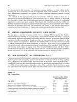
Figure 7.2 shows the specifications from the National Electrical Manufacturers Association
(NEMA) for foot pad sizes, the hole diameters to be drilled into the machinery feet, and the
bolt diameter to hold that foot firmly to the baseplate. As you can see, there is not much
Piotrowski / Shaft Alignment Handbook, Third Edition DK4322_C007 Final Proof page 291 26.9.2006 8:43pm
291
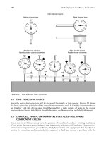
room between the shank of the bolt and the hole drilled into the machine foot. Figure 7.3
shows the bolt hole size, the bolt used for that hole size, and the total diametral clearance
between the bolt and the hole. Be aware that if the bolt is placed in the center of the hole the
machine can only translate half that amount (i.e., the radial clearance).
7.2 BOLT-BOUND CONDITIONS
Notice that in three of the footprint sizes there are only 78 mils of radial clearance (156
diametral clearance) on each side of the bolt assuming it is centered in the hole. There is not a
lot of room to move a machine sideways. In the vertical direction, if you wanted to move a
machine up 250 mils (i.e., 1=4 in.), you could indeed install a shim or plate to raise it that high.
But if you wanted to move a machine 250 mils sideways, you would become ‘‘bolt bound’’
before the total move was made. The restrictions between the holes drilled in the machinery
feet and the bolts holding the feet to the base are the primary reason why more machinery is
misaligned in the side-to-side and axial directions than in the vertical direction. In the up
direction, you have no limit to how far up it can go. You can add as many shims under the
machinery feet (within reason) as you want. However, in the side-to-side or end-to-end
direction, you will be limited by the amount of room left between the holes drilled in the
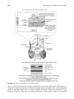
machinery feet and the bolts holding the feet to the base. If you do not know how much room
there is between the shank of the bolt and the hole in the machine case, loosen the bolt,
remove the washer, and thread the bolt in a few turns as shown in Figure 7.4.
Shaft alignment in a three-dimensional world
Axial position
Horizontal position
Vertical position
FIGURE 7.1 Moving in the X, Y, and Z planes.
Piotrowski / Shaft Alignment Handbook, Third Edition DK4322_C007 Final Proof page 292 26.9.2006 8:43pm
292 Shaft Alignment Handbook, Third Edition
4 in. ϫ 4 in. footprint
3.5 in. ϫ 3.5 in. footprint
13/16 in. hole diameter
5/8 in. bolt
188 mils total diametral clearance
3 in. ϫ 3 in. footprint
2.5 in. ϫ 2.5 in. footprint
2.5 in. ϫ 3 in. footprint
2 in. ϫ 2 in. footprint
2 in. ϫ 1.5 in. footprint
NEMA Motor frame—foot pad sizes
21/32 in. hole diameter
1/2 in. bolt
156 mils total diametral clearance
13/32 in. hole diameter
5/16 in. bolt
94 mils total diametral clearance
17/32 in. hole diameter
3/8 in. bolt
156 mils total diametral clearance
17/32 in. hole diameter
3/8 in. bolt
156 mils total diametral clearance
FIGURE 7.2 NEMA foot pad specifications.
Bolt Diameter Hole Hole diameter Clearance
5/16 in. 0.313 13/32 in. 0.406 0.094
3/8 in. 0.375 17/32 in. 0.531 0.156
1/2 in. 0.5 21/32 in. 0.656 0.156
5/8 in. 0.625 13/16 in. 0.813 0.188
FIGURE 7.3 Bolts, hole diameters, and diametral clearances.
Piotrowski / Shaft Alignment Handbook, Third Edition DK4322_C007 Final Proof page 293 26.9.2006 8:43pm
Correcting Misalignment 293
7.3 LAST RESORT MEASURES FOR BOLT-BOUND CONDITIONS
An undercut bolt has the shank of the bolt cut down to the diameter at the root of the threads
of the bolt as shown in Figure 7.5. Undercutting a bolt is one of the last resort measures you
would take to achieve alignment. Another last resort measure would be to enlarge or slot the
hole in the machine case.
Before you do this, study Chapter 8 and learn how to determine a lateral movement
envelope. This could save you a considerable amount of time and unnecessary pain aligning
machinery. In the event that you decide that undercutting a bolt is absolutely necessary, do
FIGURE 7.4 Observing bolt clearances at a machine foot.
Piotrowski / Shaft Alignment Handbook, Third Edition DK4322_C007 Final Proof page 294 26.9.2006 8:43pm
294 Shaft Alignment Handbook, Third Edition