Handbook of Shaft Alignment Part 10 pptx
Bạn đang xem bản rút gọn của tài liệu. Xem và tải ngay bản đầy đủ của tài liệu tại đây (576.76 KB, 50 trang )
features of the Shaft 100 system but also includes: alignment of offset mounted equipment
(Cardan=U-joint driven machinery), alignment of multiple element drive systems, can be used
for measuring as well as entering OL2R movement information, two magnetic bases, and a
system printer.
Shaft 30 system cost: $9995.00
Shaft 100 system cost: $15500.00
Shaft 200 system cost: not supplied
Manufacturer’s Web site: http:==www.fixturlaser.com=
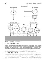
15.2.5 HAMAR SYSTEMS
The operating principle of the Hamar laser alignment systems is based on a single laser, dual
detector using a beam splitter as shown in Figure 15.4. A bracket is attached to each shaft.
The laser is attached to one of the brackets and the detector target to the other bracket. The
operator then positions the laser and detector assemblies to center the beam in the detector
target area.
The Model S-640 system is shown in Figure 15.12. The detector target output is connected
to a computer interface module (Model R-358) via a cable, which is then connected to a
laptop computer via the serial communications port. An alignment software program sup-
plied with the system is loaded into your laptop computer and the software prompts the user
through the alignment process.
The Model S-650 system is shown in Figure 15.13. The detector target output is transmitted
via infrared data transmission to a receiver–computer interface module (Model A-908), which
is connected to a laptop computer via the serial communications port. An alignment software
program and laptop computer are supplied with the system.
Model S-640 system cost: not supplied
Model S-650 system cost: not supplied
Manufacturer’s Web site: http:==www.hamarlaser.com=
FIGURE 15.11 Shaft 200 system. (Courtesy of FixturLaser, Molndal, Sweden. With permission.)
Piotrowski / Shaft Alignment Handbook, Third Edition DK4322_C015 Final Proof page 420 29.9.2006 6:55pm
420 Shaft Alignment Handbook, Third Edition
15.2.6 PRU
¨
FTECHNIK SYSTEMS
The first useable laser shaft alignment system was introduced by Pru
¨
ftechnik in 1984. The
operating principle of this system is shown in Figure 15.2 where a single laser, mounted on
one shaft, is aimed at a roof prism, mounted on the other shaft, which reflects the beam
directly back toward its point of origin but offsets the beam a specified distance so the laser
FIGURE 15.12 Model S-640. (Courtesy of Hamar Laser Instrument Co., Danbury, CT. With permission.)
FIGURE 15.13 Model S-650. (Courtesy of Hamar Laser Instrument Co., Danbury, CT. With permission.)
Piotrowski / Shaft Alignment Handbook, Third Edition DK4322_C015 Final Proof page 421 29.9.2006 6:55pm
Electronic and Electro-Optical Shaft Alignment Systems 421
can strike onto the surface of the photodetector target. After attaching the brackets to each
shaft, the operator installs the laser–detector head onto one of the brackets and the roof prism
onto the other bracket. Using the display and keypad, the operator enters information about
the drive system being aligned and once the laser beam starts operating, the operator adjusts
the position of the roof prism to center the returning laser beam onto the photodiode target.
The operator then proceeds through the instructions prompted via the display and keypad to
capture the shaft positions.
The first Optalign system incorporated an infrared laser (not visible to the naked eye) but as
visible lasers became available, they were incorporated into subsequent models.
The Pocketalign system is shown in Figure 15.14. This system utilizes a personal digital
assistant (PDA) for the operator and keypad. The PDA operating system requires Microsoft
Mobile 2003 and a CF II interface card is required. It uses the same laser–detector head as
the Smartalign system. The PDA can be purchased through the manufacturer or you can
buy your own. Communication cabling is provided to transfer files from the PDA to a
personal computer for file archiving. Continuous sweep measurement mode software can
be purchased separately.
The Optalign Plus system as shown in Figure 15.15, now in its fourth generation, has been
the workhorse of their product line. The operational software is imbedded into the laser–
detector sensor assembly, not the operator keypad and display. It is offered in two basic
configurations, the ‘‘Entry Level’’ model and the ‘‘All Features’’ model. This system is also
fully configurable with the exact features and functions the user desires, ‘‘a
`
la carte.’’
Intrinsically safe models are also available. The system comes with the laser–detector trans-
ducer, the prism, an operator keypad and display, a 6 ft (2 m) cable, brackets for clamping
onto shafts up to 8.5 in. in diameter, posts (200 and 600 mm) for attaching the laser–detector
and prism to the brackets, a computer cable and adapter, tape measure, manual, cleaning
cloth, protective covers, and a carrying case. Optional firmware can be purchased which can
FIGURE 15.14 Pocketalign system. (Courtesy of Pru
¨
ftechnik, Ismaning, Germany. With permission.)
Piotrowski / Shaft Alignment Handbook, Third Edition DK4322_C015 Final Proof page 422 29.9.2006 6:55pm
422 Shaft Alignment Handbook, Third Edition
save either 25 or 99 files, enter both vertical and horizontal target specifications and thermal
growth data, vertical shaft alignment, multipoint measurement mode, alignment of spacer
shafts, machinery with 6 ft, ‘‘static feet’’ function for bolt-bound or base-bound machines,
alignment tolerances, and extended measurement range (known as InfiniRange).
Optalign Plus Entry Level system cost: $6600.00
Optalign Plus Intrinsically Safe Entry Level system cost: $10575.00
Optalign Plus All Features system cost: $13500.00
Optalign Plus Intrinsically Safe All Features system cost: $16875.00
Manufacturer’s Web site: http:==www.pruftechnik.com=
The Smartalign system is shown in Figure 15.16. The laser–detector transducer visually
looks the same as the Optalign Plus where the operational software is actually imbedded in
the transducer. In the case of the Smartalign system, the operational software is actually
imbedded in the operator keypad and display. The system comes with: the laser–detector
transducer, the prism, an operator keypad–display, a 6 ft (2 m) cable, brackets for clamping
onto shaft up to 8.5 in. in diameter, 20 different posts of various lengths for attaching the
laser–detector and prism to the brackets, ‘‘smartREADER
1
’’ software, a computer cable and
adapter, tape measure, manual, cleaning cloth, protective covers, and a carrying case.
Smartalign system cost: $14800.00
The Rotalign Pro system is a more advanced system than the systems described above and
is shown in Figure 15.17. The system comes with an alignment computer, a laser sender,
a receiver, a 6 ft (2 m) cable, brackets for clamping onto shaft up to 8.5 in. in diameter,
FIGURE 15.15 Optalign Plus system. (Courtesy of Pru
¨
ftechnik, Ismaning, Germany. With permission.)
Piotrowski / Shaft Alignment Handbook, Third Edition DK4322_C015 Final Proof page 423 29.9.2006 6:55pm
Electronic and Electro-Optical Shaft Alignment Systems 423
20 different posts of various lengths for attaching the laser–detector and prism to the brackets,
beam adjustment tube, a computer cable and adapter, tape measure, manual, cleaning cloth,
protective covers, and a carrying case. The basic software of this multifunction device enables
one to align horizontally or vertically mounted machinery, coupled or uncoupled shafts,
alignment of multiple element drive systems, soft foot detection, target specifications and
thermal growth entry for all machines in the train, infrared data transmission to computer,
and U-joint (Cardan shaft) alignment. Additional software packages enables alignment of
machinery bores (Boralign) and straightness and flatness (Levalign) measurement.
Rotalign Pro system cost: $18900.00
Rotalign Pro Intrinsically Safe system cost: $23700.00
Boralign add-on package cost: $8500.00
Boralign Long Range upgrade package cost: $6969.00
15.2.7 SPM INSTRUMENT INC.SYSTEM
The LineLazer system is based on the reverse indicator method and uses a dual beam–dual
detector system (See Figure 15.19). The LineLazer is an accessory that interfaces with the
Leonova system, which is capable of doing vibration analysis and balancing with the appro-
priate add-on hardware.
A bracket is attached to each shaft and the laser–detector heads are then attached to each
bracket. The operator then aims the laser toward the detector targets on the opposing shaft
FIGURE 15.16 Smartalign system. (Courtesy of Pru
¨
ftechnik, Ismaning, Germany. With permission.)
Piotrowski / Shaft Alignment Handbook, Third Edition DK4322_C015 Final Proof page 424 29.9.2006 6:55pm
424 Shaft Alignment Handbook, Third Edition
and centers each beam. Inclinometers are incorporated into the heads to measure the angular
position of the shafts. A wireless transmission sends the detector signals to the operator
display. The operator then rotates the shafts to capture the shaft positions. Once the
measurement process has been completed, the user then obtains the corrective moves for
the machine selected as the movable machine.
LineLazer system cost: US$5500.00 (does not include the cost of the Leonova interface
system)
Manufacturer’s Web site: http:==www.spminstrument.com=
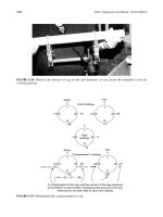
15.2.8 VIBRALIGN SYSTEM
The Shaft Hog system is shown in Figure 15.20 and is based on the reverse indicator method
and uses a dual beam–dual detector system. The system comes with: two laser–detector units,
cables, display box, shaft clamp brackets, mounting rods, measuring tape, manual (printed
and CD-ROM), and a pocket guide.
Shaft Hog system cost: US$4250.00
Manufacturer’s Web site: http:==www.vibralign.com=
FIGURE 15.17 Rotalign Pro system. (Courtesy of Pru
¨
ftechnik, Ismaning, Germany. With permission.)
Piotrowski / Shaft Alignment Handbook, Third Edition DK4322_C015 Final Proof page 425 29.9.2006 6:55pm
Electronic and Electro-Optical Shaft Alignment Systems 425
15.3 LASER SYSTEM MANUFACTURERS HARDWARE SPECIFICATIONS
A questionnaire was sent out to all of the above manufacturers concerning the pricing,
specifications, and features of their systems. The questions are listed below. A summary of
their answers is shown in Figure 15.21 through Figure 15.32.
Laser shaft alignment system questionnaire
1. Are you a manufacturer of a laser shaft alignment system?
____ Yes
____ No
2. Are you a distributor of a laser shaft alignment system? If so, please list the manufacturer
of the laser shaft alignment system. Please indicate the company, address, phone number,
contact person, and Web site (if applicable) of the manufacturer. If you are a distributor
only, skip the remaining questions.
Distributor for:
Model # ____________________________________________________________________
Manufacturer name __________________________________________________________
Address ____________________________________________________________________
P.O. Box
.
Suite _____________________________________________________________
City ________________________________________________________________________
State=Province _______________________________________________________________
FIGURE 15.18 Rotalign Ultra system. (Courtesy of Pru
¨
ftechnik, Ismaning, Germany. With permission.)
Piotrowski / Shaft Alignment Handbook, Third Edition DK4322_C015 Final Proof page 426 29.9.2006 6:55pm
426 Shaft Alignment Handbook, Third Edition
ZIP=Postal code _____________________________________________________________
Country ____________________________________________________________________
Phone # ____________________________________________________________________
Fax # ______________________________________________________________________
E-mail address _______________________________________________________________
Web site ____________________________________________________________________
Questions for the manufacturer of a laser shaft alignment system
3. Describe the basic operation of your laser measurement system. Use drawings or diagrams
to enhance your explanation if possible.
4. What is the overall weight of the entire system?
_____ (pounds, kilograms) system weight
5. What is the price (or price range) of the system in U.S. dollars?
_____ (U.S. dollars)
6. How is the unit powered?
_____ internal batteries
_____ AC power source
_____ batteries or AC power source
FIGURE 15.19 Leonova LineLazer system. (Courtesy of SPM Instruments, Marlborough, CT. With
permission.)
Piotrowski / Shaft Alignment Handbook, Third Edition DK4322_C015 Final Proof page 427 29.9.2006 6:55pm
Electronic and Electro-Optical Shaft Alignment Systems 427
7. If batteries are used, what sizes are required and how many are needed? Are the batteries
rechargeable?
Battery size and type _______________________________________________________
_____ Rechargeable
_____ Not rechargeable
8. What battery life can be expected for continuous use on battery power?
_____ (minutes, hours) expected battery life
9. Can the unit be plugged into AC electric supplies? Can it work on either 50 or 60 Hz
circuits and voltage ranges from 90 to 220 VAC?
_____ Yes
_____ No
10. What type of laser is used in your system and how does it work (beam frequency in nm,
continuous or pulse? Pulse duration, beam diameter at collimator exit, beam diameter at
1, 3, 10 m, power output, safety precautions, etc.)?
Type of laser _______________________________________________________________
Beam frequency _____________________________________________________________
_____ continuous
_____ pulse duration _________________________________________________________
_____ (inches, millimeters) beam diameter at exit
_____ (inches, millimeters) beam diameter at 1 m
_____ (inches, millimeters) beam diameter at 3 m
_____ (inches, millimeters) beam diameter at 10 m
_____ (milliwatts) power output
Safety precautions ___________________________________________________________
11. If you are using semiconductor junction diode lasers, which typically produce a low-
quality beam that is divergent, elliptical, and astigmatic, what optical correction is
incorporated in your system to correct these deficiencies?
___________________________________________________________________________
___________________________________________________________________________
___________________________________________________________________________
FIGURE 15.20 V180 system. (Courtesy of Vibralign, Richmond, VA. With permission.)
Piotrowski / Shaft Alignment Handbook, Third Edition DK4322_C015 Final Proof page 428 29.9.2006 6:55pm
428 Shaft Alignment Handbook, Third Edition
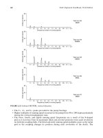
Question Number
Manufacturer
Damalini
Damalini
Damalini
System
=Model
D450
D505
D525
Manufacturer Web Site
www.damalini.com
www.damalini.com
www.damalini.com
5
System price (U.S. dollars)
4,995
11,500
Basic System Information
4
Total unit weight (lbs)
27 lbs (12 kg)
27 lbs (12 kg)
27 lbs (12 kg)
3
Alignment operating principle
Reverse indicator
Reverse indicator
Reverse indicator
21
Intrinsically safe
=explosion proof models? No
No
No
16
Shock protection
Internal shock protection
Internal shock protection
Internal shock protection
20
Operating temperature range
328F–122
8F3
28F–1228F3
2
8F–1228F
22
Environmental protection
FDA approved, 21 CFR 1040. 10&11,
SS-EN-60825-1-1994
FDA approved, 21 CFR 1040. 10&11,
SS-EN-60825-1-1994
FDA approved, 21 CFR 1040.
10&11, SS-EN-60825-1-1994
Laser Emitter
(Source
)
9
Laser type
Visible red diode
Visible red diode
Visible red diode
9
Number of lasers used
2
2
2
9
Wavelength
635–670 nm
635–670 nm
635–670 nm
9
Beam diameter at exit
3 mm
3 mm
3 mn
9
Max. beam power output
1 mW
1 mW
1 mW
9
Laser safety class
Class 2
Class 2
Class 2
Max. recommended distance
6
Laser power supplied by . . .
Cable from D279 display unit
Cable from D279 display unit
Cable from D279 display unit
Cable length
7 ft (2 m)
 1, 5, 10 m optional
7 ft (2 m)
 1, 5, 10 m optional
7 ft (2 m)
 1, 5, 10 m optional
Dimensions
WÂHÂ
D (inches)
Laser–Detector
(
Receiver)
12
Type
Single axis photodiode (two)
Single axis photodiode (two)
Single axis photodiode (two)
12
Detector measurement planes
1
1
1
12
Detector measurement area
10 mm  10 mm
10 mm
 10 mm
10 mm
 10 mm
12
Number of detectors used
2
2
2
12
Linearity
12
Accuracy
=resolution
1 mm1
mm1
mm
12
Optical filtering?
Grey filter
Grey filter
Grey filter
15
Beam position data transfer via . . .
Cable
Cable
Cable
Detector power supplied by . . .
D279 display unit
D279 display unit
D279 display unit
Battery life at full charge
24–48 h
24–48 h
24–48 h
Dimensions
WÂHÂD
(inches)
Interchangeable with other display units? No
No
No
FIGURE 15.21
Laser system hardware comparison chart.
Piotrowski / Shaft Alignment Handbook, Third Edition DK4322_C015 Final Proof page 429 29.9.2006 6:55pm
Electronic and Electro-Optical Shaft Alignment Systems 429
Question Number
Manufacturer
Damilini
Damilini
Damilini
System
=Model
D450
D505
D525
Manufacturer Web Site
www.damalini.com
www.damalini.com
www.damalini.com
Operator Interface
14
Alignment computer and software
included?
Yes
Yes
Yes
14
Dimensions W
ÂH
ÂD (inches)
Weight (with battery)
Display screen (type and size)
Software installation
Pre-installed
Pre-installed
Pre-installed
Battery type
=number requirements
4 C (R14) batteries
4 C (R14) batteries
4 C (R14) batteries
Battery life at full charge
24–48 h
24–48 h
24–48 h
6
Optional AC power and requirements 90–220
VAC=50–60 Hz
90–220 VAC
=50–60 Hz
90–220 VAC
=50–60 Hz
30
Enter off-line to running movement?
No
No
No
14
Interface system with standard computers? Yes, RS232
Yes, RS232
Yes, RS232 serial
Store alignment jobs?
18
Turned OFF by mistake?
Start over
Start over
Start over
Operational Info
25
Shafts must be rotated together?
No
No
No
26
How are rotational positions measured? Internal
inclinometer and external bubble Internal inclinometer
and external bubble Internal inclinometer and
external bubble
25
Max. allowable rotational backlash
31
Can be used on vertical shafts?
Yes
Yes
Yes
31
Shaft angular positon measured for vertical
32
English or metric units?
Yes
Yes
Yes
Additional Features and Accessories
Shaft clamping brackets included?
Yes
Yes
Yes
27
Minimum shaft diameter
0.625’’
(15 mm)
0.625’’
(15 mm)
0.625’’
(15 mm)
27
Maximum shaft diameter
No limit (with extra chain)
No limit (with extra chain)
No limit (with extra chain)
28
Minimum sensor height from shaft surface 0.5
’’ (10 mm)
0.5’’ (10 mm)
0.5’’ (10 mm)
28
Maximum sensor height from shaft surface
30
Adapted for measuring OL2R?
Yes (with optional brackets)
Yes (with optional brackets)
Yes (with optional brackets)
Calibration
35
Recommended calibration interval
36 months
36 months
36 months
Calibration cost
400
400
400
35
Send to factory?
Yes (or authorized dealer)
Yes (or authorized dealer)
Yes (or authorized dealer)
35
Traceable to standards?
Yes
Yes
Yes
36
User can buy calibration equipment?
No
No
No
36
Cost of calibration equipment
N=aN
=aN
=a
34
Warranty period
12 months
12 months
12 months
37
Can user upgrade to new model?
Yes
Yes
Yes
37
Upgrade cost
$2000.00–$5000.00
$2000.00–$5000.00
$2000.00–$5000.00
FIGURE 15.22
Laser system hardware comparison chart
Piotrowski / Shaft Alignment Handbook, Third Edition DK4322_C015 Final Proof page 430 29.9.2006 6:55pm
430 Shaft Alignment Handbook, Third Edition
Question Number
Manufacturer
Emerson Process Management
FixturLaser
FixturLaserAB
System
=Model
UltraSpec 8200
Shaft 30
Shaft 100
Manufacturer Web Site
www.fixturlaser.com
www.fixturlaser.com
5
System price (U.S. dollars)
12,495
9,995
15,500
Basic System Information
4
Total unit weight (lbs.)
30 lbs (13.6 kg)
19.8 lbs (9 kg)
26 lbs (11.8 kg)
3
Alignment operating principle
Reverse indicator
Reverse indicator
Reverse indicator
21
Intrinsically safe
=explosion proof models? No
No
No
16
Shock protection
Yes (foam protect in case)
Not answered
Not answered
20
Operating temperature range
158–1208F0
8C–508C0
8C–508C
22
Environmental protection
Sealed detector and laser
IP65
IP65
Laser Emitter
(Source
)
9
Laser type
In-Ga-AI-P semiconductor
Visible red diode
Visible red diode
9
Number of lasers used
2
2
9
Wavelength
670 nm
650–670 nm
650–670 nm
9
Beam diameter at exit
2 mm
2 mm
2 mm
9
Max. beam power output
< 1 mW
1 mW
1 mW
9
Laser safety class
Class 2
Class 2
Class 2
Max. recommended distance
30 ft
21 ft (7 m)
66 ft (20.1 m)
6
Laser power supplied by . . .
Battery (internal to head)
Cable from display unit
Cable from display unit
Cable length
N=a
10ft (3m)
10ft (3m)
Dimensions
WÂH
ÂD (inches)
Laser–Detector
(Receiver)
12
Type
Dual axis photodiode
Single axis photodiode (two) Single axis photodiode
(two)
12
Detector measurement planes
2
1
1
12
Detector measurement area
0.4 Â
0.4 sq. in. (10
 10 sq. mm) 10 mm
Â
10 mm
20 mm
 20 mm
12
Number of detectors used
2
2
2
12
Linearity
99.9% over 90% of active area
+1% Â
+0.003 mm
+1%
 + 0.003 mm
12
Accuracy
=resolution
Not answered
1 micrometer
1 micrometer
12
Optical filtering?
Yes
Yes
Yes
15
Beam position data transfer via . . .
Cable or infrared beam (no cable) Cable
Cable
Detector power supplied by . . .
Battery (internal to head)
Cable from display unit
Cable from display unit
Battery life at full charge
4 h
24 h
24 h
Dimensions
WÂHÂD
(inches)
Interchangeable with other display units?
No
No
FIGURE 15.23
Laser system hardware comparison chart.
Piotrowski / Shaft Alignment Handbook, Third Edition DK4322_C015 Final Proof page 431 29.9.2006 6:55pm
Electronic and Electro-Optical Shaft Alignment Systems 431
Question Number
Manufacturer
Emerson Process Management
FixturLaser
FixturLaserAB
System
=Model
UltraSpec 8200
Shaft 30
Shaft 100
Manufacturer Web Site
www.fixturlaser.com
www.fixturlaser.com
Operator Interface
14
Alignment computer and software included?
Yes
Yes
Yes
14
Dimensions
WÂHÂ
D (inches)
Weight (with battery)
Display screen (type and size)
VGA
VGA
.
6’’ Â 6
’’
Software installation
Downloaded to Keypad
=analyzer Pre-installed
Pre-installed
Battery type
=number requirements
Custom
=3
4 ‘‘D’’ (LR20) batteries
4 ‘‘D’’ (LR20) batteries
Battery life at full charge
4 h continuous
=8 h typical
10–20 h
24 h
6
Optional AC power and requirements
90–220 VAC
=
50–60 Hz (optional) 90–220 VAC
=50–60 Hz
90–220 VAC
=50–60 Hz
30
Enter OL2R movement?
Yes
No
Yes
14
Interface system with standard computers? No
No
Yes, RS232 serial
Store alignment jobs?
Yes, 100
Yes, 128
18
Turned OFF by mistake?
Resume job
Resume job
Operational Info
25
Shafts must be rotated together?
No
No
No
26
How are rotational positions measured? Internal
angle sensors
Internal inclinometer (in one unit) Internal inclinometer
(in one unit)
25
Max. allowable rotational backlash
48
No effect
No effect
31
Can be used on vertical shafts?
Yes
Yes
Yes
31
Shaft angular positon measured for vertical
Yes
Yes
32
English or metric units?
Yes
Yes
Additional Features and Accessories
Shaft clamping brackets included?
Yes
Yes
Yes
27
Minimum shaft diameter
0.0625’’
0.625
’’ (15 mm)
0.625’’ (15 mm)
27
Maximum shaft diameter
26
’’ (with additional chain)
No limit (with extra chain)
No limit (with extra chain)
28
Minimum sensor height from shaft surface 4.375
’’
1.96
’’ (50 mm)
1.96’’ (50 mm)
28
Maximum sensor height from shaft surface 10.375
’’
23.6’’ (600 mm)
23.6
’’ (600 mm)
30
Adapted for measuring OL2R?
Yes (special brackets required) No
No
Calibration
35
Recommended calibration interval
12 months
None recommended
None recommended
Calibration cost
Yes
Yes
35
Send to factory?
35
Traceable to standards?
36
User can buy calibration equipment?
Yes
No
No
36
Cost of calibration equipment
7000
Use shim stock to check
Use shim stock to check
34
Warranty period
12 months
12 months
37
Can user upgrade to new model?
Maybe
Maybe
37
Upgrade cost
FIGURE 15.24
Laser system hardware comparison chart.
Piotrowski / Shaft Alignment Handbook, Third Edition DK4322_C015 Final Proof page 432 29.9.2006 6:55pm
432 Shaft Alignment Handbook, Third Edition
Question Number
Manufacturer
FixturLaserAB
Hamar
Hamar
System
=Model
Shaft 200
S-640
S-650
Manufacturer Web Site
www.fixturlaser.com
www.hamarlaser.com
www.hamarlaser.com
5
System price (U.S. dollars)
11,000 to 14,000
Basic System Information
4
Total unit weight (lbs)
24 lbs (11 kg)
25 lbs (11.5 kg)
3
Alignment operating principle
Reverse indicator
Single laser
=
beam splitter at detector Single laser
=beam splitter at detector
21
Intrinsically safe
=explosion proof models? No
16
Shock protection
Not answered
Yes
Yes
20
Operating temperature range
08C–50
8C
22
Environmental protection
1P65
Yes
Yes
Laser Emitter
(Source
)
9
Laser type
Visible red diode
Visible red diode
Visible red diode
9
Number of lasers used
2
1
2
9
Wavelength
650–670 nm
670 nm
670 nm
9
Beam diameter at exit
2 mm
9
Max. beam power output
1 mW
< 1 mW
< 0.9 mW
9
Laser safety class
Class 2
Class 2
Class 2
Max. recommended distance
20 ft (6.9 m)
30 ft (9.1 m)
6
Laser power supplied by . . .
Cable from display unit Rechargeable battery
pack (8 h) Rechargeable battery pack (50 h)
Cable length
10 ft (3 m)
Not required
Not required
Dimensions
WÂHÂD
(inches)
3.25’’ Â 3.25
’’ Â 2’’
(8.25 cm
 8.25 cm
 5 cm)
3.88
’’ Â 3.76’’ Â
1.68’’
(9.86 cm
 9.55 cm
 4.27 cm)
Laser–Detector
(Receiver)
12
Type
Single axis photodiode (two) 4 axis photodiode
2 axis photodiode
12
Detector measurement planes
1
4
5
12
Detector measurement area
20 mm
 20 mm
+0.150
’’ (3.81 mm) center
10 mm  33 mm
12
Number of detectors used
2
2
12
Linearity
+1% Â
+0.003 mm
0.01
12
Accuracy
=resolution
1
mm
0.00002’’
(0.0005 mm)
1 mm
12
Optical filtering?
Yes
Not answered
Yes (optional filtering available)
15
Beam position data transfer via . . .
Cable
Cable to R-358 computer interface Infrared
transmission
Detector power supplied by . . .
Cable from display unit Cable
0.4 VDC rechargeable battery
7
Battery life at full charge
24 h
14 h
Dimensions
W
ÂHÂD (inches)
3.25
’’
 3.25
’’ Â 2’’
(8.25 cm
 8.25 cm
 5 cm)
3.88
’’ Â 3.76’’ Â
2.64’’
(9.86 cm
 9.55 cm
 6.71 cm)
Interchangeable with other display units? No
Yes
FIGURE 15.25
Laser system hardware comparison chart.
Piotrowski / Shaft Alignment Handbook, Third Edition DK4322_C015 Final Proof page 433 29.9.2006 6:55pm
Electronic and Electro-Optical Shaft Alignment Systems 433
Question Number
Manufacturer
FixturLaserAB
Hamar
Hamar
System
=Model
Shaft 200
S-640
S-650
Manufacturer Web Site
www.fixturlaser.com
www.hamarlaser.com
www.hamarlaser.com
Operator Interface
14
Alignment computer and software included? Yes
Software, no computer
Yes
14
Dimensions
W
ÂHÂD (inches)
User supplied
User supplied
Weight (with battery)
User supplied
User supplied
Display screen (type and size)
VGA
.
6’’Â 6
’’
User supplied
User supplied
Software installation
Pre-installed
CD ROM
CD ROM
Battery type
=number requirements
4 ‘‘D’’ (LR20) batteries
User supplied
User supplied
Battery life at full charge
24 h
User supplied
User supplied
6
Optional AC power and requirements 90–220
VAC=50–60 Hz
Depends on computer used
User supplied
30
Enter OL2R movement?
Yes
Yes
Yes
14
Interface system with standard computers? Yes,
RS232 serial
Windows based computers
Windows based computers
Store alignment jobs?
Yes, 100
Yes
Yes
18
Turned OFF by mistake?
Resume job
Resume where left off
Operational Info
25
Shafts must be rotated together?
No
26
How are rotational positions measured? Internal
inclinometer (in one unit) Internal inclinometer
(in detector) Internal accelerometer (in detector)
25
Max. allowable rotational backlash
No effect
31
Can be used on vertical shafts?
Yes
Yes
Yes
31
Shaft angular positon measured for vertical
32
English or metric units?
Yes
Yes
Additional Features and Accessories
Shaft clamping brackets included?
Yes
Yes
Yes
27
Minimum shaft diameter
0.625’’ (15 mm)
0.375
’’
0.375
’’
27
Maximum shaft diameter
No limit (with extra chain)
5’’ Std. (12
’’ optional)
5’’ Std. (18
’’ optional)
28
Minimum sensor height from shaft surface
1.96’’ (50 mm)
28
Maximum sensor height from shaft surface 23.6
’’ (600 mm)
30
Adapted for measuring OL2R?
Yes
Yes
Yes
Calibration
35
Recommended calibration interval
None recommended
12 months
Calibration cost
35
Send to factory?
Yes
35
Traceable to standards?
36
User can buy calibration equipment?
No
36
Cost of calibration equipment
Use shim stock to check
34
Warranty period
12 months
12 months
37
Can user upgrade to new model?
Maybe
Yes
37
Upgrade cost
Varies
FIGURE 15.26
Laser system hardware comparison chart.
Piotrowski / Shaft Alignment Handbook, Third Edition DK4322_C015 Final Proof page 434 29.9.2006 6:55pm
434 Shaft Alignment Handbook, Third Edition
Question Number
Manufacturer
System
=Model
Manufacturer Web Site
Pru
¨
ftechnik
POCKETALIGN
www.pruftechnik.com
Pru
¨
ftechnik
OPTALIGN PLUS
www.pruftechnik.com
Pru
¨
ftechnik
smart ALIGN
www.pruftechnik.com
5
System price (U.S. dollars)
4,975 to 6,925
6,600 to 16,875
14,800
Basic System Information
4
Total unit weight (lbs)
5.8 lbs
16 lbs (7.3 kg)
19.2 lbs (8.7 kg)
3
Alignment operating principle
Reflected beam
Reflected beam
Reflected beam
21
Intrinsically safe
=explosion proof models?
Class 1. Div. 1, groups D, C, B, A Class 1,
Div, 1, groups D, C, B, A
16
Shock protection
Yes
Yes
Yes
20
Operating temperature range
32
8F–1318F
À48F–140
8F3
28F–140
8F
22
Environmental protection
IP67
IP65
IP65
Laser Emitter
(Source
)
9
Laser type
Visible and infrared
Visible and infrared
Visible and infrared
9
Number of lasers used
2 (visible & IR for measurement) 2 (visible
and IR for measurement) 2 (visible and IR for measurement)
9
Wavelength
675 nm (visible)
675 nm (visible)
675 nm (visible)
9
Beam diameter at exit
9
Max. beam power output
<1 mW
<1 mW
<1 mW
9
Laser safety class
Class 2; FDA 21CFR 1000 and 1040 Class 2;
FDA 21 CFR 1000 and 1040 Class 2; FDA 21 CFR
1000 and
1040
Max. recommended distance
6
Laser power supplied by . . .
Cable from display unit
Cable from display unit
Cable from display unit
Cable length
Dimensions
W
ÂHÂD (inches)
4.25
’’ Â 2.75’’
 2’’
(11 cm
 7cm
 5 cm)
4.25’’
 2.75’’  2
’’
(11 cm
 7cm 5 cm)
4.25’’ Â 2.75
’’ Â 2’’
(11 cm  7cm
 5 cm)
Laser–Detector
(Receiver)
12
Type
2 axis photodiode
2 axis photodiode
2 axis photodiode
12
Detector measurement planes
2
2
2
12
Detector measurement area
12
Number of detectors used
12
Linearity
12
Accuracy
=resolution
2%=
1 mm2
%=1 mm2
%=1 mm
12
Optical filtering?
Yes
Yes
Yes
15
Beam position data transfer via . . . Cable
from PDA
Cable from display unit
Cable from display unit
Detector power supplied by . . .
Cable from PDA
Cable from display unit
Cable from display unit
Battery life at full charge
25 h
25 h
25 h
Dimensions
W
ÂHÂD (inches)
4.25
’’ Â 2.75
’’ Â 2’’
(11 cm
 7cm Â
5 cm)
4.25’’
 2.75’’ Â
2’’
(11 cm Â
7cm  5 cm)
4.25’’ Â
2.75’’ Â 2’’
(11 cm
 7cm
 5 cm)
Interchangeable with other display units?
FIGURE 15.27
Laser system hardware comparison chart.
Piotrowski / Shaft Alignment Handbook, Third Edition DK4322_C015 Final Proof page 435 29.9.2006 6:55pm
Electronic and Electro-Optical Shaft Alignment Systems 435
Question Number
Manufacturer
Pru
¨
ftechnik
Pru
¨
ftechnik
Pru
¨
ftechnik
System
=Model
POCKETALIGN
OPTALIGN PLUS
smart ALIGN
Manufacturer Web Site
www.pruftechnik.com
www.pruftechnik.com
www.pruftechnik.com
Operator Interface
14
Alignment computer and software included? Optional
Yes
Yes
14
Dimensions
W
ÂHÂD (inches)
Depends on PDA selected 5.75
’’ Â 11.5’’
 2.75’’
4’’ Â
8.625’’ Â 2.2
’’
Weight (with battery)
Depends on PDA selected 2.4 lbs (1.2 kg)
2.4 lbs (1.2 kg)
Display screen (type and size)
Depends on PDA selected LCD
.
3.75’’
 2.875’’
LCD
.
2.125’’
 1.125’’
Software installation
Downloaded from PC Pre-installed
.
downloadable upgrades Pre-installed
.
downloadable upgrades
Battery type
=number requirements
Depends on PDA selected 1,9VDC IEC 6LR61 battery
NiMH 7.2 VDC rechargeable
Battery life at full charge
Depends on PDA selected 25 h
10 h
6
Optional AC power and requirements Depends
on PDA selected 90–220 VAC
=50–60 Hz
90–220 VAC
=50–60 Hz
30
Enter OL2R movement?
Yes
Yes
14
Interface system with standard computers?
Yes, RS232 serial
Yes, RS232 serial
Store alignment jobs?
Yes (99)
18
Turned OFF by mistake?
Operational Info
25
Shafts must be rotated together?
No
No
26
How are rotational positions measured?
Internal inclinometer
Internal inclinometer
25
Max. allowable rotational backlash
31
Can be used on vertical shafts?
Yes
Yes
31
Shaft angular positon measured for vertical
32
English or metric units?
Yes
Yes
Additional Features and Accessories
Shaft clamping brackets included?
Yes
Yes
27
Minimum shaft diameter
27
Maximum shaft diameter
28
Minimum sensor height from shaft surface
28
Maximum sensor height from shaft surface
30
Adapted for measuring OL2R?
Calibration
35
Recommended calibration interval
Calibration cost
35
Send to factory?
35
Traceable to standards?
36
User can buy calibration equipment?
36
Cost of calibration equipment
34
Warranty period
37
Can user upgrade to new model?
37
Upgrade cost
FIGURE 15.28
Laser system hardware comparison chart.
Piotrowski / Shaft Alignment Handbook, Third Edition DK4322_C015 Final Proof page 436 29.9.2006 6:55pm
436 Shaft Alignment Handbook, Third Edition
Question Number
Manufacturer
Pru
¨
ftechnik
Pru
¨
ftechnik
SPM Instruments Inc.
System
=Model
ROTALIGN PRO
ROTALIGN Ultra
MAC10
Manufacturer Web Site
www.pruftechnik.com
www.pruftechnik.com
www.spminstrument.com
5
System price (U.S. dollars)
18,900 to $23,780
18,900 to $23,780
4,000
Basic System Information
4
Total unit weight (lbs.)
24.6 lbs (11.2 kg)
24.6 lbs (11.2 kg)
3
Alignment operating principle
Reflected beam
Reflected beam
Reverse Indicator
21
Intrinsically safe
=
explosion proof models? Class 1, Div. 1, groups D,
C, B, A Class 1, Div. 1, groups D, C, B, A
No
16
Shock protection
Yes
Yes
No
20
Operating temperature range
328F–113
8F3
28F–113
8F3
28F–122
8F(08C–50
8C)
22
Environmental protection
IP67
IP67
No
Laser Emitter
(Source
)
9
Laser type
Visible and infrared
Visible and infrared
N=
a
9
Number of lasers used
2 (visible and IR for measurement) 2 (visible
and IR for measurement) N
=a
9
Wavelength
675 nm (visible)
675 nm (visible)
N=a
9
Beam diameter at exit
N=a
9
Max. beam power output
<1mW
<1mW
N=a
9
Laser safety class
Class 2; FDA 21 CFR 1000 and 1040 Class 2; FDA
21 CFR 1000 and 1040 N
=a
Max. recommended distance
33 ft (10 m)
33 ft (10 m)
N=a
6
Laser power supplied by . . .
9VDC
.
IEC 6LR61 battery
9VDC
.
IEC 6LR61 battery
N=a
Cable length
Dimensions
WÂH
ÂD (inches)
4.25
’’ Â 2.625’’
 1.875’’
(10.5 cm
 6.7 cm
 4.7 cm)
4.25
’’ Â 2.625’’
 1.875’’
(10.5 cm
 6.7 cm Â
4.7 cm)
Laser–Detector
(Receiver
)
12
Type
2 axis photodiode
2 axis photodiode
Optical encoder
12
Detector measurement planes
2
2
1
12
Detector measurement area
18 mm Â
18 mm
18 mm Â
18 mm
0.590’’ (15 mm)
12
Number of detectors used
2
2
1
12
Linearity
N=a
12
Accuracy
=resolution
2%
=1 mm2
%=1
mm
0.004’’
(0.01 mm)
12
Optical filtering?
Yes
Yes
N
=a
15
Beam position data transfer via . . .
Cable (optional IR transmission) Cable
(optional IR transmission) N
=a
Detector power supplied by . . .
Cable from display unit
Cable from display unit
Battery
Battery life at full charge
25 h
25 h
Dimensions
W Â H ÂD
(inches)
4.25’’ Â 2.75
’’ Â 2’’
(11 cm
 7cm
 5 cm)
4.25’’ Â 2.75
’’ Â 2’’
(11 cm
 7cm
 5 cm)
Interchangeable with other display units?
No
FIGURE 15.29
Laser system hardware comparison chart.
Piotrowski / Shaft Alignment Handbook, Third Edition DK4322_C015 Final Proof page 437 29.9.2006 6:55pm
Electronic and Electro-Optical Shaft Alignment Systems 437
Question Number
Manufacturer
Pru
¨
ftechnik
Pru
¨
ftechnik
SPM Instruments Inc.
System
=Model
ROTALIGN PRO
ROTALIGN Ultra
MAC10
Manufacturer Web Site
www.pruftechnik.com
www.pruftechnik.com
www.spminstrument.com
Operator Interface
14
Alignment computer and software included? Yes
Yes
Yes
14
Dimensions
WÂ
HÂD (inches)
8.25’’ Â 9.5
’’ Â 2.75’’
8.25
’’ Â 9.5’’ Â
2.75’’
145 mm
 90 mm
 32 mm
Weight (with battery)
3.8 lbs (1.75 kg)
3.8 lbs (1.75 kg)
0.6 lbs
Display screen (type and size)
LCD
.
2.125’’
 1.125’’
LCD
.
2.125’’
 1.125’’
Software installation
Pre-installed
.
downloadable upgrades Pre-installed
.
downloadable upgrades Pre-installed
Battery type
=number requirements
6, ‘‘C’’ IEC LR14 batteries
6, ‘‘C’’ IEC LR14 batteries
1–9 VDC alkaline
Battery life at full charge
9–50 h
9–50 h
6 h
6
Optional AC power and requirements 90–220
VAC=50–60 Hz
90–20 VAC
=50–60 Hz
No
30
Enter off-line to running movement?
Yes
Yes
Yes
14
Interface system with standard computers? Yes,
RS232 serial
Yes, RS232 serial
No
Store alignment jobs?
No
18
Turned OFF by mistake?
No
Operational Info
25
Shafts must be rotated together?
No
No
Yes
26
How are rotational positions measured?
internal inclinometer
Internal inclinometer
Manual
25
Max. allowable rotational backlash
None
31
Can be used on vertical shafts?
Yes
Yes
No
31
Shaft angular positon measured for vertical
N=a
32
English or metric units?
Yes
Yes
Yes
Additional Features and Accessories
Shaft clamping brackets included?
Yes
Yes
Yes
27
Minimum shaft diameter
27
Maximum shaft diameter
28
Minimum sensor height from shaft surface
28
Maximum sensor height from shaft surface
30
Adapted for measuring OL2R?
No
Calibration
35
Recommended calibration interval
1 year
Calibration cost
500
35
Send to factory?
Yes
35
Traceable to standards?
Country of origin (Sweden)
36
User can buy calibration equipment?
No
36
Cost of calibration equipment
N=a
34
Warranty period
1 year
37
Can user upgrade to new model?
No
37
Upgrade cost
N=a
FIGURE 15.30
Laser system hardware comparison chart.
Piotrowski / Shaft Alignment Handbook, Third Edition DK4322_C015 Final Proof page 438 29.9.2006 6:55pm
438 Shaft Alignment Handbook, Third Edition
Question Number
Manufacturer
SPM Instruments Inc.
Vibralign
System=Model
LineLazer
V180
Manufacturer Web Site
www.spminstrument.com
www.vibralign.com
5
System price (U.S. dollars)
5,000 option
4,250
Basic System Information
4
Total unit weight (lbs)
20 lbs (9.1 kg)
8 lbs (4 kg)
3
Alignment operating principle
Reverse indicator
Reverse indicator
21
Intrinsically safe explosion proof models?
No
No
16
Shock protection
Yes
Yes
20
Operating temperature range
328F–122
8F(08C–50
8C)
32
8F–1858F
22
Environmental protection
Sealed
Laser Emitter
(
Source)
9
Laser type
Visible red diode
Visible red diode
9
Number of lasers used
2
2
9
Wavelength
635–650 nm
675 nm
9
Beam diameter at exit
N=a, its a line laser
9
Max. beam power output
<1 mW
9
Laser safety class
Class 2
Max. recommended distance
10 ft. (300 cm)
1 m
6
Laser power supplied by . . .
Rechargeable
Cable from display
Cable length
Single 3 meter cable
Dimensions
WÂ
HÂD (inches)
4’’Â3.7’’Â1.7
’’ (112 mm
Â93 mmÂ
44 mm)
Laser–Detector
(Receiver)
12
Type
Single axis PSD
Single axis PSD
12
Detector measurement planes
1
1
12
Detector measurement area
37 mm
10 mm Â
10 mm
12
Number of detectors used
2
2
12
Linearity
<2% Deviation
12
Accuracy
=resolution
1 Micrometer
0.0001
’’
12
Optical filtering?
Yes
Yes
15
Beam position data transfer via . . .
Wireless (modulated laser), 200 kHz
Cable from display
Detector power supplied by . . .
Internal battery
Cable from display
Battery life at full charge
10 h
Dimensions
WÂHÂD
(inches)
4’’Â3.7
’’Â1.7’’ (112 mm
Â93 mm
Â44 mm)
Interchangeable with other display units?
No
FIGURE 15.31
Laser system hardware comparison chart.
Piotrowski / Shaft Alignment Handbook, Third Edition DK4322_C015 Final Proof page 439 29.9.2006 6:55pm
Electronic and Electro-Optical Shaft Alignment Systems 439
Question Number
Manufacturer
SPM Instruments Inc.
Vibralign
System
=Model
LineLazer
V180
Manufacturer Web Site
www.spminstrument.com
www.vibralign.com
Operator Interface
14
Alignment computer and software included?
Yes
Yes
14
Dimensions
WÂH
ÂD (inches)
11.2
’’ Â4’’ Â2.5
’’ (285 mm Â
102 mmÂ
63 mm)
Weight (with battery)
1.3 lbs (600 g)
Display screen (type and size)
Touch screen, 3.2
’’ Â2.4’’
77
 33 mm LCD
Software installation
Pre-installed
Pre-installed
Battery type
=number requirements
Rechargeable, lithium ion
3 ‘‘C’’ batteries
Battery life at full charge
10 h
6
Optional AC power and requirements
90–220 VAC
=50–60 Hz.
30
Enter OL2R movement?
Yes
No
14
Interface system with standard computers?
Yes (in Leonova)
No
Store alignment jobs?
No
No
18
Turned OFF by mistake?
No
No
Operational Info
25
Shafts must be rotated together?
No
26
How are rotational positions measured?
Internal inclinometers
25
Max. allowable rotational backlash
31
Can be used on vertical shafts?
Yes
31
Shaft angular positon measured for vertical
Yes
32
English or metric units?
Yes
Additional Features and Accessories
Shaft clamping brackets included?
Yes
27
Minimum shaft diameter
0.375
’’ (1 cm)
27
Maximum shaft diameter
39.4’’ (1 m)
28
Minimum sensor height from shaft surface
3.9
’’ (100 mm)
28
Maximum sensor height from shaft surface
39’’ (1000 mm)
30
Adapted for measuring OL2R?
Yes
Calibration
35
Recommended calibration interval
2 years
Calibration cost
500
35
Send to factory?
Yes
35
Traceable to standards?
Country of origin (Sweden)
36
User can buy calibration equipment?
No
36
Cost of calibration equipment
N=a
34
Warranty period
1 year
37
Can user upgrade to new model?
Yes
37
Upgrade cost
N=a
FIGURE 15.32
Laser system hardware comparison chart.
Piotrowski / Shaft Alignment Handbook, Third Edition DK4322_C015 Final Proof page 440 29.9.2006 6:55pm
440 Shaft Alignment Handbook, Third Edition
12. What effect does dirt, grease, oil, fingerprints, moisture, etc. have on the laser collimating
lens or protective optics? If detrimental to the operation of the system, how should one
clean the laser optics?
___________________________________________________________________________
___________________________________________________________________________
13. What type of detector is used in your system and how does it work (photodiode, CCD,
single or dual axis? detector target area, resolution, linearity, accuracy=repeatability,
environmental limits, optical filtering, etc.)?
Detector type _______________________________________________________________
_____ single axis photodiode
_____ dual axis photodiode
_____ (millimeters, inches) detector target area
_____ (microns, inches) beam resolution
Linearity ___________________________________________________________________
Accuracy __________________________________________________________________
Repeatability _______________________________________________________________
Environmental limits (suggested minimum and maximum air temperature, etc.)
___________________________________________________________________________
___________________________________________________________________________
___________________________________________________________________________
Optical filtering _____________________________________________________________
Others _____________________________________________________________________
14. What effect does dirt, grease, oil, fingerprints, moisture, etc. have on the detector
or protective optics? If detrimental to the operation of the system, how should one
clean the detector?
___________________________________________________________________________
___________________________________________________________________________
Suggested cleaning procedure
___________________________________________________________________________
___________________________________________________________________________
15. Can the output from the detector be connected directly to a personal computer (specif-
ically computer using Intel or Motorola processors)? If so, is interface software supplied
with the system? Is there a charge for the software?
_____ Yes, it can be connected to a personal computer
_____ No, it cannot be connected to a personal computer
_____ Yes, an interface device is supplied
_____ No, an interface device is not supplied
_____ Yes, interface software is supplied with the system
_____ Yes, interface software is available for _____ (U.S. dollars)
_____ No, interface software is not available
16. How are the data from the detectors transmitted to the computer–operator interface?
Cables or wireless transmission? If cables are used, how long are they? Do the cables have
quick disconnect-type fittings? If cables are used, what happens if an operator cannot
stop a shaft from rotating once they get it started?
_____ cable interface
_____ wireless interface
_____ cable or wireless interface
_____ (inches, millimeters) standard cable length
Piotrowski / Shaft Alignment Handbook, Third Edition DK4322_C015 Final Proof page 441 29.9.2006 6:55pm
Electronic and Electro-Optical Shaft Alignment Systems 441
_____ (inches, millimeters) optional cable length
_____ quick connect fittings
_____ rigid fittings
17. What type of shock protection is incorporated in your system to prevent damage to the
laser–detector? What happens if an operator drops the system from 6 ft?
___________________________________________________________________________
___________________________________________________________________________
18. Can the user store a shaft alignment job in the computer–operator interface? Can they
store more than one alignment job? If, so how many? Can the data stored in the
alignment system be transferred to a personal computer? If so, how is this done?
_____ Yes, shaft alignment jobs can be stored
_____ No, shaft alignment jobs cannot be stored
_____ Number of alignment jobs that can be stored internally
_____ Yes, shaft alignment jobs can be uploaded to a personal computer
_____ No, shaft alignment jobs cannot be uploaded to a personal computer
19. If an operator mistakenly pressed the ‘‘OFF’’ button in the middle of an alignment job,
what happens?
_____ operator must start over
_____ system returns to last point in process
_____ others _____
20. What type of thermal protection is incorporated in your system to prevent measurement
distortion?
___________________________________________________________________________
___________________________________________________________________________
21. What environmental limitations are on the system? For example, can it operate at
temperatures above 1208F or below 08F? In outdoor applications, what effect does direct
sunlight have on the sensors? If the unit is operated near strong electromagnetic fields
(e.g., motor windings, magnetic bases) is there any effect on the electronics that would
affect the accuracy of the instrument?
Environmental limits
___________________________________________________________________________
___________________________________________________________________________
Effect of direct sunlight
___________________________________________________________________________
Effect of strong magnetic fields
___________________________________________________________________________
___________________________________________________________________________
22. Do you offer an intrinsically safe or explosion proof models or both?
_____ Yes
_____ No
23. What type of environmental protection for the laser–detector is incorporated? Does it
comply with U.S. or International environmental protection standards?
___________________________________________________________________________
___________________________________________________________________________
_____ Yes
_____ No
Piotrowski / Shaft Alignment Handbook, Third Edition DK4322_C015 Final Proof page 442 29.9.2006 6:55pm
442 Shaft Alignment Handbook, Third Edition
24. If your system includes an operator interface–keypad entry device, describe the basic
function of the device.
___________________________________________________________________________
___________________________________________________________________________
25. If a customer has more than one of your measurement systems in their possession, can the
operator interface modules and laser–detectors be interchanged or are the detectors
matched to a specific operator interface? If they can be interchanged, explain why.
_____ Yes
_____ No
___________________________________________________________________________
___________________________________________________________________________
26. Do the shafts have to be rotated together while capturing readings? If so, what amount
of rotational ‘‘backlash’’ between the two shafts can be tolerated before measurement
accuracy is sacrificed? If a rotational sensor is incorporated in your system, what is the
minimum amount of angular rotation needed to determine the position of the shafts?
What is the minimum recommended rotational angle for good repeatability and
accuracy?
_____ Yes, the shafts must be rotated together
_____ No, the shafts do not have to be rotated together
_____ (angular degrees) allowable backlash
_____ Yes, a rotational sensor is incorporated into the system
_____ (angular degrees) minimum suggested rotation
_____ No, the shafts do not have to be rotated together
27. How do you measure the rotational position of the sensors when capturing readings?
___________________________________________________________________________
___________________________________________________________________________
28. What are the minimum and maximum shaft diameters the brackets can be clamped to?
_____ (inches=millimeters) minimum shaft diameter
_____ (inches=millimeters) maximum shaft diameter
29. What are the minimum and maximum height range that the laser or detector can be
placed from the point of contact on the shaft to the position of the laser or detector?
_____ (inches=millimeters) fixed height
_____ (inches=millimeters) minimum height
_____ (inches=millimeters) maximum height
30. Please complete the shaft alignment software questionnaire to describe the operation of
the software that interfaces with your system.
31. Can the sensors be reconfigured to capture OL2R machinery movement? If so, how is this
accomplished?
_____ Yes
_____ No
___________________________________________________________________________
___________________________________________________________________________
32. Can the system be used on vertically oriented rotating machinery? If so, how is the
amount of rotation measured?
_____ Yes
_____ No
Piotrowski / Shaft Alignment Handbook, Third Edition DK4322_C015 Final Proof page 443 29.9.2006 6:55pm
Electronic and Electro-Optical Shaft Alignment Systems 443
Angular position of system is measured as follows:
___________________________________________________________________________
___________________________________________________________________________
33. Can the system be configured to enter English or metric units?
_____ Yes
_____ No
34. If your system is patented, please send a copy of the patent (in English). If you have
patents in other countries, please indicate where the patents are held and their corre-
sponding patent numbers or identification.
___________________________________________________________________________
___________________________________________________________________________
___________________________________________________________________________
35. What is your warranty period?
_____ (days, months, years)
36. What are the recommended calibration intervals, does the unit have to be sent back to the
factory for calibration, and what is the charge for recalibration? Is the calibration you
offer traceable back to U.S. or International Standards?
_____ (days, months, years) recommended calibration interval
Send back to factory?
_____ Yes
_____ No
Traceable to standards?
_____ Yes
_____ No
37. Do you offer equipment for the user to check and adjust calibration? If so, what is the
cost of the test equipment?
_____ Yes
_____ No
38. If you have introduced new shaft alignment systems models, do the people who own your
original models have the option to ‘‘trade in’’ their older models to upgrade to a newer
model? If so, what is the cost of the upgrade?
_____ Yes. If yes, upgrade cost _____ (U.S. dollars)
_____ No
39. What optional equipment or accessories are available for your system?
___________________________________________________________________________
___________________________________________________________________________
___________________________________________________________________________
___________________________________________________________________________
15.4 LASER SYSTEM MANUFACTURERS SOFTWARE SPECIFICATIONS
A questionnaire was sent out to all of the above manufacturers concerning the pricing,
specifications, and features of their systems. The questions are listed below. A summary of
their answers is shown in Figure 15.33 through Figure 15.38.
Piotrowski / Shaft Alignment Handbook, Third Edition DK4322_C015 Final Proof page 444 29.9.2006 6:55pm
444 Shaft Alignment Handbook, Third Edition