Handbook of Shaft Alignment Part 15 pdf
Bạn đang xem bản rút gọn của tài liệu. Xem và tải ngay bản đầy đủ của tài liệu tại đây (1.73 MB, 50 trang )
21.1.1.1 Additional Information on Electric Motors
Moderate to excessive soft foot conditions have been experienced on virtually every size
motor regardless of frame construction design. Uneven air gap problems found occasionally
due to improper positioning of end bells or housing distortion due to uncorrected soft foot.
Inboard (coupling end) bearings may run hotter due to misalignment conditions. Excessive
vibration may be due to improperly bored coupling hubs. Infrared thermography surveys and
motor current signature analysis are very helpful in diagnosing problems.
21.1.2 STEAM TURBINES
Steam turbines can range in output from 20 to 100,000þ hp with speeds up to 25,000þ rpm
and therefore become some of the more interesting equipment for OL2R surveys and
consequentially some (Figure 21.4 through Figure 21.6) of the more difficult equipment to
maintain and operate properly. Steam pressures can range from 200 to 4000þ psig and
temperatures from 4008F to 11008F. Due to the fact that a high-temperature gas is used to
propel blades for shaft rotation, extensive frame and casing design considerations concerning
FIGURE 21.4 Small steam turbine with upper casing removed.
FIGURE 21.5 Small steam turbine.
Piotrowski / Shaft Alignment Handbook, Third Edition DK4322_C021 Final Proof page 670 6.10.2006 12:19am
670 Shaft Alignment Handbook, Third Edition
casing and rotor expansion and contraction are taken into account to minimize excessive
positional change of the rotor during operation. However, movement of the shaft invariably
occurs from OL2R conditions that can range considerably from unit to unit. In addition,
rotor expansion must be taken into consideration when selecting a flexible coupling to
prevent thrust transfer from one rotor to another, causing premature bearing or coupling
failure. On several occasions, the condensing end of the steam turbine has been observed to
move downward during operation. The cooler temperatures and the ‘‘vacuum draw down’’
effect of the condenser may actually move the condenser end opposite of what one might
expect. Again, since there is such a wide variety of equipment in existence, it is always best to
consult with your equipment manufacturer for initial installation, design modification, over-
haul, or operational problems with these units. Thank them for their input, but always do
your own research.
Typical OL2R movement range of steam turbines (horizontally mounted):
Vertical movement: –10þ to 25 mils upward (5 to 500 hp); 5 to 40þ mils upward (500þ hp),
typically asymmetrical (i.e., inboard and outboard ends do not move up the same amount)
Lateral (sideways) movement: 0 to 40þ mils (can be as much or considerably more than the
vertical movement)
Axial movement: 10 to 100þ mils (5 to 200 hp); 20 to 250þ mils (200þ hp)
21.1.2.1 Additional Information on Steam Turbines
Moderate to excessive off-line soft foot conditions have been experienced on virtually every size
steam turbine regardless of frame construction design. Frequently, on small- to medium-
sized steam turbines, one end of the casing is rigidly bolted to the frame and a ‘‘sway bar’’ or
flexible support is mounted at the other end to allow for axial expansion to occur to prevent
casing warpage during operation. Sometimes on larger steam turbines, the casing is keyed at the
casing centerline and the hold-down bolts are not tightened to lock the casing against the frame
support but are kept loose to allow for symmetric lateral and axial casing expansion to occur.
The lateral movement that occurs is often directly related to the expansion and contraction of
the steam piping connected to the steam turbine casing and proper design and installation of the
piping system is imperative to minimize static (off-line) and dynamic (running) nozzle loads.
FIGURE 21.6 Large steam turbine.
Piotrowski / Shaft Alignment Handbook, Third Edition DK4322_C021 Final Proof page 671 6.10.2006 12:19am
Alignment Considerations for Specific Types of Machinery 671
Most steam turbines are supported in sliding-type bearings and therefore exhibit a certain
amount of axial clearance between the thrust runner and the active–inactive thrust bearings
(often referred to as thrust float). When setting the machinery axial positions off-line, seat the
thrust runner against the active thrust bearing before measuring and adjusting the shaft-to-
shaft distance. Bear in mind that the axial movement amounts mentioned above are for the
casing and housing. The shaft may expand more than that and may influence how you should
set the off-line shaft end to shaft end distances.
21.1.3 GAS TURBINES
Industrial gas and power turbine drivers are used in a wide variety of applications ranging
from compression of gases and electrical generation to propulsion systems for ships
(Figure 21.7 and Figure 21.8). The Brayton cycle (i.e., a gas turbine) compresses air via a
FIGURE 21.7 Gas turbine.
FIGURE 21.8 Gas turbine driving an electric generator.
Piotrowski / Shaft Alignment Handbook, Third Edition DK4322_C021 Final Proof page 672 6.10.2006 12:19am
672 Shaft Alignment Handbook, Third Edition
centrifugal or axial flow compressor where the compressed air is mixed with fuel (liquid jet
fuel or natural gas) and burned. The hot, high-velocity gas then impinges on a series of several
stages of curved blade sets (power turbine) that is used to rotate the driven machinery.
Frequently, the gas and power turbines, although separate rotors supported in their own
bearings, share a common casing and frame. The residual high-velocity gas is then vented
through ductwork that sometimes houses a heat exchanger for a closed loop system or for use
in heating liquids for other purposes.
The gas turbine produces a tremendous amount of forward thrust in reaction to the high-
velocity gas escaping out of the tail end of the machine. A considerable amount of heat is
generated in the cycle and a twisting or torsional counter reaction occurs in the frame during
operation. These factors all contribute to some of the most radical OL2R machinery move-
ment in any type of driver used today.
Typical OL2R movement range of gas or power turbines:
Vertical movement: Intake end—10þ mils downward to 10þ mils upward; exhaust end—5
to 80þ mils upward
Lateral (sideways) movement: Intake end—2 to 20þ mils; exhaust end—2 to 60þ mils
Axial movement: See additional information
21.1.3.1 Additional Information on Gas Turbines
Moderate to excessive off-line soft foot conditions have been experienced on virtually every
size gas and power turbine regardless of frame construction design. Movement in the axial
direction from OL2R conditions can also be excessive. Forward movement of gas turbines
(i.e., toward the intake end) has been observed to translate 180þ mils. Gear- or diaphragm-
type couplings have been employed at the output shaft to drive the equipment. If the coupling
is a diaphragm-type (or any flexible disk-type) and there is movement toward the intake end,
damage could occur to the coupling and the thrust forces can be transmitted to the driven
machine. The shaft-to-shaft distance between the power turbine and the driven equipment
shaft is usually 40þ in. in an attempt to minimize the effect from large amounts of OL2R
movement and to minimize any heat transfer from the exhaust duct work to the driven
machine. Bear in mind that the axial movement amounts mentioned above are for the casing
and housing. The shaft may expand more than that and may influence how you should set the
off-line shaft end to shaft end distances.
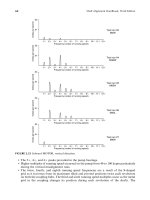
21.1.4 INTERNAL COMBUSTION ENGINES
Very few field studies have been conducted (or at least published) on how internal combustion
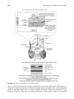
engines move from OL2R conditions (Figure 21.9). Diesel engines, for example, are frequently
used to drive backup electrical generators, fire pumps, and portable air compressors. In the
wastewater treatment industry, biogas engines can be used to drive the air compressors. The
crankshaft is typically set very low in the casing and engine mounts can be found below, at, or
slightly above the centerline of rotation of the crankshaft. The relatively few studies that have
been done have still shown OL2R machinery movement regardless of the casing support
mounting location. Flexible coupling design is somewhat critical since variations in torque
occur as each piston delivers rotational force at varying intervals.
Typical OL2R movement range of internal combustion engines:
Vertical movement: 1 to 5 mils upward (5 to 200 hp); 2 to 20þ mils upward (200þ hp),
typically symmetrical (i.e., inboard and outboard ends move up the same amount)
Piotrowski / Shaft Alignment Handbook, Third Edition DK4322_C021 Final Proof page 673 6.10.2006 12:19am
Alignment Considerations for Specific Types of Machinery 673
Lateral (sideways) movement: 0 to 4 mils (usually much less than any vertical movement)
Axial movement: Unknown
21.1.4.1 Additional Information on Internal Combustion Engines
Moderate to excessive off-line soft foot conditions have been experienced on virtually every
size internal combustion engine regardless of frame construction design. On medium and
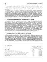
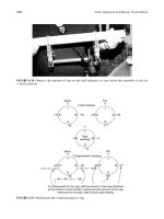
large engines, distortion of the engine frame during installation is a concern. To insure that
the crankshaft bearings are not distorted, web deflection tests are conducted as shown in
Figure 21.11 and Figure 21.12. A web deflection test determines if the distance between the
crank webs is changing when the crankshaft is rotated. If the bearings are misaligned due to
casing distortion, or there is an excessive amount of shaft misalignment with the coupling
engaged, the distance between the crank webs will vary when the crankshaft is rotated. If the
gap variation between the web is excessive, shims must be added between the engine and the
soleplates to relieve the distortion of the casing.
21.1.5 HORIZONTALLY MOUNTED CENTRIFUGAL PUMPS
Without a doubt, one of the most common drive systems in virtually every industry is a
motor-driven, horizontally mounted, centrifugal pump (Figure 21.13 through Figure 21.15).
There are several hundred designs of centrifugal pumps and it would be difficult to cover
every characteristic of each design used in industry. Their purpose is basically to move an
incompressible fluid from point A to point B. The temperature of the fluid conveyed has a
great effect on the OL2R conditions of the pump. As discussed in Chapter 5, the piping
attached to the pump can have a tremendous influence on obtaining and maintaining accurate
alignment, so that many people are unwilling to even try to reposition pumps, henceforth
declaring them the ‘‘stationary’’ machine when aligning them.
Typical OL2R movement range of centrifugal pumps:
Vertical movement: 0 to 80þ mils upward typically asymmetrical (i.e., inboard and out-
board ends do not move up the same amount)
FIGURE 21.9 Sixteen cylinder biogas engine coupled to a gearbox and compressor.
Piotrowski / Shaft Alignment Handbook, Third Edition DK4322_C021 Final Proof page 674 6.10.2006 12:19am
674 Shaft Alignment Handbook, Third Edition
52
60
60
78
78
64
50
50
53
20
32
34
70
76
76
85
89
77
97
107
108
82
92
92
96
100
96
115
121
128
132
132
139
103
105
88
50
3
2
2
10
5
50 20 5
2
2
2
5
5
5
50 20 20
5
5
10
5
50
25
10
3
5
10
2
25
5
2
2
50
25
5
10
2
5
10
20
10
2
2
10
3
North
3
5
5
5
FIGURE 21.10
Soft foot map between engine frame and soleplates on biogas
engine shown in Figure 21.9.
Piotrowski / Shaft Alignment Handbook, Third Edition DK4322_C021 Final Proof page 675 6.10.2006 12:19am
Alignment Considerations for Specific Types of Machinery 675
FIGURE 21.11 Inside dial gauge used to measure web deflection.
1
2
3
4
5
–1/4
–1/4
0
+1/4
+1/4
FIGURE 21.12 Web deflection measurements typically taken at five positions.
FIGURE 21.13 Single-stage centrifugal pumps with overhung impeller.
Piotrowski / Shaft Alignment Handbook, Third Edition DK4322_C021 Final Proof page 676 6.10.2006 12:19am
676 Shaft Alignment Handbook, Third Edition
Lateral (sideways) movement: 0 to 90þ mils (can be much greater than vertical movement
and is usually asymmetrical)
Axial movement: 0 to 150þ mils, frequently dependent on temperature of process fluid
21.1.5.1 Additional Information on Horizontally Mounted Centrifugal Pumps
Moderate to excessive off-line soft foot conditions have been experienced on virtually every
centrifugal pump regardless of frame construction design. Maintaining long-term alignment
of ANSI- and API-type pumps can be difficult due to the loosely supported inboard (coup-
ling) end of the pump case. Failure of mechanical seals can often be attributed to misalign-
ment conditions. Excessive leakage on mechanically packed pumps can also be attributed to
misalignment conditions. Pumps can experience internal rubs due to rotor distortion caused
FIGURE 21.14 Single-stage centrifugal pump with centered impeller.
FIGURE 21.15 Multistage centrifugal pump.
Piotrowski / Shaft Alignment Handbook, Third Edition DK4322_C021 Final Proof page 677 6.10.2006 12:19am
Alignment Considerations for Specific Types of Machinery 677
by moderate to excessive misalignment conditions. Bear in mind that the axial movement
amounts mentioned above are for the casing and housing. The shaft may expand more than
that and may influence how you should set the off-line shaft end to shaft end distances.
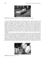
21.1.6 VERTICALLY MOUNTED CENTRIFUGAL PUMPS
There are several different types of vertical pumps such as well water pumps, in-line pumps,
and reactor coolant pumps. In most cases, vertical pumps are driven by C-flanged motors.
These motors are bolted to a cylindrical casting that is attached to the pump casing. In some
situations, the pump is supported in its own bearings and the motor is flexibly coupled to the
pump. In other situations, the pump is rigidly coupled to the motor shaft and the thrust load
is supported by a thrust or radial bearing at the top of the motor. The assumption that many
people have is that no alignment is required for these types of machines since the motor,
connector casting, and pump casing are perfectly machined, rabbeted fits that precisely align
the motor shaft to the pump shaft. In most cases, this is not true. Misalignment can and does
occur on these types of drives as often as a horizontally mounted drive system (Figure 21.16
through Figure 21.18).
Figure 21.19 shows a large vertical pump driven by a 2500-hp motor, which is bolted to the
pump casing with 12 bolts. The pump was new and was experiencing excessive vibration
where misalignment was suspected as the cause. The coupling connecting the motor shaft to
the pump shaft is a rigid coupling. The upper bearing of the motor has a thrust bearing that
supports the weight of the armature and the weight of the pump shaft. Upper and lower
bronze bushings act as the radial bearings for the pump shaft. These bushings are lubricated
by the water that is pumped upward from the impeller at the lower end of the pump shaft.
FIGURE 21.16 Small vertical pumps.
Piotrowski / Shaft Alignment Handbook, Third Edition DK4322_C021 Final Proof page 678 6.10.2006 12:19am
678 Shaft Alignment Handbook, Third Edition
As mentioned previously, any attempt to align shafts that are connected together with a
rigid coupling are futile. The misalignment can be severe and the shafts will elastically bend to
accommodate the misalignment condition making it appear that the alignment is acceptable
when capturing readings across the engaged rigid coupling. To properly align a unit like this,
the coupling must be disengaged. In doing that however, the pump shaft drops down from its
own weight and the impeller touches the housing at the bottom. Any attempt to rotate the
pump shaft after the coupling has been disengaged can potentially damage the impeller. Since
the motor shaft can still be rotated, either the face–rim or double radial alignment methods
could be used. In this particular case, the double radial method was used to check the
alignment between the two shafts. Before disconnecting the coupling however, runout mea-
surements can be taken to determine if the coupling hubs are bored properly (i.e., concentric)
and if the motor or pump shafts are permanently bent. Figure 21.20 shows the runout
measured on the shafts and the coupling hubs.
After the runout measurements were taken, the mechanical seal was removed and the
coupling was disengaged. The specified distance between the end of the motor shaft and
the end of the pump shaft was 0.250 in. There is an adjustment nut on the top of the pump
FIGURE 21.17 Medium-sized vertical pumps.
FIGURE 21.18 Large vertical pumps.
Piotrowski / Shaft Alignment Handbook, Third Edition DK4322_C021 Final Proof page 679 6.10.2006 12:19am
Alignment Considerations for Specific Types of Machinery 679
FIGURE 21.19 Vertical pump.
8 mils
8 mils
11 mils
7 mils
6 mils
12 mils
Angular location of
high spot viewed from
above referenced to
pump key in clockwise
direction
Total indicated
runout (TIR)
290
120
120
120
120
290
As found gap between rotating
mechanical seal cartridge and top of
stuffing box = 0.293 in.
As found adjusting nut to coupling
spool clearance with coupling bolts
removed = 0.263 in.
FIGURE 21.20 Runout measurements taken on pump shown in Figure 21.19.
Piotrowski / Shaft Alignment Handbook, Third Edition DK4322_C021 Final Proof page 680 6.10.2006 12:19am
680 Shaft Alignment Handbook, Third Edition
shaft that can be rotated to obtain the desired shaft-to-shaft distance with the coupling
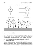
disengaged. The pump shaft was then centered in its upper bushing as shown in Figure
21.21 and Figure 21.22. Feeler gauges were used to measure four points between the shaft
and the bushing as shown in Figure 21.23. The specified total radial clearance in the bushing
was to range from 6 to 12 mils. Notice that the measured gaps exceed the specified amount
and that they are not the same in the east to west direction compared to the north to south
direction.
Now the pump shaft is centered in the upper bushing and the coupling disengaged,
alignment readings can be taken between the shafts. Figure 21.24 shows capturing
the alignment reading on the adjustment nut and Figure 21.25 shows capturing the alignment
reading on the pump shaft just above the stuffing box area. Another reading was taken on
the balance ring just below the adjustment nut. The as-found alignment readings are shown
in Figure 21.26.
To plot the misalignment condition, two views will be generated. One view will show the
misalignment in the north to south direction as shown in Figure 21.27 and another view will
show the misalignment in the east to west direction as shown in Figure 21.28. A T-bar overlay
will be used in this modeling method. The top part of the T-bar overlay will represent
the mating flange surface where the motor bolts to the pump housing. Each bolting plane
has been scaled off on the top part of the T. Carefully study the bolt plane designations in
FIGURE 21.21 Centering the pump shaft in its upper bushing.
Piotrowski / Shaft Alignment Handbook, Third Edition DK4322_C021 Final Proof page 681 6.10.2006 12:19am
Alignment Considerations for Specific Types of Machinery 681
Figure 21.27 and Figure 21.28. The base to the T-bar overlay will represent the centerline of
rotation of the motor shaft.
Since there was runout observed on the motor and pump coupling hubs, before disengaging
the coupling, the shafts were rotated so that the high spots were placed on the north side of
the shafts. With the high spots physically positioned on the north side, we can compensate for
FIGURE 21.22 Wooden wedges were used to keep the pump shaft centered.
North
South
East
West
24 mils
24 mils
8 mils
8 mils
Pump shaft
Upper pump bearing
FIGURE 21.23 Gap measurements at the upper bushing of the pump.
Piotrowski / Shaft Alignment Handbook, Third Edition DK4322_C021 Final Proof page 682 6.10.2006 12:19am
682 Shaft Alignment Handbook, Third Edition
the eccentricity and determine where the actual centerline of rotation of the pump shaft is as
shown in Figure 21.26.
The top part of the T-bar overlay shows what thickness of shims need to be installed
between each of the 12 bolts that mate the motor housing to the pump housing to correct for
the angular misalignment. Bear in mind that each of the 12 flange bolts appear in both views
and that there is an angular misalignment condition in both views. Bolt by bolt, add the
number of shims required to correct the angular misalignment from the north–south and
east–west views. Once the shim totals for each bolt have been added together, determine
FIGURE 21.24 Alignment readings taken at the top of the pump shaft at the adjustment nut.
FIGURE 21.25 Alignment readings taken at the bottom of the pump shaft just above the stuffing box.
Piotrowski / Shaft Alignment Handbook, Third Edition DK4322_C021 Final Proof page 683 6.10.2006 12:19am
Alignment Considerations for Specific Types of Machinery 683
which bolt requires the least amount of shims and subtract that amount from all the bolts as
shown in Figure 21.29. Ironically, the least amount of shims happens to occur at bolt A.
At this point, all of the bolts were loosened and soft foot gaps were measured at each bolt as
shown in Figure 21.30. Improper contact can occur on these types of machines also.
As-found alignment readings
Balance ring
N
S
WE
0
Pump shaft
N
S
W
0
Adjustment nut
N
S
WE
0
0
50
10
40
20
30
+
_
10
40
20
30
0
50
10
40
20
30
+
_
10
40
20
30
0
50
10
40
20
30
+
_
10
40
20
30
14 in.
5.5 in.
4 in.
10.5 in.
+50
0
−53
+54
+4
−53
+58
+14
−49
E
FIGURE 21.26 As-found double radial alignment measurements.
180 wide x 100 tall grid
Apparent pump shaft centerline
(i.e., outer surface with runout)
Scale:
5 in.
and 10 mils
5 in.
and 10 mils
South
North
Balance ring measurement plane
Pump shaft measurement plane
Adjusting nut measurement plane
30.4 in.
22.27 in.
8.
15
in.
63
in.
bolt circle diameter
0NS
0NS
0NS
Adjusting nut
Balance ring
Pump shaft
0
+4
+13
Motor shaft centerli
ne
Apparent motor to pump
housing flange mating plane
F–G bolt plane
add 12 mils
E–H bolt plane
add 11 mils
D–I bolt plane
add 8 mils
C–J bolt plane
add 5 mils
B–K bolt plane
add 2 mils
A–L bolt plane
add 0 mils
Translate 3 mils to the south
Actual pump shaft centerline of rotation
(i.e., compensated for runout)
Adjusted motor to pump
housing flange mating plane
12 mils TIR here
11 mils TIR here
6 mils TIR here
0
50
10
40
20
30
+
_
10
40
20
30
0
50
10
40
20
30
+
_
10
40
20
30
0
50
10
40
20
30
+
_
10
40
20
30
FIGURE 21.27 (See color insert following page 322.) As-found alignment model of motor and pump
shaft as viewed in the north to south direction.
Piotrowski / Shaft Alignment Handbook, Third Edition DK4322_C021 Final Proof page 684 6.10.2006 12:19am
684 Shaft Alignment Handbook, Third Edition
180 wide ϫ 100 tall grid
Pump shaft centerline measurement plane
Scale:
5 in.
and 10 mils
5 in.
and 10 mils
Balance ring measurement plane
Adjusting nut measurement plane
30.4 in.
22.27 in.
8.15 in.
63 in. bolt circle
diamete
r
Adjusting nut
Balance ring
Pump shaft
−103
−107
−107
Motor shaft
centerline
Motor to pump housing
flange mating plane
I–J bolt plane
add 5 mils
H–K bolt plane
add 4 mil
G–L bolt plane
add 3 mils
F–A bolt plane
add 2 mils
E–B bolt plane
add 1 mil
D–C bolt plane
add 0 mils
WestEast
Pump shaft centerline
Translate 51 mils to the west
WE
0
WE
0
WE
0
0
50
10
40
20
30
+
_
10
40
20
30
0
50
10
40
20
30
+
_
10
40
20
30
0
50
10
40
20
30
+
_
10
40
20
30
FIGURE 21.28 (See color insert following page 322.) As-found alignment model of motor and pump shaft as
viewed in the east to west direction.
A
B
CD
E
F
G
H
I
J
K
L
North
South
East
West
13 mils
11 mils
8 mils
4 mils
1 mil
0 mil
1 mil
3 mils
6 mils
10 mils
12 mils
13 mils
3 mils
south
51 mils
west
Note: Highest offset
Bolt ID Shims for north–south view Shims for east–west view Total shims for both views
A
B
C
D
E
F
G
H
I
J
K
0
2
5
8
1
1
1
11
2
2
1
8
5
2
2
1
0
0
1
2
3
4
5
5
4
2
3
5
8
1
1
1
2
14
15
15
3
0
6
L0 3 3
FIGURE 21.29 Shims to correct the angular misalignment and translations to correct the offsets.
Piotrowski / Shaft Alignment Handbook, Third Edition DK4322_C021 Final Proof page 685 6.10.2006 12:19am
Alignment Considerations for Specific Types of Machinery 685
Notice that there is a greater amount of angular misalignment in the north–south direction
than the east–west direction. This is not uncommon with C-flanged equipment. The worst
misalignment condition was not the angular problem but the offset particularly in the east–
west direction. Notice in Figure 21.28 that the motor shaft had to be translated 51 mils to the
west to align it to the pump shaft. To accomplish this, the lateral positioning jackscrews were
adjusted as shown in Figure 21.31.
Despite the fact that this unit had only 20 h of operation on it, the excessive offset
misalignment in the east–west direction was so severe that it damaged the upper pump
bushing as shown in Figure 21.32. This explained why there was an excessive amount of
clearance in the east to west direction of the upper pump bushing as shown in Figure 21.21.
Another design variation in vertical pumps incorporates a shaft extension that is attached
to the end of the pump shaft via a threaded coupling. This shaft extension then goes through a
hollow motor shaft and is then attached to the upper bearing of the motor via a (þ)-shaped
hub with an adjustment nut to raise the pump shaft a specified amount. There are no
Soft foot map
A
B
CD
E
F
G
H
I
J
K
L
North
South
East
West
2
3
3
2
2
2
8
2
2
4
4
0
0
3
4
8
3
2
7
7
2
2
0
0
FIGURE 21.30 Soft foot gap measurements at all the flange bolts.
FIGURE 21.31 Adjusting the jackscrews to correct the offset misalignment.
Piotrowski / Shaft Alignment Handbook, Third Edition DK4322_C021 Final Proof page 686 6.10.2006 12:19am
686 Shaft Alignment Handbook, Third Edition
provisions in this design to align the centerline of rotation of the motor with the centerline of
rotation of the pump shaft similar to the pump previously discussed. The assumption with this
design is that the pump shaft, the pump shaft extension, the motor shaft, the mating flange
surfaces of the motor and pump, the threaded coupling, etc. are all machined to tolerances that
‘‘automatically align’’ the drive system when it is assembled. Problems do occur on these
machines and there are ways to verify that the machining has been done properly so the
alignment is correct. The verification process consists of the following measurements:
1. With the unit assembled, measure the clearance between the pump shaft extension and
the hollow motor shaft as shown in Figure 21.33. Ideally the gaps should be even all the
way around the shaft.
FIGURE 21.32 Excessively worn upper pump bushing due to excessive lateral misalignment.
Clearance between shaft and hollow motor shaft
before removing the adjusting nut
N
S
E 0.385 in. gap0.393 in. gap W
0.390 in. gap
0.399 in. gap
Hollow motor shaft
Pump shaft
FIGURE 21.33 Measured clearances between the pump shaft extension and the hollow motor shaft.
Piotrowski / Shaft Alignment Handbook, Third Edition DK4322_C021 Final Proof page 687 6.10.2006 12:19am
Alignment Considerations for Specific Types of Machinery 687
2. With the unit assembled, measure the runout at several points along the exposed pump
shaft, threaded coupling, and pump shaft extension as shown in Figure 21.34. Also
measure the runout at the upper hub that attaches the pump shaft extension to the upper
motor bearing as shown in Figure 21.35 and Figure 21.36. Ideally the runout should
adhere to the guidelines discussed in Chapter 5.
3. With the motor removed as shown in Figure 21.37, center the pump shaft in its upper
bushing and measure the eccentricity on the pump shaft and the pump shaft extension as
shown in Figure 21.38 through Figure 21.40. This requires fabricating a split collar to
position a rolling element bearing that will be used to hold a bracket and indicator for
1 mil
5 mils
1 mil
1 mil
2 mils
1 mil
FIGURE 21.34 Measured runout at several points along the exposed pump shaft, threaded coupling,
and pump shaft extension.
Piotrowski / Shaft Alignment Handbook, Third Edition DK4322_C021 Final Proof page 688 6.10.2006 12:19am
688 Shaft Alignment Handbook, Third Edition
FIGURE 21.35 Measuring runout on the upper hub.
T–Hub runout
5 mils high opposite the key
The bore appears to be 5 mils
offset toward the key
FIGURE 21.36 Runout at the upper hub that attaches the pump shaft extension to the upper
motor bearing.
Piotrowski / Shaft Alignment Handbook, Third Edition DK4322_C021 Final Proof page 689 6.10.2006 12:19am
Alignment Considerations for Specific Types of Machinery 689
FIGURE 21.37 Remove the motor.
FIGURE 21.38 Measure the eccentricity at the lower end of the pump shaft.
Piotrowski / Shaft Alignment Handbook, Third Edition DK4322_C021 Final Proof page 690 6.10.2006 12:19am
690 Shaft Alignment Handbook, Third Edition
the measurements as shown in Figure 21.41 and Figure 21.42. Ideally the runout should
adhere to the guidelines discussed in Chapter 5.
4. Determine if the pump flange face is centered and perpendicular to the pump shaft as
shown in Figure 21.43 through Figure 21.45. Since the mating flange faces are often
rabbeted fits, the rabbet surface is used to check for concentricity and the flange face
surface is used for perpendicularity checks.
21.1.6.1 Additional Information on Vertically Mounted Centrifugal Pumps
When the motor and pump are bolted together, they effectively become one contiguous frame
and OL2R machinery movement has very little effect on the alignment of the shafts. Since
the entire drive system is typically attached to a floor or the structure of the building,
checks should be made to insure that the motor–pump assembly is firmly attached to the
floor via the anchor bolts. Leakage at the packing gland and frequent replacements of
the mechanical seal are indications that a misalignment condition or excessive runout
may be the culprit. Excessive vibration can often be attributed to unbalance conditions in
the motor armature or pump shafts but can also be traced to excessive runout conditions in the
rotating assembly.
FIGURE 21.39 Measure the eccentricity at the upper end of the pump shaft.
Piotrowski / Shaft Alignment Handbook, Third Edition DK4322_C021 Final Proof page 691 6.10.2006 12:19am
Alignment Considerations for Specific Types of Machinery 691
21.1.7 BLOWERS AND FANS
There are several different designs of fans and blowers and again, it would be difficult to cover
every aspect of these types of machines. Similar to pumps, their purpose is basically to move
large volumes of a compressible fluid at low pressures from point A to point B. A large majority
of smaller horsepower (5 to 200 hp) units are belt-driven as shown in Figure 21.46. Larger units
are more frequently direct-driven as shown in Figure 21.47 and Figure 21.48. Again, the
temperature of the gas that is conveyed has a great effect on the OL2R conditions of the fan.
As discussed in Chapter 5, the ductwork attached to the fan can have a tremen-
dous influence on obtaining and maintaining accurate alignment, so that many people are
Total indicated
runout (TIR)
0
N
S
E −2W
0
N
S
EW
0
N
S
EW
0
−2.5
+16.5 +3
+1
+18 +4
+4
−7.5
N
S
EW
0
−0.5 −4
N
S
EW
0
+3 −1
−2.5
View from above when
runout measurements
were taken
N
S
EW
Key
0
50
10
40
20
30
+
_
10
40
20
30
5 in.
6 in.
20 in.
44 in.
11.25 in.
FIGURE 21.40 Eccentricity measurements along the pump shaft and its extension.
Piotrowski / Shaft Alignment Handbook, Third Edition DK4322_C021 Final Proof page 692 6.10.2006 12:19am
692 Shaft Alignment Handbook, Third Edition
unwilling to even try to reposition fans and blowers and henceforth declare them the
‘‘stationary’’ machine when aligning them. In some situations, where the fan blades are center
mounted on the shaft and the shaft is supported by bearings at each end, the position of
the shaft is dictated by the positions of the bearing pedestals that are not directly attached
to the fan housing. The fear in altering the position of the fan bearings is that internal fan
blade to shroud clearances could be upset and rubs could occur. Here again, the graphing or
modeling technique can be used not only to align the shafts, but also to position the fan
housing to properly set fan blade to shroud clearances.
FIGURE 21.41 Split collar and bearing.
FIGURE 21.42 Bracket attached to outer race of rolling element bearing held in place with the split collar.
Piotrowski / Shaft Alignment Handbook, Third Edition DK4322_C021 Final Proof page 693 6.10.2006 12:19am
Alignment Considerations for Specific Types of Machinery 693
Figure 21.49 shows a motor-driven fan, where the fan shaft and wheel are supported on
pedestals that are separated from the fan housing itself. It is possible for the centerline of the
fan housing not to be collinear with the centerline of rotation of the fan shaft. To determine
where the center of the fan housing is, take gap measurements between the fan wheel and
the shroud at the top, bottom, and both sides at the inboard and outboard ends. For example,
top and bottom gap measurements were taken between the fan wheel and the stationary
FIGURE 21.43 Checking for concentricity on the rabbeted surface.
FIGURE 21.44 Checking for perpendicularity on the flange surface.
Piotrowski / Shaft Alignment Handbook, Third Edition DK4322_C021 Final Proof page 694 6.10.2006 12:19am
694 Shaft Alignment Handbook, Third Edition