Handbook of Shaft Alignment Part 17 pps
Bạn đang xem bản rút gọn của tài liệu. Xem và tải ngay bản đầy đủ của tài liệu tại đây (2.02 MB, 50 trang )
____ Yes
Course title __________
Fee per student charge _____ (U.S. dollars)
Fee per course charge _____ (U.S. dollars)
____ minimum number of attendees
____ maximum number of attendees
____ Yes
Course title __________
Fee per student charge _____ (U.S. dollars)
Fee per course charge _____ (U.S. dollars)
____ minimum number of attendees
____ maximum number of attendees
4. Do you provide classroom material for each student? If so, describe the training material
(e.g., books, course notes, CD, etc.) that each student receives in the course.
____ No
____ Yes
Course title __________
Course material __________
____ Yes
Course title __________
Course material __________
____ Yes
Course title __________
Course material __________
5. Can the classroom material be purchased without attending the course? If so, what is the
cost of the classroom material?
_____ (U.S. dollars)
6. Do the attendees perform hands-on work on alignment training simulators in the
course? If so, indicate the number of students per training simulator.
____ no training simulators used
____ 1 student per training simulator
____ 2 students per training simulator
____ 3 students per training simulator
____ 4–6 students per training simulator
____ 1 training simulator for entire class
____ 1 training simulator for instructor only
____ Others, describe __________
7. Can a training simulator be purchased? If so, what is the cost of the training simulator?
_____ (U.S. dollars)
8. Please indicate what topics are taught in your course(s) and whether it is covered in a
lecture (LCTR), and=or a real life example or case history (XMPL), and=or if it is
practiced with the hands-on training simulators (LAB):
LCTR XMPL LAB Content
____ ____ ____ Symptoms of misaligned rotating machinery
____ ____ ____ Definition of shaft misalignment
____ ____ ____ Alignment tolerance guidelines
Piotrowski / Shaft Alignment Handbook, Third Edition DK4322_A001 Final Proof page 770 29.9.2006 7:46pm
770 Shaft Alignment Handbook, Third Edition
____ ____ ____ Difference between alignment and flexible coupling tolerances
____ ____ ____ Design principles of flexible and rigid couplings
____ ____ ____ Finding and correcting coupling problems
____ ____ ____ Design principles of bearings
____ ____ ____ Static and dynamic forces in machinery
____ ____ ____ Using vibration analysis to detect misalignment
____ ____ ____ Using infrared thermography to detect misalignment
____ ____ ____ Step-by-step procedure for the alignment process
____ ____ ____ How much time each step of the alignment process requires
____ ____ ____ How to measure runout on mechanical couplings and machinery shafts
____ ____ ____ What causes excessive runout conditions
____ ____ ____ Finding and correcting soft foot conditions
____ ____ ____ Finding and correcting excessive piping strain
____ ____ ____ Face–rim alignment method
____ ____ ____ Reverse indicator alignment method
____ ____ ____ Double radial alignment method
____ ____ ____ Shaft to coupling spool alignment method
____ ____ ____ Face–face alignment method
____ ____ ____ Measure and compensate for bracket=bar sag
____ ____ ____ Validity rule for alignment measurements
____ ____ ____ Mathematical corrections for face–rim
____ ____ ____ Mathematical corrections for reverse indicator
____ ____ ____ Mathematical corrections for double radial
____ ____ ____ Mathematical corrections for shaft to coupling spool
____ ____ ____ Mathematical corrections for face–face
____ ____ ____ Alignment graphing=modeling for face–rim
____ ____ ____ Alignment graphing=modeling for reverse indicator
____ ____ ____ Alignment graphing=modeling for double radial
____ ____ ____ Alignment graphing=modeling for shaft to coupling spool
____ ____ ____ Alignment graphing=modeling for face–face
____ ____ ____ Basic operating principle of all laser alignment systems
____ ____ ____ Basic operating principle for a specific laser alignment system
____ ____ ____ Aligning multiple element drive trains
____ ____ ____ Aligning right angled drives
____ ____ ____ Aligning vertically oriented shafts
____ ____ ____ Off-line to running (OL2R) machinery movement basics
(aka ‘‘hot’’ and ‘‘cold’’ alignment)
____ ____ ____ Calculated machine case thermal expansion method
____ ____ ____ Inside micrometer-tooling ball-angle measurement methods
____ ____ ____ Proximity probes with water-cooled stands method
____ ____ ____ Optical alignment tooling method
____ ____ ____ Alignment bars with proximity probes method
____ ____ ____ Laser–detector systems method
____ ____ ____ Rod-tubing connector system method
____ ____ ____ Vernier-strobe method
____ ____ ____ Other OL2R machinery movement methods
____ ____ ____ Compensating for OL2R machinery movement
____ ____ ____ Other topics _____
____ ____ ____ Other topics _____
____ ____ ____ Other topics _____
____ ____ ____ Other topics _____
____ ____ ____ Other topics _____
____ ____ ____ Other topics _____
____ ____ ____ Other topics _____
Piotrowski / Shaft Alignment Handbook, Third Edition DK4322_A001 Final Proof page 771 29.9.2006 7:46pm
Appendix H 771
9. Do you offer or provide testing or exams for your courses? If so, what is the cost of the
exams?
Exam description _____
Exam cost _____ (U.S. dollars)
Exam description _____
Exam cost _____ (U.S. dollars)
Exam description _____
Exam cost _____ (U.S. dollars)
Exam description _____
Exam cost _____ (U.S. dollars)
10. Are your tests or exams recognized by a professional affiliation or organizations? If so,
what are the professional affiliation or organizations?
Professional affiliation or organizations:
__________
__________
__________
__________
__________
11. Please indicate the number of years of experience of the training instructor(s), their
previous job functions and time in that job, and educational experience.
Instructors name _____
Training experience _____ years
Alignment field experience _____ years
Number
of Years Job Description
_____ Plant manager
_____ Engineering manager
_____ Maintenance manager
_____ Mechanical engineer
_____ Electrical engineer
_____ Civil engineer
_____ Industrial engineer
_____ Other engineers, _____
_____ Front line supervisor=foreman=planner
_____ Technician
_____ Mechanic
_____ Millwright
_____ Pipefitter
_____ Electrician
_____ Electronic repair=instrumentation
_____ Others (please list) __________
Formal Training
_____ K–12 (elementary education)
_____ Trade school
_____ Junior college
_____ Bachelor’s degree
_____ Master’s degree
Piotrowski / Shaft Alignment Handbook, Third Edition DK4322_A001 Final Proof page 772 29.9.2006 7:46pm
772 Shaft Alignment Handbook, Third Edition
_____ Doctoral degree
Instructors name __________
Training experience _____ years
Alignment field experience _____ years
Number
of Years Job Description
_____ Plant manager
_____ Engineering manager
_____ Maintenance manager
_____ Mechanical engineer
_____ Electrical engineer
_____ Civil engineer
_____ Industrial engineer
_____ Other engineers, _____
_____ Front line supervisor=foreman=planner
_____ Technician
_____ Mechanic
_____ Millwright
_____ Pipefitter
_____ Electrician
_____ Electronic repair=instrumentation
_____ Other (please list) __________
Formal Training
_____ K–12 (elementary education)
_____ trade school
_____ junior college
_____ Bachelor’s degree
_____ Master’s degree
_____ Doctoral degree
12. Additional information
__________
__________
__________
__________
__________
Piotrowski / Shaft Alignment Handbook, Third Edition DK4322_A001 Final Proof page 773 29.9.2006 7:46pm
Appendix H 773
Piotrowski / Shaft Alignment Handbook, Third Edition DK4322_A001 Final Proof page 774 29.9.2006 7:46pm
Appendix I
Shaft Alignment Services
Questionnaire
If you decide that you would like to have an outside contractor perform shaft alignment
services for you, this questionnaire should help in assessing the qualifications of the company
or personnel who will be performing the services.
1. Indicate what geographical area your alignment services cover (cities, states, countries,
etc.).
__________
__________
__________
__________
__________
__________
__________
2. Indicate what types of industrial rotating machinery you have worked on and for what
period of time.
Number
of Years Machinery Type
_____ Synchronous motors
_____ Induction motors
_____ Steam turbines
_____ Gas turbines
_____ Water turbines
_____ Internal combustion engines
_____ Drivers up to 50 hp
_____ Drivers from 50 to 200 hp
_____ Drivers from 200 to 1000 hp
_____ Drivers from 1000 to 5000 hp
_____ Drivers from 5000þ hp
_____ Single stage centrifugal pumps
_____ Multiple stage centrifugal pumps
_____ Centrifugal air compressors
_____ Reciprocating air compressors
_____ Screw or sliding vane air compressors
_____ Gearboxes
_____ Fans
_____ Blowers
_____ AC generators
_____ DC generators
_____ Cooling tower fan drives
Piotrowski / Shaft Alignment Handbook, Third Edition DK4322_A001 Final Proof page 775 29.9.2006 7:46pm
775
_____ Multiple element drive trains
_____ Other machinery (please list)
_____
_____
_____
3. Please fill out the following form for each employee performing shaft alignment in your
organization. If there are several employees who perform these functions, please attach
their information to this questionnaire.
Part A. Job description
Indicate the number of years of experience of the service personnel, their current job
function(s), time in that job, and educational experience. If they perform more than one
function, please indicate each one.
Service personnel name __________
Alignment field experience _____ years
Number
of Years Job Description
_____ Company president or director
_____ Department manager
_____ Engineering manager
_____ Service manager
_____ Mechanical engineer
_____ Electrical engineer
_____ Civil engineer
_____ Industrial engineer
_____ Other engineers, _____
_____ Front line supervisor=foreman=planner
_____ Technician
_____ Mechanic
_____ Millwright
_____ Pipefitter
_____ Electrician
_____ Electronic repair=instrumentation
_____ Others (please list) _____
Part B. Education
_____ K–12 (elementary education)
_____ Trade school
_____ Junior college
_____ Bachelor’s degree
_____ Master’s degree
_____ Doctoral degree
Part C. Alignment training
Indicate what training you have received in the following shaft alignment methods, pro-
cedures, or tasks. Formal training means they attended a training course, on the job training
(OTJT) means you where shown this information by a coworker or you were self taught.
Formal OTJT Shaft Alignment Method(s), Procedures, Tasks
_____ _____ Foundation and baseplate=soleplate installation and repair
_____ _____ Soft foot detection and correction
_____ _____ Excessive runout detection and correction
Piotrowski / Shaft Alignment Handbook, Third Edition DK4322_A001 Final Proof page 776 29.9.2006 7:46pm
776 Shaft Alignment Handbook, Third Edition
_____ _____ Excessive piping strain detection and correction
_____ _____ Straightedge, eyeball, feeler gauge
_____ _____ Face–rim indicator
_____ _____ Reverse indicator
_____ _____ Shaft to coupling spool
_____ _____ Double radial
_____ _____ Face–face
_____ _____ Laser=detector system(s), model(s)_____
_____ _____ Calculating ‘‘growth’’ using the thermal strain equation
_____ _____ Inside micrometer=tooling ball=angle measurement devices
_____ _____ Proximity probes with water-cooled stands
_____ _____ Optical alignment tooling
_____ _____ Alignment bars and proximity probes (aka ‘‘Dodd’’=Dynalign bars)
_____ _____ Laser=detector dystem(s), model(s)_____
_____ _____ Ball-rod-tubing connector system
_____ _____ Vernier-strobe method
_____ _____ Instrumented coupling system
_____ _____ Shaft alignment software programs
_____ _____ Others (please list) _____
Part D. Shaft alignment field experience
Indicate what off-line shaft alignment methods you have performed and for what period of
time.
Number
of Years Shaft Alignment Method(s) You Have Used
_____ None
_____ Eyeball
_____ Straightedge, eyeball, feeler gauge
_____ Face–rim indicator
_____ Reverse indicator
_____ Shaft to coupling spool
_____ Double radial
_____ Face–face
_____ Optical alignment tooling
_____ Laser=detector system(s), model(s) _____
_____ Others (please list)_____
_____
_____
_____
Indicate what off-line to running (OL2R) machinery movement measurement and align-
ment compensation methods (aka ‘‘hot’’ and ‘‘cold’’ alignment) you have performed and for
what period of time.
Number
of Years OL2R Machinery Movement Measurement Method(s) You Have Used
_____ Calculating machine case thermal expansion (thermal strain equation)
_____ Inside micrometer=tooling ball=angle measurement devices
_____ Proximity probes with water-cooled stands
_____ Optical alignment tooling
_____ Alignment bars and proximity probes (aka ‘‘Dodd’’ bars=Dynalign system)
_____ Laser=detector system(s), model(s) _____
Piotrowski / Shaft Alignment Handbook, Third Edition DK4322_A001 Final Proof page 777 29.9.2006 7:46pm
Appendix I 777
_____ Ball-rod-tubing connector system
_____ Vernier-strobe method
_____ Instrumented coupling system
_____ Others (please list)_____
__________
__________
Part E. Additional talents and capabilities
Indicate any additional tasks you have performed and for what period of time.
Number
of Years Skills or Tasks
_____ Vibration analysis or monitoring
_____ Shop balancing
_____ Field balancing
_____ Infrared thermography surveys
_____ Oil analysis
_____ Motor current signature analysis
_____ Motor testing
_____ Root cause failure analysis (RCFA)
_____ Machinery overhaul and repair
_____ Sliding bearing inspection, replacement, or repair
_____ Rolling element bearing inspection or replacement
_____ Rigging
_____ Foundation installation (i.e., concrete, re-bar, forms, isolation, etc.)
_____ Basic machine tool operation (e.g., lathe, mill, grinder)
_____ Gas welding and cutting
_____ MIG welding
_____ TIG welding
_____ Pipefitting
_____ Hand tools (e.g., wrenches, ratchets, etc.)
_____ Basic measuring tools (micrometers, dial indicators, slide calipers, etc.)
_____ Power tools (e.g., drills, grinders, saws, air tools, etc.)
_____ Fork truck operation
_____ Crane operation
_____ Lubrication
_____ Flexible or rigid coupling inspection or replacement
_____ Oil seal inspection or replacement
_____ Mechanical packing inspection or replacement
_____ Mechanical seal inspection or replacement
_____ Pneumatic instrumentation
_____ Electronic instrumentation
_____ Hydraulics
_____ Basic computer skills
_____ Word processing software
_____ Database or spreadsheet software
_____ Presentation software
_____ CAD
_____ Illustration=graphics software
_____ Desktop publishing software
_____ Digital photography
Piotrowski / Shaft Alignment Handbook, Third Edition DK4322_A001 Final Proof page 778 29.9.2006 7:46pm
778 Shaft Alignment Handbook, Third Edition
_____ Digital video
_____ Local area network installation and maintenance
_____ Internet and web browsers
_____ Software programming languages (e.g., C, Pascal, Basic, Fortran, etc.)
_____ Other skills (please list)
_____
_____
_____
_____
Part F. Certification or accreditation
Indicate any certification or achievements related to your work. Please show what level of
achievement (e.g., Levels 1, 2, 3, etc.) was received, and the organization or institution the
achievement was received from (e.g., ISO, ANSI, ASME, Vibration Institute, JATC, college,
trade school, company, etc.).
Level Organization Subject or Skill
_____ _____ Shaft alignment
_____ _____ Optical alignment
_____ _____ Vibration analysis
_____ _____ Balancing
_____ _____ Infrared thermography
_____ _____ Oil analysis
_____ _____ Motor current signature analysis
_____ _____ Motor testing
_____ _____ Root cause failure analysis (RCFA)
_____ _____ Machinery overhaul and repair
_____ _____ Rigging
_____ _____ Machine tool operation
_____ _____ Gas welding and cutting
_____ _____ MIG welding
_____ _____ TIG welding
_____ _____ Pipefitting
_____ _____ Fork truck operation
_____ _____ Crane operation
_____ _____ Lubrication
_____ _____ Pneumatic instrumentation
_____ _____ Electronic instrumentation
_____ _____ Hydraulics
_____ _____ Basic computer skills
_____ _____ Word processing software
_____ _____ Database or spreadsheet software
_____ _____ CAD
_____ _____ Software programming languages
_____ _____ Others _____
_____ _____ Others _____
_____ _____ Others _____
_____ _____ Others _____
Piotrowski / Shaft Alignment Handbook, Third Edition DK4322_A001 Final Proof page 779 29.9.2006 7:46pm
Appendix I 779
Piotrowski / Shaft Alignment Handbook, Third Edition DK4322_A001 Final Proof page 780 29.9.2006 7:46pm
Appendix J
Alignment Internet Web Sites
Company or Organization Web Site
Accushim Inc. http:==www.accushim.com=v180.html
Alignment Services Inc. http:==www.alignmentservicesinc.com=
Alignment Supplies Inc. http:==www.alignmentsupplies.com=
Automated Precision http:==www.apisensor.com=
Brunson Instrument Co. http:==www.brunson.us=
Aline Mfg. Inc. http:==alinemfg.com=
Damalini http:==www.damalini.com=
Donaldson Garrett & Associates Inc. http:==www.dg-a.com=
Dreyco Mechanical Services Inc. http:==www.dreyco-mechanical.com=index.asp
Fixturlaser http:==www.fixturlaser.com=
James L. Griffin Co. Inc. http:==www.jlgriffin.com=
Hamar Laser http:==www.hamarlaser.com=
Indikon Co. Inc. http:==www.indikon.com=
Kara Co. http:==www.karaco.com=
Laser Tools Co. Inc. http:==www.lasertoolsco.com=
Ludeca http:==www.ludeca.com=
Newman Tools Inc. http:==www.newmantools.com=shaft.htm
New Standard Institute http:==www.newstandardinstitute.com=index.cfm
Oasis Alignment Services http:==www.oasisalignment.com=
Oxford Engineering Co. http:
==www.oxfordengineeringco.com=
Peterson Alignment Tools co. http:==www.petersontools.com=
Pinpoint Laser Systems http:==www.pinlaser.com=
Pruftechnik http:==www.pruftechnik.com=index__.htm
R&T Factors Inc. http:==rtfactors.com=
Schaeffer Precision Alignment Inc. http:==www.schaefferprecision.com=
SPM Instrument http:==www.spminstrument.com=
Turbine Tools http:==www.turbinetools.com=
Turvac Inc. http:==www.turvac.com=
Unisorb http:==www.unisorb.com=
Universal Technologies Inc. http:==www.unitechinc.com=
Update International http:==www.update-intl.com=
Vibralign http:==www.vibralign.com=
Piotrowski / Shaft Alignment Handbook, Third Edition DK4322_A001 Final Proof page 781 29.9.2006 7:46pm
781
Piotrowski / Shaft Alignment Handbook, Third Edition DK4322_A001 Final Proof page 782 29.9.2006 7:46pm
Appendix K
Single Plane Balancing
Single plane balancing procedure
Induction motor
Synchronous motor
DC motor
Steam turbine
Gas turbine
Water turbine
Diesel
Centrifuge
Other
To operate this window . . .
Compressor
ANSI/API pump
Centrifugal pump
Fan/blower
Cooling tower fan
Gear
Roll
Flywheel
Generator
OK
American Electric Co.
PH 125
S-44678
4250
Balanced by . . . Name
Enter all the information on the machine being balanced, then press ‘OK’.
Machine Information
Gather some information on the type of machine
your are going to be balancing as shown below. If you
ever need to balance this machine again, you can go
back and review all of this information to reduce the
amount of time required for re-balancing.
1.
Record the information on the balance analyzer,
type of vibration sensor used, vibration engineering
units, and phase angle measuring device used. This is
critical information for future balance runs.
2.
Piotrowski / Shaft Alignment Handbook, Third Edition DK4322_A001 Final Proof page 783 29.9.2006 7:46pm
783
Single plane
applications
Select the closest rotor configuration for
the sunchronous mortor you're trying to balance.
Centered thin rotor
To operate this window . . .
Centered multi-disk
Overhung wide rotor
Overhung thin rotor
Long thin rotor
Centered wide rotor
OK
Rigid rotor types
Usually, single plane balancing can be performed on
the types of rotors shown inside the dashed box below.
The other rotor types shown below could be single plane
balanced but usually require two plane balancing.
3.
Single plane balancing procedure
Record the information on the placement/location of
the vibration sensor and the phase angle measuring
device. This is critical information for future balance
runs.
4.
Enter the vibration & 1/rev sensor postions, the viewing
direction, and the direction of rotation.
Piotrowski / Shaft Alignment Handbook, Third Edition DK4322_A001 Final Proof page 784 29.9.2006 7:46pm
784 Shaft Alignment Handbook, Third Edition
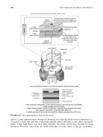
.
Gather some information on the rotor weight, the
normal operating speed of the rotor, and where you are
going to be installing the trial and/or correction
weights. This is critical information for calculating the
right amount of trial weight so you get a good response
without damaging the machine trying to balance it.
5.
Enter the date to determine the optimum trial weight.
Single plane balancing procedure
.
“Original” unbalanced run
vibration amplitude and
phase angle data
Operate the rotor at the balancing speed, and with
your analyzer filter tuned to the rotating speed of
the rotor (i.e., 1 x RPM). Proceed to measure and
record the original unbalance amplitude and phase
data. This will be called the “Original” or “O” vector.
6.
Piotrowski / Shaft Alignment Handbook, Third Edition DK4322_A001 Final Proof page 785 29.9.2006 7:46pm
Appendix K 785
Stop the r
otor and add a trial weight to the part. The trial
weight should produce a force equal to 10% of the static
weight of the rotor on one bearing. Record the amount of
the trial weight (in ounces or grams) and the distance from
the centerline of rotation (in inches or centimeters). Insure
that the trial weight is firmly attached to the rotor.
where:
Trial weight = ounces in English system or grams in metric system
F = 10% of the static rotor weight (pounds in English system or
kilograms in Metric system)
R = radius of the trial weight from the centerline of rotation (inches in
English system or centimeters in Metric system)
N = rotor speed/1000 (RPM/1000)
K = 1.77 (English system) or 0.011 (Metric system)
Trial weight =
K x R x N
2
F
Weight Amount
Angular Location
4
90
oz.
degrees
0
30
60
90
120
150
180
210
240
270
300
330
+
TW
“Trial Weight”
Installation
?
Suggested Trial Weight Amount = 2.57 oz.
OK
Stop the machine and install a trial weight on the rotor.
Enter the trial weight amount and angular location.
To operate this window . . .
7.
Single plane balancing procedure
Piotrowski / Shaft Alignment Handbook, Third Edition DK4322_A001 Final Proof page 786 29.9.2006 7:46pm
786 Shaft Alignment Handbook, Third Edition
Restart the machine and operate the rotor at the
balancing speed. Observe and record the new unbalance
amplitude and phase data. This will be called the “original
plus trial weight” vector (O+T).
“Trial Weight” run
vibration amplitude and
phase angle data
Amplitude
Phase Angle
0.8
30
in/sec
degrees
0
30
60
tach
90
120
150
180
210
240
270
300
330
+
vibs
TW
OK
To operate this window . . .
Re-start the machine with the trial weight on the rotor.
Enter the vibration amplitude and phase angle data.
8.
Single plane balancing procedure
Piotrowski / Shaft Alignment Handbook, Third Edition DK4322_A001 Final Proof page 787 29.9.2006 7:46pm
Appendix K 787
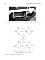
On a sheet of polar graph paper, plot the “original run vector” (called
the “O” vector, the “original plus trial weight vector” (called the “O+T”
vector). Construct the “trial weight effect” vector (aka the “T” vector)
by connecting the ends of the “original” and “trial weight” vectors. The
“T” vector should point from the “O” vector to the “O+T” vector.
9.
0
10
20
30
40
50
60
70
80
90
100
110
120
130
140
150
160
170
180
190
200
210
220
230
240
250
260
270
280
290
300
310
320
330
340
350
*Notice that the
angular shift from
the “O” vector to the
“O+T” vector was a
counterclockwise
shift.Therefore,
the correction
weight should be
placed ina
clockwise
direction from its
trial weight position
(57 + 90 = 147).
“T” vector
0.59 ips at 57Њ
57
o
“O+T” vector
0.8 ips at 30Њ
“O” vector
0.5 ips at 120Њ
Single plane balancing procedure
Piotrowski / Shaft Alignment Handbook, Third Edition DK4322_A001 Final Proof page 788 29.9.2006 7:46pm
788 Shaft Alignment Handbook, Third Edition
Using a protractor, measure the included angle between the “O”
and “T” vectors. This will be called the “correction” angle
.
Mark the spot where the trial weight is located and remove the trial
weight. Install the correction weight at an angular amount equal to the
“correction” angle from the point where the trial weight was located but
in a direction opposite of the phase shift from the “O” vector to the
“O+T” vector. Make sure the correction weight is installed at the same
radius from the centerline of rotation as the trial weight.
14.
In the future, if you place the vibration and phase angle sensors in
the same place, all you need do is measure and record the amplitude
and phase angle data, plot it on a new piece of graph paper as the “O+T”
vector along with the “O” vecor, draw a new “T” vector, plug it into the
correction weight formula above and you have the new correction weight
y
ou need. Good luck and
g
reat balancin
g
!
Correction weight = trial weight ×
“original” vector amplitude
“trial weight effect” vector amplitude
Weight Amount
Angular Location
2.1 oz.
147 degrees
0
30
60
90
120
150
180
210
240
270
300
330
+
CW
The trial weight must be removed and the above weight
should be added at the angular location shown.
“Correction Weight” Information
Measure the length of the “trial weight effect” vector and use the
formula to determine the correct balance weight needed
10.
11.
12.
Run the rotor again and record the vibration and phase angle data.
If everything went OK, the rotor should now be balanced. If additional
“trim balancing” is required,use this latest amplitude and phase data
as a new “O+T” vector and plot it on a new polar graph paper along
with the original “O” vector. Draw a new “T” vector and re-calculate the
new correction weight. Repeat as often as necessary.
13.
Single plane balancing procedure
Piotrowski / Shaft Alignment Handbook, Third Edition DK4322_A001 Final Proof page 789 29.9.2006 7:46pm
Appendix K 789
Piotrowski / Shaft Alignment Handbook, Third Edition DK4322_A001 Final Proof page 790 29.9.2006 7:46pm
Index
A
A-Line systems 274–275
A-String
sheave alignment 605–606
accelerometer 40–41
Acculign system 486–487
Accushim, Inc. 274–275
Accushim systems 273
adhesive backed targets 511
adjusting belt tension 595–596
air gap clearance problems 703
air gap measurements 703–705
aligning bent shafts 8, 201
aligning two hollow cylinders 622–626
aligning vertically oriented rotating
machinery 249
alignment
history of 735–751
alignment accuracy 344
alignment and coupling tolerances 341–352
alignment bars 515–522
alignment bars with proximity probes
515–522
alignment certification 26–31
alignment laws
of multiple element drive trains 564 –566
alignment modeling 319–339, 347–348, 354,
606–612, 655, 697, 703
cardinal rules 361
for 3 bearing machines 703–705
for barrels and cylinders 622
for vertical generators 707–719
of multiple element drive
trains 588–589
of parallel rolls 639–640
of vertical pumps 678–679
to center rotors in housing 668
alignment qualifications 26–27
alignment records 2, 33
alignment skills 19–23
alignment skills testing 19–23
alignment software 273–274
alignment solutions 319, 567
alignment steps 7
alignment survey 2–3
alignment tolerances 7, 14, 17–19, 52, 53, 135,
138, 220
factors affecting 345
alignment tools 277–280
alignment training 12–13
alignment troubleshooting 311–315
allowable lateral movement envelope 336
finding 336
allowable lateral restrictions 321
allowable movement envelope 334–337, 565
allowable movement map 304
alternating current electric generator 702
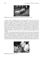
anchor bolts 102–103, 109–111, 114, 118, 126
protecting 112–113
angular measurements
definition of . . . 343
angular misalignment 342
antifriction bearings 296
API Spec 686 118
arcsecond 341, 626
artificial face surface 385–387
asymmetrical bracket 363
axial distance 297
axial float 376, 379
axial flow compressor 481, 673
axial movement 155, 376
axial position 186, 296
axial spacing 296–297
axial spacing for a gear coupling 298
B
backside face readings 462
balance 144
in gear coupling 140–150
balancing 23, 424
balancing rotors 19
ball mill drive 563
Ball–Rod–Tubing connector system 476, 531, 545
barrel alignment 619–622
baseline data 19
basement floor 334–335
baseplates 89–91, 98–100, 109–110, 129
cast 92, 109–110, 128
checking 313
distortion of 94, 99, 118, 126
Piotrowski / Shaft Alignment Handbook, Third Edition DK4322_C023 Final Proof page 791 28.9.2006 11:01am
791
fabricated 92–110
grinding 19, 567
intentional distortion 99, 495
interface problems 179
levelling 118
levelness of 342
preparation 111–112
problems with 17
stress relieve 99
baseplate restriction point 334 –335
basic alignment models 321–323
beam dispersion 414
bearing
skidding or spinning 182–183
bearings
overheated 4 –5
bearing alignment 619
bearing loads 19, 496
bearing pedestals 693, 703–704
belt drives
advantages & disadvantages 591
alignment of 591–618
belt length
calculating 595–596
belt tension 591, 593, 595–596
belt tension gauge 595–596
belt wear indicator 594
Benchmark system 276
bending stresses 314, 389
biogas compressor 698
biogas engine 673
blowers
alignment considerations for 692–697
blue check 184
boiler feedwater pump 298
bolt bound 53, 292, 336, 423, 554
bolt bound conditions 292–294, 336, 419 , 655
modeling of 419–420
bore alignment 619–638
using Double Radial method 679
bore sighting targets 622–623
boundary conditions 634–635
bracket=bar sag 267–269
bracket sag 253, 267–269, 315, 325–326, 654
compensating for 326
brass shims 300
bucking in 631–638
bucking in process 631–638
C
C-flanged motors 678
carbon steel shims 300
Cardan error 153, 653
case distortion from thermal expansion 490
catenary curve 349–350, 703, 740
CCD 241–245
cement 104 –105
centrifugal pumps 674, 674, 691–692
alignment considerations for 674 –678
chainfalls 133, 306, 706
chain couplings 140
charge-coupled device 244, 316
chiller 698, 702
chiller compressor 698, 702
Christmas tree brackets 269
clutch 20, 489, 719
coefficients of thermal expansion 477– 478
coincidence level calibration test, aka Peg
Test 234, 509
collimate 647
collinear
definition of 344
comealongs 306
compensated readings 268
compensate for axial movement
during alignment 376
compressor 472
compressors 701–702
alignment considerations for 698–701
concrete 104–105
compressive strength 98, 104 –105
curing 99, 104–105
time to cure 291
vibrators 99
Condition Based Maintenance 35–37
cone of runout 714
cone orbit diameter
in vertical generators 714
continuous lube oil system
in gears 719
converting vibration units 45
cooling tower fan drive 722–724
alignment considerations for 727
coordinate optical micrometer 622
coplanar
definition of 639–641
corrective moves 319, 332–333, 425, 586
coupling 153, 344
flexing points 345–347, 722–723
maximum misalignment tolerance 137–138
couplings
continuous oil feed 163
design criteria 138–139
disk=diaphragm 75, 147
elastomeric 156–158, 164
flexible & rigid 137–139, 591
history of 137
hydraulically installed 172–173
Piotrowski / Shaft Alignment Handbook, Third Edition DK4322_C023 Final Proof page 792 28.9.2006 11:01am
792 Shaft Alignment Handbook, Third Edition
hydraulic expansion 172–175
installation of 173–174
interference fits 168–170
keyless taper bores 172
lubrication of 140
mechanically flexible 74
miniature 139–141
removal of 170, 175
role of 138
thermal expansion for installation 169
thermal or hydraulic expansion 172–174
tolerances of 137–138
types of 75, 78
windage 518
coupling alignment 348
coupling bolts 314
coupling hub
contact pressure 173
slippage 172–173
coupling hub surface contact 171–172
coupling lockup 297
coupling tolerances 138, 348–349
crankshaft 673–774
cubit 735
curved axis of rotation 350
custom shims 300
cutlass bearings 188
cutting shims 300
cylinder alignment 627–631
D
Damalini Systems 416–418
damping 39– 40
desired off-line positions 315, 476
desired off-line shaft positions 540–548
dial indicator 134, 180–181, 187–188, 205, 212
basic operation of 180
inventor of 744, 751
dial indicator manufacturer pricing,
specifications, and features 284–285
diaphragm couplings 75, 158–159
diesel engines
for generators 703
die penetrant checks 192
disc couplings 161
Doppler effect 244
Double Dial method 353
Double Radial Method 389–395, 679
for bore alignment 620–622
Double Radial method
for vertical pumps 391–392
Double Radial Method mathematics 392
Double Radial shoot for dial indicator
readings 548
dowel pin 490
dowel pins 721–722
downward movement envelope 334
dredge drive shaft 188
drive shaft 197, 397–398, 406–407
drive train 48, 324, 341–345, 588–590
droop
in jackshaft 707
drop-in puller devices 307–309
dual beam–dual detector 412–413, 416, 418
dual scaling 406, 582
dual spirit level 248
dynamic forces 37–39, 194
E
eccentricity 194, 200–201
edge contact 203
elastic bending of shafts 52, 252–253
elastomeric coupling
excessive wear 193–194
electric generators
alignment considerations for 702–705
early history 742, 744
electric inside micrometer 709–710, 714
electric motors 186
alignment considerations for 668–670
electromagnetic forces 668
electromagnetic spectrum 238–239, 244
early history 739
electronic and electo-optical Shaft Alignment
Systems 411–426
Emerson Process Management system 418
energy loss due to misalignment 78
English System
origins of 737
estimated time to failure 5–6
exciter 563
extruder 619
extruder alignment 226–227
F
Face–Face method 321, 405–410
mathematics 407
Face–Face shoot for dial indicator readings 548
face–peripheral method 369, 377
Face–Rim mathematics 376
Face and Rim Method 369–387
Face and Rim modeling 376–385
Face–Rim shoot for dial indicator readings 548
face runout 598–599, 714
fans
alignment considerations for 692–697
fan blade to shroud clearances 693
Faraday, Michael 742
Piotrowski / Shaft Alignment Handbook, Third Edition DK4322_C023 Final Proof page 793 28.9.2006 11:01am
Index 793
feeler gauges 211, 171, 188, 191, 207, 212
FFT analyzer 44–45
field readings 268–269
final desired alignment line 333, 337–338
financial loss 2, 181
finding the centerline of rotation 40, 70,
98, 118, 382
finite element analysis 89
fire pumps 673
FixturLaser systems 418–420
flatness 96, 227
definition of 342
flexible coupling 5, 46–47, 406
excessive misalignment 5, 71–74,
496, 671
flexible link coupling 152-3–154
floor targets 648
fluid drive 490, 719–720
fluid drives
alignment considerations for 719–720
foot bolts 15, 202, 211–212
considerations during installation 94,
foot plane compensators 217
foundations 9, 20, 33, 89–90, 40, 50,
59, 129, 404
attached to concrete floors 100–102
checking 89, 134
design basics 97–98
soil conditions 89–90
foundation bolts 2, 134, 301
frames 95–97
machinery 90, 732
frequency 96, 98
frequency domain 44–46
frequency range of vibration sensors 40, 44
fringe 244–245
G
gas=power turbine 672–673
gas turbine 18, 479, 672–673, 702
gas turbines
alignment considerations for 673
gearboxes
alignment considerations for 719–722
gear coupling
excessive wear 193
gear couplings 140–151
gear tooth clearances 140, 164
tilt & pivot positions 146
worm-tracking 146 –147
generator 71–72, 350, 719, 742, 744
graphical shaft alignment 321–323
grease
separation of in couplings 162–163
grout 104
epoxy based 111–118
mixing epoxy based grouts 104–105
pouring 108, 121
shrinkage 110
thermal reaction 104
time to cure 291
voids 109
grouting
methods 105–109
H
Hamar systems 420–421
high spots 682–683, 713–714
hollow feet 210
horsepower
history of 739
hot alignment measurements 473–474
hot and cold alignment 345
hot operating alignment
alignment modeling 548–560
hot operating position 541–542
hydraulic clutches 719
hydraulic jacks 306
hydraulic or mechanical shear
for fabricating shims 301
hydroelectric generators
alignment considerations for 707–708
I
inch
origins of 737
inclinometer 481, 487
Indikon 538–539
inertia block 103–104, 179, 291
infrared radiation
categories 479–481
infrared thermographic equipment
479–481
infrared thermography 71–77, 670
infrared thermometer 477
inside micrometer 166, 481–489
installing new machinery 291–292
instrumented coupling system 477, 438, 439
instrumented coupling systems 538–539
intentional centerline offset 405
interferometer 243–244
inventor of 744
internal combustion engines
alignment considerations for 673–674
internal machinery clearances
modeling=graphing of 324–325
internal rubs
due to rotor distortion 677–678
Piotrowski / Shaft Alignment Handbook, Third Edition DK4322_C023 Final Proof page 794 28.9.2006 11:01am
794 Shaft Alignment Handbook, Third Edition