Humanoid Robots - New Developments Part 4 ppsx
Bạn đang xem bản rút gọn của tài liệu. Xem và tải ngay bản đầy đủ của tài liệu tại đây (711.62 KB, 35 trang )
Dynamic Simulation of Single and Combined Trajectory Path Generation and
Control of A Seven Link Biped Robot 97
(27)
Kll
lql
lIl
ll
lqlv
c
ftot
c
ftot
))cos()cos(
)cos()cos(
)cos(())sin(
)sin()sin(
)sin()sin((
444333
22200
111444
333222
111004
OTZOTZ
OTSZEZ
OTZOTZ
OTZOTSZ
O
T
Z
E
Z
&&
&&
&&
&&
&
&
&
(28)
Kqll
ll
qll
Iqll
ll
lqlv
bcmscm
ftot
bcmscm
ftot
))2/cos()cos(
)cos()cos(
)cos()cos((
))2/sin()sin(
)sin()sin(
)sin()sin((
.,5.5444
333222
00111
.,5.5444
333222
111005
EOSZOTZ
OTZOTSZ
EZOTZ
EOSZOTZ
OTZOTSZ
O
T
Z
E
Z
&&
&&
&&
&&
&&
&
&
&
(29)
Kll
qll
Ill
lqlv
tortortor
ftot
tortortor
ftottor
))2/cos()cos(
)cos()cos((
))2/sin()sin(
)sin()sin((
222
00111
222
11100
OTSZOTSZ
EZOTZ
OTSZOTSZ
O
T
Z
E
Z
&&
&&
&&
&&
&
Accordingly, the linear acceleration of the links can be calculated easily. After generation
of the robot trajectory paths with the aid of interpolation process and with utilization of
MATLAB commands, the simulation of the biped robot can be performed. Based on the
all above expressed relations and the resulted parameters and subsequently with
inserting the parameters into the program, the simulation of the robot are presented in
simulation results.
3. Dynamic of the robot
In similarity of human and the biped robots, the most important parameter of stability of
the robot refers to ZMP. The ZMP (Zero moment point) is a point on the ground whose sum
of all moments around this point is equal to zero. Totally, the ZMP mathematical
formulation can be presented as below:
(30)
)cos(
)sin()cos(
1
111
i
n
i
i
n
i
ii
i
ii
n
i
iii
n
i
i
zmp
zgm
Izxgmxzgm
x
¦
¦¦¦
O
TOO
Where,
i
x
and
i
z
are horizontal and vertical acceleration of the link's mass center with
respect to F.C.S where
i
T
is the angular acceleration of the links calculated from the
interpolation process. On the other hand, the stability of the robot is determined according
to attitude of ZMP. This means that if the ZMP be within the convex hull of the robot, the
stable movement of the robot will be obtained and there are no interruptions in kinematic
parameters (Velocity of the links). The convex hull can be imagined as a projection of a
Humanoid Robots, New Developments98
pyramid with its heads on support and swing foots and also on the hip joint. Generally, the
ZMP can be classified as the following cases:
1) Moving ZMP
2) Fixed ZMP
The moving type of the robot walking is similar to human gait. In the fixed type, the
ZMP position is restricted through the support feet or the user's selected areas.
Consequently, the significant torso's modified motion is required for stable walking of
the robot. For the explained process, the program has been designed to find target angle
of the torso for providing the fixed ZMP position automatically. In the designed
program,
torso
q shows the deflection angle of the torso determined by the user or
calculated by auto detector mood of the program. Note, in the mood of auto detector,
the torso needed motion for obtaining the mentioned fixed ZMP will be extracted with
respect to the desired ranges. The desired ranges include the defined support feet area
by the users or automatically by the designed program. Note, the most affecting
parameters for obtaining the robot's stable walking are the hip's height and position. By
varying the parameters with iterative method for
sded
xx , [Huang and et. Al, 2001] and
choosing the optimum hip height, the robot control process with respect to the torso's
modified angles and the mentioned parameters can be performed. To obtain the joint’s
actuator torques, the Lagrangian relation [Kraige, 1989] has been used at the single
support phase as below:
(31)
)(),()(
ii
qGqqqCqqH
W
where,
6,2,0 i
and
GCH ,,
are mass inertia, coriolis and gravitational matrices of the
system which can be written as following:
»
»
»
»
»
»
»
»
¼
º
«
«
«
«
«
«
«
«
¬
ª
67
57
47
37
27
17
666564636261
565554535251
464544434241
363534333231
262524232221
161514131211
)(
h
h
h
h
h
h
hhhhhh
hhhhhh
hhhhhh
hhhhhh
hhhhhh
hhhhhh
qH
»
»
»
»
»
»
»
»
¼
º
«
«
«
«
«
«
«
«
¬
ª
67666564636261
57565554535251
47464544434241
37363534333231
27262524232221
17161514131211
),(
ccccccc
ccccccc
ccccccc
ccccccc
ccccccc
ccccccc
qqC
»
»
»
»
»
»
»
»
¼
º
«
«
«
«
«
«
«
«
¬
ª
tor
G
G
G
G
G
G
qG
5
4
3
2
1
)(
Obviously, the above expressed matrices show the double support phase of the movement
of the robot where they are used for the single support phase of the movement. On the other
hand, the relation (31) is used for the single support phase of the robot. Within the double
support phase of the robot, due to the occurrence impact between the swing leg and the
ground, the modified shape of relation (31) is used with respect to effects of the reaction
forces of the ground [Lum and et. Al. 1999 and Westervelt, 2003, and Hon and et. Al., 1978].
For the explained process and in order to obtain the single support phase equations of the
robot, the value of
0
q
(as can be seen in figure (1.4)) must be put equal to zero. The
calculation process of the above mentioned matrices components contain bulk mathematical
relations. Here, for avoiding the aforesaid relations, just the simplified relations are
presented:
Dynamic Simulation of Single and Combined Trajectory Path Generation and
Control of A Seven Link Biped Robot 99
torso
torsoctorsotorsoctorso
torsoctorsoeeectorsotor
fswingfswingcfswingfswingfswingcfswing
fswingfswingcfswing
fswingfswingcfswing
fswingfswingecfswinge
eeecfswing
ccc
eceee
ccc
eceecc
ecececc
IIII
IIqqllqqllqqll
qllqllqlllllm
qqllqqll
qqllqqllqqll
qqllqqllqqll
qqllqqllqllqll
qllqllqlllllllm
qqllqqllq
qllqqllqqll
qqllqllqllqllqll
llllmqqllqqllqqll
qllqllqlllllmqqll
qllqllllmqlllm
543
2122111221
2211
22
2
2
1
3344
3443222442
2332111441
1331122144
332211
22
4
2
3
2
2
2
15
43344242233241411331
122144332
211
2
4
2
3
2
2
2
14323231311221
332211
2
3
2
2
2
131221
2211
2
2
2
1211
2
1111
))]2/(cos(2))2/(cos(2)cos(2
))2/(cos()cos()cos(([
))])2/(cos(2))2/(cos(2
)cos(2))2/(cos(2)cos(2
)cos(2))2/(cos(2)cos(2
)cos(2)cos(2))2/(cos()cos(
)cos()cos()cos(([
))]cos(2)cos(2)cos(2)cos(2)
cos(2
)cos(2)cos()cos()cos()cos(
([))]cos(2)cos(2)cos(2
)cos()cos()cos(([))]cos(2
)cos()cos(([))]cos(([h
SS
SMMM
ESES
ES
ES
ESMM
MMM
MMMM
MMM
MMM
torsotorsoctorso
torsoctorsoctorsotor
fswingfswingcfswingfswingfswingcfswing
fswingfswingcfswing
fswingfswingcfswing
cfswing
ccc
ccc
cccc
IIIIIIqqll
qqllqqlllllm
qqllqqll
qqllqqll
qqllqqllqqll
qqllqqllqqlllllllm
qqllqqllqqllqqllqqll
qqllllllmqqll
qqll
qqlllllmqqllllmlm
5432122
111221
22
2
2
1
3344
344322
2442233211
144113311221
22
4
2
3
2
2
2
15
43344242233241411331
1221
2
4
2
3
2
2
2
1432323131
1221
2
3
2
2
2
131221
2
2
2
12
2
1112
))]2/(cos(2
))2/(cos(2)cos(2([
))])2/(cos(2))2/(cos(2
)cos(2))2/(cos(2
)cos(2)cos(2))2/(cos(2
)cos(2)cos(2)cos(2([
))]cos(2)cos(2)cos(2)cos(2)cos(2
)cos(2([))]cos(2)cos(2
)cos(2([))]cos(2([
)]([h
S
S
ESES
ES
ES
Humanoid Robots, New Developments100
torso
torsoctorsotorsoctorsoctorsotor
fswingfswingcfswingfswingfswingcfswing
fswingfswingcfswing
fswingfswingcfswing
cfswing
ccc
cc
cccc
IIIII
qqllqqllqqllllm
qqllqqll
qqllqqll
qqllqqllqqll
qqllqqllqqllllllm
qqllqqllqqllqqll
qqllqqlllllmqqll
qqll
qqllllmqqlllm
5432
22111221
22
2
3344
344322
2442233211
144113311221
22
4
2
3
2
25
4334424223324141
13311221
2
4
2
3
2
243232
31311221
2
3
2
231221
2
2213
))]2/(cos(2))2/(cos()cos(([
))])2/(cos(2))2/(cos(2
)cos(2))2/(cos(2
)cos(2)cos(2))2/(cos(
)cos()cos()cos(([
))]cos(2)cos(2)cos(2)cos(
)cos()cos(([))]cos(2
)cos()cos(([))]cos(([h
SS
ESES
ES
ES
5433344
34432224422332
1114411331
2
2
4
2
354334424223324141
1331
2
4
2
3432323131
2
3314
))])2/(cos(2))2/(cos(2
)cos(2))2/(cos()cos()cos(
))2/(cos()cos()cos(
([))]cos(2)cos()cos()cos(
)cos(([))]cos()cos(([h
IIIqqllqqll
qqllqqllqqllqqll
qqllqqllqqlll
ll
mqqllqqllqqllqqll
qqllllmqqllqqlllm
fswingfswingcfswingfswingfswingcfswing
fswingfswingcfswing
fswingfswingcfswingcfswing
ccc
cccc
ESES
ES
ES
543344
344322
2442111441
2
2
45433442424141
2
4415
))])2/(cos())2/(cos(2
)cos())2/(cos(
)cos())2/(cos()cos(
([))]cos()cos()cos(([h
IIqqllqqll
qqllqqll
qqllqqllqqlll
lmqqllqqllqqlllm
fswingfswingcfswingfswingfswingcfswing
fswingfswingcfswing
fswingfswingcfswingcfswing
cccc
ESES
ES
ES
53344
2211
2
516
))])2/(cos())2/(cos(
))2/(cos())2/(cos(([h
Iqqllqqll
qqllqqlllm
fswingfswingcfswingfswingfswingcfswing
fswingfswingcfswingfswingfswingcfswingcfswing
ESES
ESES
torosotorsoctorsotorsoctorsoctorsotorso
Iqqllqqlllm ))])2/(cos())2/(cos(([h
2211
2
17
SS
Dynamic Simulation of Single and Combined Trajectory Path Generation and
Control of A Seven Link Biped Robot 101
torsotorsoctorsotorsoctorso
torsoctorsoeectorsotor
fswingfswingcfswingfswingfswingcfswing
fswingfswingcfswing
fswingfswingcfswing
fswingfswingecfswing
eeecfswing
ccc
ecee
cccec
eccecc
IIIIIqqllqqll
qqllqllqllllm
qqllqqll
qqllqqllqqll
qqllqqllqqll
qqllqqllqll
qllqllqllllllm
qqllqqllqqllqqll
llqqllqllqllqll
lllmqqllqqllqqllqll
qllllmqqllqlllm
54322211
122122
22
2
3344
3443222442
2332111441
13311221
443322
22
4
2
3
2
25
4334424223324141
13311221443322
2
4
2
3
2
243
2323131122133
22
2
3
2
23122122
2
2221
))]2/(cos(2))2/(cos(
)cos())2/(cos()cos(([
))])2/(cos(2))2/(cos(2
)cos(2))2/(cos(2)cos(2
)cos(2))2/(cos()cos(
)cos()cos())2/(cos(
)cos()cos()cos(([
))]cos(2)cos(2)cos(2)cos(
)cos()cos()cos()cos()cos(
([
))]cos(2)cos()cos()cos(
)cos(([))]cos()cos(([h
SS
SMM
ESES
ES
ES
ESM
MMM
MMM
M
MM
torso
torsoctorsotorsoctorsoctorsotor
fswingfswingcfswingfswingfswingcfswing
fswingfswingcfswing
fswingfswingcfswing
cfswingcc
ccc
cccc
IIIII
qqllqqllqqllllm
qqllqqll
qqllqqllqqll
qqllqqllqqllqqllqqll
llllmqqllqqllqqll
qqllqqllqqlllllmqqll
qqll
qqllllmqqlllm
5432
22111221
22
2
3344
3443222442
233211144113311221
22
4
2
3
2
25433442422332
414113311221
2
4
2
3
2
243232
31311221
2
3
2
231221
2
2222
))]2/(cos(2))2/(cos()cos(([
))])2/(cos(2))2/(cos(2
)cos(2))2/(cos(2)cos(2
)cos(2))2/(cos()cos()cos()cos(
([))]cos(2)cos(2)cos(2
)cos()cos()cos(([))]cos(2
)cos()cos(([))]cos(([h
SS
ESES
ES
ES
torso
torsoctorsoctorsotorfswingfswingcfswing
fswingfswingcfswingfswingfswingcfswing
cfswingcc
cccc
IIIII
qqllllmqqll
qqllqqllqqll
qqllqqllllllmqqllqqll
qqlllllmqqllllmlm
5432
22
22
233
44344322
24422332
22
4
2
3
2
2543344242
2332
2
4
2
3
2
243232
2
3
2
23
2
2223
))]2/(cos(2([))])2/(cos(2
))2/(cos(2)cos(2))2/(cos(2
)cos(2)cos(2([))]cos(2)cos(2
)cos(2([))]cos(2([)]([h
SES
ESES
Humanoid Robots, New Developments102
543
33443443
2224422332
22
4
2
35
433442422332
2
4
2
343232
2
3324
))])2/(cos(2))2/(cos(2)cos(2
))2/(cos()cos()cos(([
))]cos(2)cos()cos(([))]cos(([h
III
qqllqqllqqll
qqllqqllqqlllllm
qqllqqllqqllllmqqlllm
fswingfswingcfswingfswingfswingcfswing
fswingfswingcfswingcfswing
ccccc
ESES
ES
5433
44344322
2442
22
4543344242
2
4425
))])2/(cos(
))2/(cos(2)cos())2/(cos(
)cos(([))]cos()cos(([h
IIqqll
qqllqqllqqll
qqllllmqqllqqlllm
fswingfswingcfswing
fswingfswingcfswingfswingfswingcfswing
cfswingccc
ES
ESES
533
4422
2
526
))])2/(cos(
))2/(cos())2/(cos(([h
Iqqll
qqllqqlllm
fswingfswingcfswing
fswingfswingcfswingfswingfswingcfswingcfswing
ES
ESES
torsotorsoctorsoctorsotorso
Iqqlllm )])2/(cos(([h
22
2
27
S
5433344
3443222442
2332111441
133144
33
22
4
2
3543344242
2332414113314433
2
4
2
343232313133
2
3331
))])2/(cos(2))2/(cos(2
)cos(2))2/(cos()cos(
)cos())2/(cos()cos(
)cos())2/(cos()cos(
)cos(([))]cos(2)cos(
)cos()cos()cos()cos()cos(
([))]cos()cos()cos(([h
IIIqqllqqll
qqllqqllqqll
qql
lqqllqqll
qqllqllqll
qlllllmqqllqqll
qqllqqllqqllqllqll
llmqqllqqllqlllm
fswingfswingcfswingfswingfswingcfswing
fswingfswingcfswing
fswingfswingcfswing
fswingfswingecfswinge
ecfswingcc
cece
cccecc
ESES
ES
ES
ESMM
M
MM
M
Dynamic Simulation of Single and Combined Trajectory Path Generation and
Control of A Seven Link Biped Robot 103
543
3344
34432224422332
1114411331
2
2
4
2
354334424223324141
1331
2
4
2
3432323131
2
3332
))])2/(cos(2))2/(cos(2
)cos(2))2/(cos()cos()cos(
))2/(cos()cos()cos(
([))]cos(2)cos()cos()cos(
)cos(([))]cos()cos(([h
III
qqllqqll
qqllqqllqqllqqll
qqllqqllqqlll
ll
mqqllqqllqqllqqll
qqllllmqqllqqlllm
fswingfswingcfswingfswingfswingcfswing
fswingfswingcfswing
fswingfswingcfswingcfswing
ccc
cccc
ESES
ES
ES
543
33443443
2224422332
22
4
2
35
433442422332
2
4
2
343232
2
3333
))])2/(cos(2))2/(cos(2)cos(2
))2/(cos()cos()cos(([
))]cos(2)cos()cos(([))]cos(([h
III
qqllqqllqqll
qqllqqllqqlllllm
qqllqqllqqllllmqqlllm
fswingfswingcfswingfswingfswingcfswing
fswingfswingcfswingcfswing
ccccc
ESES
ES
543
3344
3443
22
4
2
354334
2
4
2
34
2
3334
))])2/(cos(2))2/(cos(2
)cos(2([))]cos(2([)]([h
III
qqllqqll
qqlllllmqqllllmlm
fswingfswingcfswingfswingfswingcfswing
cfswingccc
ESES
543344
3443
22
454334
2
4435
))])2/(cos())2/(cos(2
)cos(([))]cos(([h
IIqqllqqll
qqllllmqqlllm
fswingfswingcfswingfswingfswingcfswing
cfswingcc
ESES
53344
2
536
))])2/(cos())2/(cos(([h Iqqllqqlllm
fswingfswingcfswingfswingfswingcfswingcfswing
ESES
0h
37
Humanoid Robots, New Developments104
54
33443443
22244211
144144
22
45
43344242414144
2
4441
))])2/(cos())2/(cos(2)cos(
))2/(cos()cos())2/(cos(
)cos())2/(cos()cos(([
))]cos()cos()cos()cos(([h
II
qqllqqllqqll
qqllqqllqqll
qqllqllqllllm
qqllqqllqq
llqlllm
fswingfswingcfswingfswingfswingcfswing
fswingfswingcfswingfswingfswingcfswing
fswingfswingecfswingecfswing
cccecc
ESES
ESES
ESMM
M
5433
44344322
2442111441
22
45433442424141
2
4442
))])2/(cos(
))2/(cos(2)cos())2/(cos(
)cos())2/(cos()cos(
([))]cos()cos()cos(([h
IIqqll
qqllqqllqqll
qqllqqllqqll
llmqqllqqllqqlllm
fswingfswingcfswing
fswingfswingcfswingfswingfswingcfswing
fswingfswingcfswing
cfswingcccc
ES
ESES
ES
5433
44344322
2442
22
4543344242
2
4443
))])2/(cos(
))2/(cos(2)cos())2/(cos(
)cos(([))]cos()cos(([h
IIqqll
qqllqqllqqll
qqllllmqqllqqlllm
fswingfswingcfswing
fswingfswingcfswingfswingfswingcfswing
cfswingccc
ES
ESES
543344
34432442
22
454334
2
4444
))])2/(cos())2/(cos(2
)cos()cos(([))]cos(([h
IIqqllqqll
qqllqqllllmqqlllm
fswingfswingcfswingfswingfswingcfswing
cfswingcc
ESES
5444
22
45
2
4445
))])2/(cos(2([)]([h IIqqllllmlm
fswingfswingcfswingcfswingc
ES
544
2
546
))])2/(cos(([h Iqqlllm
fswingfswingcfswingcfswing
ES
0h
47
Dynamic Simulation of Single and Combined Trajectory Path Generation and
Control of A Seven Link Biped Robot 105
533
4422
11
2
551
))])2/(cos(
))2/(cos())2/(cos(
))2/(cos())2/(cos(([h
Iqqll
qqllqqll
qqllqlllm
fswingfswingcfswing
fswingfswingcfswingfswingfswingcfswing
fswingfswingcfswingfswingfswingecfswingcfswing
ES
ESES
ESESM
53344
2211
2
552
))])2/(cos())2/(cos(
))2/(cos())2/(cos(([h
Iqqllqqll
qqllqqlllm
fswingfswingcfswingfswingfswingcfswing
fswingfswingcfswingfswingfswingcfswingcfswing
ESES
ESES
53344
22
2
553
))])2/(cos())2/(cos(
))2/(cos(([h
Iqqllqqll
qqlllm
fswingfswingcfswingfswingfswingcfswing
fswingfswingcfswingcfswing
ESES
ES
53344
2
554
))])2/(cos())2/(cos(([h Iqqllqqlllm
fswingfswingcfswingfswingfswingcfswingcfswing
ESES
544
2
555
))])2/(cos(([h Iqqlllm
fswingfswingcfswingcfswing
ES
5
2
556
)]([h Ilm
cfswing
0h
57
torsotorsotor
torsotortorsotoretor
Iqqll
qqllqlllmasstorsoh
))])2/(cos(
))2/(cos())2/(cos(([
22
11
2
61
S
SMS
Humanoid Robots, New Developments106
torsotorsotortorsotortor
Iqqllqqlllmasstorsoh ))])2/(cos())2/(cos(([
2211
2
62
SS
torsotorsotortor
Iqqlllmasstorsoh ))])2/(cos(([
22
2
63
S
torsotor
Ilmasstorsoh )]([
2
67
, 0
66,65,64
h
In the all of above mentioned components, the following parameters have been used and
they can be seen in figure (1.6) :
(32)
,.,
.00. cmcm
E
O
M
E
I
(a)
(b)
Fig. (1.6). (a) The foot’s and (b) The support link’s geometrical configurations.
Dynamic Simulation of Single and Combined Trajectory Path Generation and
Control of A Seven Link Biped Robot 107
Where,
fswing
l
and
fswing
E
refer to indexes of the swing leg with respect to geometrical
configurations of the mass center of the swing leg as can be deducted from figure (1.6).
The coriolis and gravitational components of the relation (30) can be calculated easily.
After calculation of kinematic and dynamic parameters of the robot, the control process
of the system will be emerged. In summery, the adaptive control procedure has been
used for a known seven link biped robot. The more details and the related definitions
such as the known and unknown system with respect to control aspect can be found in
reference [Musavi and Bagheri, 2007 and Musavi, 2006, and Bagheri and Felezi, and et.
Al., 2006]. For the simulation of the robot, the obtained parameters and relations are
inserted into the designed program in Matlab environment. As can be seen in
simulation results section, the most concerns refer to stability of the robot with respect
to the important affecting parameters of the robot movements which indicate the ankle
and hip joints parameters [Bagheri and Najafi and et. Al. 2006]. As can be seen from the
simulations figures, the hip height and horizontal positions have considerable effects
over the position of the ZMP and subsequently over the stability of the robot. To
minimize the driver actuator torques of the joints, especially for the knee joint of the
robot, the hip height which measured from the F.C.S has drastic role for diminution of
the torques.
4. Simulation Results
In the designed program, the mentioned simulation processes for the two types of
ZMP have been used for both of the nominal and un-nominal gait. For the un-nominal
walking of the robot, the hip parameters (hip height) have been changed to consider
the effects of the un-nominal motion upon the joint's actuator torques. The results are
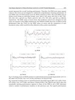
presented in figures (1.8) to (1.15) while the robot walks over declined surfaces for the
single phase of the walking. Figure (1.15) shows combined path of the robot. The used
specifications of the simulation of the robot are listed in table No. 1. Figures (1.8),
(1.10) and (1.12) display the moving type of ZMP with the nominal walking of the
robot. Figures (1.9), (1.11) and (1.13) show the same type of ZMP and also the un-
nominal walking of the robot (with the changed hip height form the fixed coordinate
system). Figure (1.14) shows the fixed ZMP upon descending surface. As can been seen
from the table, the swing and support legs have the same geometrical and inertial
values whereas in the designed program the users can choose different specifications.
Note, the swing leg impact and the ground has been regarded in the designed program
as given in references [Lum and et. Al. 1999 and Westervelt, 2003, and Hon and et. Al.,
1978]. Below, the saggital movement and stability analysis of the seven link biped
robot has been considered whereas the frontal considerations are neglected. For
convenience, 3D simulations of the biped robot are presented. In table No. 1,
aban
ll ,
and
af
l present the foot profile which are displayed in figure (1.7). The program
enables the user to compare the results as presented in figures where the paths for the
single phase walking of the robot have been concerned. In the program with the aid of
the given break points, either third-order spline or Vandermonde Matrix has been
used for providing the different trajectory paths. With the aid of the designed
program, the kinematic, dynamic and control parameters have been evaluated. Also,
Humanoid Robots, New Developments108
the two types of ZMP have been investigated. The presented simulations indicate the
hip height effects over joint’s actuator torques for minimizing energy consumption and
especially obtaining fine stability margin. As can be seen in figures (9.h), (11.h) and
(13.h), for the un-nominal walking of the robot with the lower hip height, the knee's
actuator torque values is more than the obtained values as shown in figures (8.h),
(10.h) and (12.h) (for the nominal gait with the higher hip height). This is due to the
robot's need to bend its knee joint more at a low hip position. Therefore, the large knee
joint torque is required to support the robot. Therefore, for reducing the load on the
knee joint and consequently with respect to minimum energy consumption, it is
essential to keep the hip at a high position. Finally, the trajectory path generation
needs more precision with respect to the obtained kinematic relations to avoid the
link’s velocity discontinuities. The presented results have an acceptable consistency
with the typical robot.
.Sh
l
Ti
l
.To
l
an
l
ab
l
af
l
m3.0 m3.0 m3.0 m1.0 m1.0 m13.0
.Sh
m
.Th
m
.To
m
.Fo
m
s
D
c
T
kg7.5 kg10 kg43 kg3.3
m5.0 s9.0
d
T
m
T
ao
H
ao
L
ed
x
sd
x
s18.0 s4.0 m16.0 m4.0 m23.0 m23.0
gs
g
gf
g
min
H
max
H
s
h
s
H
00 m60.0 m62.0 m1.0 m15.0
shank
I
tight
I
torso
I
foot
I
2
02.0 kgm
2
08.0 kgm
2
4.1 kgm
2
01.0 kgm
Table 1. The simulated robot specifications.
Fig. 1.7. The foot configuration.
an
l
af
l
ab
l
Dynamic Simulation of Single and Combined Trajectory Path Generation and
Control of A Seven Link Biped Robot 109
(a) Stick Diagram (b) ZMP
(c) Velocity (d) Acceleration (e) Angular Vel. (f) Angular Acc.
(j) Inertial Forces (h) Driver Torques
Fig. 1.8. (a) The robot’s stick diagram on
$
0
O
, Moving ZMP,
mHmH 62.0,60.0
maxmin
(b) The moving ZMP diagram in nominal gait which satisfies stability criteria (c) __: Shank M.C
velocity, : Tight M.C velocity (d)__: Shank M.C acceleration, :Tight M.C acceleration (e) __:
Shank angular velocity, : Tight angular velocity (f) __: Shank angular acceleration, : Tight
angular acceleration (j) __: Shank M.C inertial force, : Tight M.C inertial force (h) __: Ankle joint
torque, : Hip joint torque, …: Shank joint torque
Humanoid Robots, New Developments110
(a) Stick Daigram (b) ZMP
(c) Velocity (d) Acceleration (e) Angular Vel. (f) Angular Acc.
(j) Inertial Forces (h) Driver Torques
Fig. 1.9. (a) The robot’s stick diagram on
$
0
O
, Moving ZMP,
mHmH 52.0,50.0
maxmin
(b) The moving ZMP diagram in nominal gait which satisfies stability criteria (c) __: Shank M.C
velocity, : Tight M.C velocity (d)__: Shank M.C acceleration, :Tight M.C acceleration (e) __:
Shank angular velocity, : Tight angular velocity (f) __: Shank angular acceleration, : Tight
angular acceleration (j) __: Shank M.C inertial force, : Tight M.C inertial force (h) __: Ankle joint
torque, : Hip joint torque, …: Shank joint torque
Dynamic Simulation of Single and Combined Trajectory Path Generation and
Control of A Seven Link Biped Robot 111
(a) Stick Diagram (b) ZMP
(c) Velocity (d) Acceleration (e) Angular Vel. (f) Angular Acc.
(j) Inertial Forces (h) Driver Torques
Fig. 1.10 (a) The robot’s stick diagram on
$
10
O
, Moving ZMP,
mHmH 62.0,60.0
maxmin
(b) The moving ZMP diagram in nominal gait which satisfies stability criteria (c) __: Shank M.C
velocity, : Tight M.C velocity (d)__: Shank M.C acceleration, :Tight M.C acceleration (e) __:
Shank angular velocity, : Tight angular velocity (f) __: Shank angular acceleration, : Tight
angular acceleration (j) __: Shank M.C inertial force, : Tight M.C inertial force (h) __: Ankle joint
torque, : Hip joint torque, …: Shank joint torque
Humanoid Robots, New Developments112
(a) Stick Diagram
(b) ZMP
(c) Velocity (d) Acceleration
Dynamic Simulation of Single and Combined Trajectory Path Generation and
Control of A Seven Link Biped Robot 113
(e) Angular Vel. (f) Angular Acc.
(j) Inertial Forces (h) Driver Torques
Fig. 1.11.
(a) The robot’s stick diagram on
$
10
O
, Moving ZMP,
mHmH 52.0,50.0
maxmin
(b) The moving ZMP diagram in nominal gait which satisfies stability criteria
(c) __: Shank M.C velocity, : Tight M.C velocity
(d)__: Shank M.C acceleration, :Tight M.C acceleration
(e) __: Shank angular velocity, : Tight angular velocity
(f) __: Shank angular acceleration, : Tight angular acceleration
(j) __: Shank M.C inertial force, : Tight M.C inertial force
(h) __: Ankle joint torque, : Hip joint torque, …: Shank joint torque
Humanoid Robots, New Developments114
(a) Stick Diagram
(b) ZMP
(c) Velocity (d) Acceleration
Dynamic Simulation of Single and Combined Trajectory Path Generation and
Control of A Seven Link Biped Robot 115
(e) Angular Vel. (f) Angular Acc.
(j) Inertial Forces (h) Driver Torques
Fig. 1.12.
(a) The robot’s stick diagram on
$
8
O
, Moving ZMP,
mHmH 62.0,60.0
maxmin
(b) The moving ZMP diagram in nominal gait which satisfies stability criteria
(c) __: Shank M.C velocity, : Tight M.C velocity
(d)__: Shank M.C acceleration, :Tight M.C acceleration
(e) __: Shank angular velocity, : Tight angular velocity
(f) __: Shank angular acceleration, : Tight angular acceleration
(j) __: Shank M.C inertial force, : Tight M.C inertial force
(h) __: Ankle joint torque, : Hip joint torque, …: Shank joint torque
Humanoid Robots, New Developments116
(a) Stick Diagram
(b) ZMP
(c) Velocity (d) Acceleration
Dynamic Simulation of Single and Combined Trajectory Path Generation and
Control of A Seven Link Biped Robot 117
(e) Angular Vel. (f) Angular Acc.
(j) Inertial Forces (h) Driver Torques
Fig. 1.13
(a) The robot’s stick diagram on
$
8
O
, Moving ZMP,
mHmH 52.0,50.0
maxmin
(b) The moving ZMP diagram in nominal gait which satisfies stability criteria
(c) __: Shank M.C velocity, : Tight M.C velocity
(d)__: Shank M.C acceleration, :Tight M.C acceleration
(e) __: Shank angular velocity, : Tight angular velocity
(f) __: Shank angular acceleration, : Tight angular acceleration
(j) __: Shank M.C inertial force, : Tight M.C inertial force
(h) __: Ankle joint torque, : Hip joint torque, …: Shank joint torque
Humanoid Robots, New Developments118
(a) Stick Diagram
(b) ZMP
(c) Velocity (d) Acceleration
Dynamic Simulation of Single and Combined Trajectory Path Generation and
Control of A Seven Link Biped Robot 119
e) Angular Vel. (f) Angular Acc.
(j) Inertial Forces (h) Driver Torques
Fig. 1.14
(a) The robot’s stick diagram on
$
8
O
, Fixed ZMP,
mHmH 62.0,60.0
maxmin
(b) The fixed ZMP diagram in nominal gait which satisfies stability criteria
(c) __: Shank M.C velocity, : Tight M.C velocity
(d)__: Shank M.C acceleration, :Tight M.C acceleration
(e) __: Shank angular velocity, : Tight angular velocity
(f) __: Shank angular acceleration, : Tight angular acceleration
(j) __: Shank M.C inertial force, : Tight M.C inertial force
(h) __: Ankle joint torque, : Hip joint torque, …: Shank joint torque
Humanoid Robots, New Developments120
(a) Stick Diagram (b) ZMP (c) Inertial Forces
(d) Driver Torques (e) Driver Torques
Fig. 1.15 (a) The robot’s stick diagram on combined surface, nominal motion, Moving ZMP,
8
O
$
(b) The moving ZMP diagram in nominal gait which satisfies stability criteria (c) Inertial
forces: __: Supp. tight, : Supp. shank, …: Swing tight, : Swing shank (d) Joint’s torques: __: Swing
shank joint, : Swing ankle joint, …: Supp. hip joint, : Swing hip joint (e) Joint’s torques: __: Supp.
ankle joint, : Supp. shank joint
5. References
Peiman Naseradin Mousavi, Ahmad Bagheri, “Mathematical Simulation of a Seven Link Biped Robot
and ZMP Considerations”, Applied Mathematical Modelling, Elsevier, 2007, Vol. 31/1.
Q. Huang, K. Yokoi, S. Kajita, K. Kaneko, H. Arai, N. Koyachi, K. Tanie, “Planning Walking
Patterns For A Biped Robot”, IEEE Transactions on Robotics and Automation, VOL
17, No. 3, June 2001.
John J. G, “Introduction to Robotics: Mechanics and Control”, Addison-Wesley, 1989.
H. K. Lum, M. Zribi, Y. C. Soh, “ Planning and Contact of a Biped Robot”, International
Journal of Engineering Science 37(1999), pp. 1319-1349
Eric R. Westervelt, “ Toward a Coherent Framework for the Control of Plannar Biped
Locomotion”, A dissertation submitted in partial fulfillment of the requirements
for the degree of Doctor of Philosophy, (Electrical Engineering Systems), In the
University of Michigan, 2003.
H. Hon, T. Kim, and T.Park, “Tolerance Analysis of a Spur Gear Train,” in Proc. 3
rd
DADS
Korean user’s Conf. 1978, pp. 61-81
Peiman Naseradin. Mousavi, “Adaptive Control of 5 DOF Biped Robot Moving On A
Declined Surface”, M.S Thesis, Guilan University, 2006.
A. Bagheri, M.E. Felezi, P. N. Mousavi, “ Adaptivr Control and Simulation of a Seven Link
Biped Robot for the Combined Trajectory Motion and Stability Investigations”,
WSEAS Transactions on Systems, Issue 5, Vol. 5, May 2006, pp: 1214-1222
A. Bagheri. F. Najafi, R. Farrokhi, R. Y. Moghaddam, and M. E. Felezi, “Design, Dynamic
Modification, and Adaptive Control of a New Biped Walking Robot”, International
Journal of Humanoid Robotics, Vol. 3, Num.1, March 2006, pp 105-126
7
Analytical Criterions for the Generation of
Highly Dynamic Gaits for Humanoid Robots:
Dynamic Propulsion Criterion and
Dynamic Propulsion Potential
Olivier Bruneau
Université de Versailles Saint-Quentin-en-Yvelines,
Laboratoire d’Ingénierie des Systèmes de Versailles (LISV, EA 4048)
France
Anthony David
Université d’Orléans, Ecole Nationale Supérieure d’Ingénieurs de Bourges,
Laboratoire Vision et Robotique (LVR, EA 2078)
France
1. Introduction
Many studies have been made to develop walking anthropomorphic robots able to move in
environments well-adapted to human beings and able to cooperate with them. Among the
more advanced projects of humanoid robots, one can mention : the Honda robots P2, P3
(Hirai, 1997) (Hirai et al., 1998) and Asimo (Sakagami et al., 2002), the HRP series developed
by AIST (Kaneko et al., 1998) (Kajita et al., 2005) (Kaneko et al., 2004) (Morisawa et al., 2005),
the small robot QRIO proposed by Sony (Nagasaka et al., 2004), the KHR series developed
by KAIST (Kim et al., 2004) (Kim et al., 2005), the last robot of Waseda University having
seven degrees of freedom per leg (Ogura et al., 2004), Johnnie (Lohmeier et al., 2004) and H7
(Kagami et al., 2005). These robots are namely able to climb stairs and to carry their own
power supply during stable walking. The problem of dynamic locomotion and gait
generation for biped robot has been studied theoretically and experimentally with quite
different approaches. However, when searchers study the behavior or the design of
dynamic walking robots, they inevitably meet a number of intrinsic difficulties related to
these kinds of systems : a large number of parameters have to be optimized during the
design process or have to be controlled during the locomotion task; the intrinsic stability of
walking machines with dynamic behaviors is not robust; the coordination of the legs is a
complex task. When human walks, it actively uses its own dynamic effects to ensure its
propulsion. Today, some studies exploit the dynamic effects to generate walking gaits of
robots. In this research field, four kinds of approaches are used. The first one uses pragmatic
rules based on qualitative studies of human walking gaits (Pratt et al., 2001) (Sabourin et al.,
2004). The second one focuses on the mechanical design of the robot in order to obtain
natural passive dynamic gaits (Collins et al., 2005). The third one deals with theoretical