Illustrated Sourcebook of Mechanical Components Part 2 potx
Bạn đang xem bản rút gọn của tài liệu. Xem và tải ngay bản đầy đủ của tài liệu tại đây (3.05 MB, 45 trang )
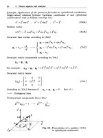
1-54
6
Ways
to Prevent Overloading
These "safety valves" give way
if
machinery jams, thus preventing serious damage.
Peter C.
Noy
r
Fricfion
faces
Sprocket
3
m
tl
1
SHEAR PIN
is simple to design and reliable in service.
However, after
an
overload, replacing the pin takes
a
rela-
tively long time; and new pins aren't always available.
3
MECHANICAL
KEYS.
Spring holds ball in dimple
in
oppo-'
site
Pace
until overload forces the ball out. Once
slip
begins,
wear
is
rapid,
BO
device
is
poor
when overload
is
common.
2
FRICTION CLUTCH.
Adjustable spring tension
that
holds
the two friction surfaces together sets overload limit.
As
soon
as
overload
is
removed the clutch reengages.
One
drawback
is
that
a
slipping clutch can destroy
itself
if
unnoticed.
Adjustment
screw
Gears
&
Gearing
1-55
r-i
01'
I
4
RETRACTING KEY.
Ramped sides
of
keyway force key outward against adjust-
abe spring. As key moves outward,
a
rubber pad-or another spring-forces the
key into
a
slot in the sheave. This holds the key out
of
engagement and prevents
wear.
To
reset, push key out
of
slot by using hole in sheave.
Load
b
5
ANGLE-CUT CYLINDER.
With
just
one tooth, this is
a
sim-
plified version
of
the jaw clutch. Spring tension
sets
load limit.
6
DISENGAGING
GEARS.
Axial forces
of
spring and driving
arm balance. Overload overcomes spring force to slide
gears out
of
engagement. Gears can strip once overloading
is
removed, unless
a
stop
holds
gears out
of
engagement.
1-56
Torque-lim iters Protect
light-Duty Drives
In such drives the light parts break easily when overloaded.
These eight devices disconnect them from dangerous torque surges.
L.
Kasper
1
2
MAGNETS
transmit toraue according to their number and size.
CONE CLUTCH
is
formed
by
mating
taper
on
In-place control is limited to lowering torque capacity by remov-
ing magnets. down on nut increases torque capacity.
shaft
to
beveled hole through gear. Tightening
3
RING
fights natural tendency of rollers to jump
out
of
grooves cut in reduced end
of
one shaft.
Slotted eiitl
of
hollow
shaft,
is
like
a
cage.
Gears
&
Gearing
1-57
4
5
ARMS
hold rollers in slots which are cut across disks
mounted on ends
of
butting shafts. Springs keep rollers
in
slots: over-torque forces them
out.
FLEXIBLE
BELT
wrapped around four pins transmits
only lightest loads. Outer pins are smaller than inner
pins
to
ensure contact.
possoje
6
7
SPRINGS
inside drilled block grip the shaft because
SLIDING WEDGES
clamp down on flattened end
of
they distort during mounting
of
gear.
shaft: spread apart when torque gets too high. Strength
of
springs which hold wedges together sets torque limit.
8
FRICTION
DISKS
are compressed by adjustable spring.
Square disks lock into square hole in left shaft:
round
ones lock onto square rod on right shaft.
I
L
LU
S
T
RAT
E
D
S
0
U
RC
E
B
0 0
K
of
ME
C
HAN
I
CAL
C
0
M
P
0
N
E
N
T
S
SECTION
2
HAINS,
SPROCKETS
WTCHETS
History of Chains
Ingenious Jobs for Roller Chain
Bead Chains for Light Service
Types of Trolley Convey or Chain Links and Joints
Method for Reducing Pulsations in Chain Drives
Pave the Way for Better Chain Drives
Lubrication of Roller Chains
One-way Drive Chain Solves Problem of Sprocket Skip
Chain Hoist for Dam’s Radial Arm Gate
Portable Chain Hoist for Motors
Design of Precision Sprockets
Sheet Metal Gears, Sprockets, Worms
&
Ratchets
Ratchet Layout Analyzed
No
Teeth Ratchets
2-2
2-4
2-8
2-10
2-12
2-14
2-15
2-17
2-18
2-19
2-20
2-23
2-25
2-27
Chains,
Sprockets
&
Ratchets
2-3
There are eighteen American National Standards which relate
to
the various
types of sprocket chains in general use. This family of standards is the result
of
over
50
years of standardization activity, which had its beginning in the work
that led
to
the publication of
American Standard B29a-Roller Chain. Smock-
ets, and Cutters
in
as
follows:
ANSI
B29.1
ANSI
B29.2
ANSI
B29.3
ANSI
B29.4
ANSI
B29.6
ANSI
B29.7
ANSI
B29.8
ANSI
B29.10
ANSI
B29.11
ANSI
B29.12
ANSI
B29.14
ANSI
B29.15
ANSI
B29.16
ANSI
B29.17
ANSI
B29.18
ANSI
B29.19
ANSI
B29.21
ANSI
B29.22
I1
1930.
The chain types covered by the current standards are
Precision roller chain
Inverted-tooth (or silent) chain
Double-pitch roller chain for power transmission
Double-pitch roller chain for conveyor usage
Steel detachable chain
Malleable iron detachable chain
Leaf chain
Heavy-duty offset-sidebar roller chain
Combination chain
Steel-bushed rollerless chain
Mill chain
(H
type)
Heavy-duty roller-type conveyor chain
Mill chain (welded type)
Hinge-type flat-top conveyor chain
Drag chain (welded type)
Agricultural roller chain
(A
and
CA
types)
Chains for water and sewage treatment plants
Drop-forged rivetless chain
The basic size dimension for
all
types of chain is pitch-the center-to-center
distance between two consecutive joints. This dimension ranges from
3/16
in (in
the smallest inverted-tooth chain)
to
30
in (the largest heavy-duty roller-type
conveyor chain).
Chains and sprockets interact with each other
to
convert linear motion
to
rotary
motion or vice versa, since the chain moves in an essentially straight
line between sprockets and moves in
a
circular path while engaged with each
sprocket.
A
number of tooth-form designs have evolved over the years, but the
prerequisite of any tooth form
is
that it must provide:
1.
Smooth engagement and disengagement with the moving chain
2.
Distribution of the transmitted load over more than one tooth of the
sprocket
3.
Accommodation of changes in chain length
as
the chain elongates as a
result of wear during its service life
The sprocket layout is based on the pitch circle, the diameter of which is
such that the circle would pass through the center of each of the chain's joints
when that joint is engaged with the sprocket. Since each chain link is rigid, the
engaged chain forms
a
polygon whose sides are equal in length
to
the chain's
pitch. The pitch circle of a sprocket, then, is
a
circle that passes through each
comer, or vertex, of the pitch polygon. The calculation of the pitch diameter of
a
sprocket follows the basic rules of geometry as they apply to pitch and
number of teeth. This relationship is simply
pitch
pitch
diameter
=
sin (180"humber of teeth)
The action of the moving chain as it engages with the rotating sprocket is
one of consecutive engagement. Each link must articulate,
or
swing, through a
specific angle to accommodate itself
to
the pitch polygon, and each link must
be completely engaged, or seated, before the next in succession can begin its
articulation.
Source. Mechanical Components
Handbook
by
Robert
0.
Parmley
01985
Chains, Sprockets
&
Ratchets
2-5
4
TRANSMISSION
OF
TIPPING OR ROCKING MOTION.
Can be combined with previous example
(3)
to transmit
this type
of
motion to a remote location and around
obstructions. Tipping angle should not exceed
40"
approx.
5
LIFTING DEVICE
is
simplified
by
roller chain.
Chain
mainfains
inward pressure
on
boards
fhrough
slip
clulch
j
TWO
EXAMPLES
OF
INDEXING AND FEEDING
uses
of
roller chain are shown here in a setup that feeds
plywood
strips
into
EL
brush-making machine.
Advantages
of
roller chain
as
used here are flexibility and long feed.
2-6
Examples
of
how this low-cost but precision-made product can be
arranged to do
tasks
other that transmit power.
7
SIMPLE GOVERNOR-weights can be attached
by
means of standard brackets to increase responze
force when rotation speed
is
slow.
A
I
Ao)ustrnenf
boles
6
Force
8
WRENCH-pivot A can be adjusted
to
grip a va-
riety
of
regularly
or
irregularly shaped objects.
Sprocket
9SMALL PARTS CAN
BE
CONVEYED, fed,
or
oriented
between spaces
of
roller chain.
Chains, Sprockets
&
Ratchets
2-7
11
LIGHT-DUTY
TROLLEY
CONVEYORS
can be made by
combining standard roller-
chain components with stand-
ard curtain-track components.
Small gearmotors are
used
to drive the conveyor.
10
CLAMP-toggle action
is
sup-
plied by
two
chains, thus
clearing pin at fulcrum.
Sfondam'
offochmenf
frock
I-beom
frock
fro//eys
Roller
lor
/odderl
chain
I
Conveyor
hook
12
SLATTED
BELT,
made
by
attach-
ing wood, plastic
or
metal slats,
can serve as adjustable safety
guard, conveyor belt, fast-acting
security-wicket window.
Chains, Sprockets
&
Ratchets
Where torque requirements and operating speeds are low, qualified bead chains
offer a quick and economical way to: Couple misaligned shafts; convert from one type
of
motion to another: counter-rotate shafts: obtain
high
ratio drives and overload
protection: control switches and serve as mechanical counters.
Fig. 8-Angular oscillations from
ro-
Fig. 9-Restricted angular motion. Fig. 10-Remote control of counter.
tary
input. Link makes complete revo-
Pulley, rotated by knob, slips when For applications where counter can-
lutions causing sprocket to oscillate.
limit stop
is
reached; shafts
A
and
B
not be coupled directly to shaft, bead
Spring maintains chain tension. remain stationary and synchronous. chain and sprockets can be used.
Aoose
chain
Fig. 11-High-ratio
drive
less
Fig. 12-Timing chain containing large Fig. 13-4onveyor belt composed
of
expensive than gear
trains.
beads at desired intervals operates micro- multiple chains and sprockets. Tension
Qualified bead chains and switch. Chain can be lengthened to contain maintained by pivot bar and spring.
sprockets
will
traasmit power
without slippage.
thousands of intervals for complex timing.
Width
of
belt easily changed.
ft
L.
-
1
Fig. 144ear and rack
duplicated
by
chain and
two
sprockets. Converts linear
motion into rotary motton.
,Idler
Pig.
15
-
Overload protection.
Shallow sprocket gives positive
drive
for
low loads; slips one
head
at
a
time when overloaded.
Sprockef
wiYh
sha/fowJ
recesses
Fig. 16-Gear segment inexpensively
made with bead chain and spring
wrapped around edge
of
sheet metal.
Retaining collars keep sheet metal
sector from twisting
on
the shaft.
2-9
Chains, Sprockets
&
Ratchets
29-
1
1
THE
SUCCESS
of the overhead trolley conveyor
is
largely the result of the development and
use
of drop-
forged, rivetless, Keystone chain. The dimensions of
several sizes of Keystone chain links are shown below
with
two
examples of pin-jointed chain. Standard
Keystone chain
parts
are shown
in
three views.
DETAILS FOR PARTS OF STANDARD
KEYSTONE
CHAIN
(-3j
;;;$"
Pin
Standard
Center
Link
i:
I
I
drrrrr
6.
Webb
Ca
I
Standard
Side
Link
I
I
PIN- JOINTED
LINKS
C-188
Chain
C-131
Chain
DIMENSIONS
OF
KEYSTONE LINKS
I
I
I
~-;n.~;~~ ~ 6-in.~ifc~ ~,
I+
678
Chain
I
/+
,#,A
p,,ch
&
-
4jn,
p,fch
I
458
Chain-Standard Center
Link
458
Chain-Modified Center
Link
An
Improved
Type.
Interchangeable with
450
Chain
Coupler
Pins
for
Keystone Choin
346
Chain
Modified
Center
Link
Chains, Sprockets
&
Ratchets
fnpu
1
Reduction gears
*
Choin
sprocket’,r
actuated lever and rollers
8
take up slack. Conveyor motion
is
equalized but mechanism has limited power capacity be-
cause pitch
of
chain
l
must be kept small. Capacity can
be increased by using multiple strands
of
fine-pitch chain.
-
1
(input
shot
tl
Fig. &Power is transmitted from shaft
2
to sprocket
G
through chain
4,
thus imparting a variable velocity to
shaft
3,
and through it, to the conveyor sprocket
7.
Since
chain
4
has small pitch and sprocket
5
is relatively large,
velocity
of
4
is almost constant which induces an almost
constant conveyor velocity. Mechanism requires rollers to
tighten slack side
of
chain and has limited power capacity.
=-=
n
,
Sprocket
Fig. 5-Variable motion to sprocket is produced by disk
3
which supports pin and roller
4,
and disk
5
which has a
radial slot and is eccentrically mounted on shaft
2.
Ratio
Fig.
6
.
of
rpm
of
shaft
2
to sprocket equals number of teeth in
sprocket. Chain velocity is not completely equalized.
/-
7.
’
-
______-
,’
,
‘.,
‘\
Fig. &Integrated “planetary gear” system (gears
4,
5,
G
and
7)
is activated by cam
10
and transmits through shaft
2
a variable velocity to sprocket synchronized with chain
pulsations thus completely equalizing chain velocity. The
cam
10
rides
on
a
circular idler roller
11;
because of the
equilibrium of the forces the cam maintains positive contact
with the roller. Unit uses standard gears, acts simultaneously
as
a speed reducer, and can transmit high horsepower.
\
\
\
2-13
2-16
Pitch
of
chain,
in.
M-N
%-I
x
12i-p
Unsatisfactory chain life
is
usually +he resulf
of
poor or ineffective lubrication. More
damage
is
caused by faulty lubrication than by years of normal service. illustrated
below are
9
methods for lubricating roller chains. Selection should be made on basis
of
chain speed as shown in Table
1.
Recommended lubricants are listed in Table
II.
Viscosity at
100
F,
SUS
24l3-420
420-620
620-1300
Table
I-Recommended Methods
0-600
600-1500
over
1500
Table
II-Recommended Lubricants
Manual:
brush,
oil
can
Slow
Drip:
4-10
drops,min
Continuous: wick, wheel
Rapid
Drip-20
drops, min
Shallow Bath,
Disk
Force Feed Svstems
I
[ChgTrid,
Method
Note:
For
ambient temperatures between
100
to
500
Fuse
SAE
50.
Pig. 8-FORCE-FEED LUBRICATION
for
chains running at extremely high speeds.
Pump driven by motor delivers
oil
under
pressure
to
nozzles that direct spray on to
chain, Excess oil collects in reservoir which
has
wide
area to cool oil.
SAE
No.
Fig. CHALLOW
BATH
LUBRICATION uses casing as
reservoir
for
oil. Lower part
of
chain just skims
through
oil
pool. Levels
of
oil must be kept tangent to chain sprocket
to avoid excessive churning. Should not be
used
at high
speeds because
of
tendency to generate excessive heat.
Disk
Sprocket,
.
Fig.
7
&servoir
20
30
40
Fig. 7-DISK
OR
SLINGER can be attached to
lower sprocket to give contiuoous supply
of
oil.
Disk scoops up
oil
from reservoir and throws it
against baffle, Gutter catches 011 dripping
down
from baffle and directs it
on
to chain.
Chain
r
-Flow
control
valve
-
-
Excess
oil
-
-Oil
reservoir
Inlet
Fig.
9
Fig. %CHAIN-DRIVEN FORCE-FEED system has pump driven
by main drive shaft. Flow control valve, regulated
from
outride
of casing, by-passes excess oil back to reservoir. Inlet
hose
contams
filter. Oil should be changed periodically-espedally when hue
is
brown instead
of
black.
Chains,
Sprockets
&
Ratchets
2-2
1
diameter of the sprocket the tooth form will clear
the perforations in the film while the film is being
loaded or unloaded tangent to the roll diameter.
To
help determine the correct pressure angle, it
is
necessary to establish how many degrees
of
rota-
tion on the sprocket are needed
to
satisfy an epicy-
cloid profile tooth. This information can be
established as follows (See Fig. 5) and these com-
puations:
R,-Outside radii
of
sprocket teeth, 1.7146 in.
r
-Mean radii of the film rolled on 1-in. dia roll-
C
-Center distance between the sprocket and
R
-Mean radii of film rolled
on
roll diameter of
er, 0.503 in.
roller with film in between, 2.1697 in.
sprocket,
cos
0
=
O=
-
-
O=
cos
9
=
- -
9=
1.6667 in.
r2
+
C2
-
R,2
2rC
0.5032
+
2.169P
-
1.7146'
2
x
0.503
x
2.1697
0.92567
22.2302"
1.71462
+
2.1697'
-
0.5032
2
X
2.1697
X
1.7146
0.99382
6.37202", or 0.1112 radians
Because the roller
r
rolls on the radius
R
and does
not slip, they both
rQll
off
an equal amount of their
circumference. Therefore, their arcs
AB
and
BD
are
equal. Employing the theorem-radius multiplied by
the included angle expressed in radians equals the
length
of
arc in the included angle; then because the
two arcs are equal to each other, their equations are
also equal to each other.
Or
8s
=xr=-R
180
Orr
180
Or
.*.
8
=-
x-
-
-
-
180
R
K
R
22.2301
X
0.503
1.667
a=
=
6.709",
or
0.1171
radians
+E
=
8
-
=
0.0059 radians
It is important to make certain that the pressure
angle
of
the teeth at the outside diameter of the
sprocket when generated is an involute greater than
14"47', which would be the pressure angle of an in-
volute tooth whose involute function is equal to
+E.
Because the pitch diameter
of
the gear in the follow-
FIG.
5
l
ing computations is just about equal to the outside
diameter of the sprocket, a pressure angle of 15"
3%'
is
selected because the base circle for this gear
would then fall approximately 0.011 in. below the
roll diameter. Furthermore, by providing a mini-
mum radius
of
0.004 in.
on
the wheel, the sprocket
tooth will not be undercut.
This data is now converted into information
similar to gear calculations in order to setup the
Reishauer gear grinder, or any other gear-generat-
ing machine tool. From the Reishauer manual
PZA
75 a gear train can be setup as follows:
G3
12
-
GI
DP
G2
G4
x-
-
From the selection of change gears a
16
1/3
DP
is
easily obtained.
12
40 54
DP
70
-
42
-
.'.
DP
=
16
1/3
2-22
Computing the imaginary gear
No.
of teeth
Diametral Pitch
Pressure angle
Pitch diameter
Circular pitch
Outside diameter
Whole depth
Root diameter
D,
=
=
3.4286
N
N
=
56
P
=
16 1/3
+2
=
15"
3%'
D:,
=
3.4286
C
=
-
=
0.1923
?r
P
D
2.156
P
=
0.132
- -
RD
=
3.2870
Base dia.
=
0.9915
x
3.3333
=
3.3048
Referring to Fig.
3,
the sprocket tooth shows a
height of 0.051 in. and an undercut of
0.10
in. below
roll diameter. Therefore, the wheel will penetrate
0.061
in. below the outside diameter of the sprocket.
Also note that the tooth has a chordal thickness of
0.055 in. at the roll diameter. The arc tooth thick-
ness
is
0.055 in. at the point
of
contact with the mean
thickness
of
the film. However, for the purpose of
dimensioning the grinding wheel the arc tooth thick-
ness must be determined at the pitch diameter of the
imaginary gear.
LGrinding wheel
FIG.
7
T,
=
Arc tooth thickness of tooth at
D,
=
0.055
T,
=
Arc tooth thickness of tooth at
D,
=
Pressure angle at point where the mean
diameter of the film makes contact with
the tooth
D,
=
mean dia of film
=
3.3333
D,
=
pitch dia
=
3.4286
COS
+z
=
15"31/i'
G
0.9639
D
COS
$2
3.4286
x
0.9639
cos
+1
=
3
-
-
-
-
=
0.99145
D,
-
3.3333
41
=
7"30'
Inv
+1
=
0.00075
Inv
+2
=
0.00622
1
x
Inv
-
Inv
#,z
1
0.055
T,
=
3.4286[-+
0.00075
-
0.00622
=
0.0343
The root diameter of the sprocket is equal to the
roll diameter minus
0.020
in. as indicated in Fig.
3,
or
3.3073
in. This figure is
0.1213
in. less than the
pitch dia of the imaginary gear. Therefore, to deter-
mine the dimension for the width of the groove in the
grinding wheel at the point of deepest penetration,
Fig.
7,
multiply
0.1213
in. by the tangent of
+z
and
add this value to
T,.
ie:
0.26904
x
0.1213
+
0.0343
=
0.067
in.
From this information the grinding wheel can
now be dimensioned.
It should be noted that the dimensions given in
Fig.
7
are normal to the tooth and not parallel to
axis of wheel.
.i
/
FIG.
a
I
2-24
Fig. 10-Sheet metal
cup
which Fig. 11-Blanked wheel, with Fig. 12-Worm wheel is sheet metal
has indentations that take place
blanked, with specially formed teeth.
of worm wheel teeth, meshes with
Worm is made
of
sheet metal disk,
a standard coarse thread screw.
split and helically formed.
specially formed teeth, meshes
with
a
helical spring mounted on
a shaft, which serms
as
the worm.
Fig. 13-Blanked ratchets with one sided teeth stacked to
fit
a wide, sheet metal finger when single thickness is not
adequate. Ratchet gears can
be
spot welded.
Fig.
14-To
avoid stacking, single ratchet is used with a
U-shaped finger also made
of
sheet metal.
Fig. 15-Wheel is
a
punched disk with square punched
holes to selve as teeth. Pawl is spring steel.
Fig.
17
Pig. 16-Sheet metal blanked pinion,
with specially formed teeth, meshes
with windows blanked in
a
sheet metal
cylinder, to form a pinion and rack
assembly.
Fig. 1i’-Sprocket, like Fig. 13, can be fabricated from separate stampings.
Fig. l&For
a
wire chain as shown, sprocket is made by bending out
punched teeth on a drawn
cup.
2-26
Pawl
in
tension
. . .
has same forces acting on
unit
as other
arrangements. Same layout principles
apply also.
For
steel on steel, dry,
p
=
0.15.
Therefore, using
r/R
=
0.20
to
0.25
the margin
of
safety
is
large; the pawl will slidc into
engagement easily.
For
internal teeth with
4
of
30°,
c/b is tan
30"
or
0.577 which is larger than
p,
and
the teeth are therefore
self
engaging.
When laying out the ratchet wheel and pawl, locatc
points
0,
A
and
0,
on
the samc circle.
A0
and
AO,
will then
be
perpendicular to onc another; this will
insure that the smallest forces are acting on the systcm.
Ratchet and pawl dimensions are governed by design
sizes and stress. If the tooth, and thus pitch, must bc
larger than
required
in order to be strong enough.
a
multiple pawl arrangcmcnt can be used.
The
pawls
can be arranged
so
that one
of
them will cngage thc
ratchet after
a
rotation of
less
than the pitch.
A
fine feed can be obtained by placing a numbcr
of pawls sidc by sidc, with thc corrcspoiicling Ih3ict
whccls uniformly displaced and interconnectcd.
2-28
6
Eccenfric
__
corn
c
E/ongofed
-
hole
4
ECCENTRIC ROLLERS
squeeze disk on
forward stroke. On return stroke, rollers
rotate backwards and release their grip.
Springs keep rollers in contact with disk.
5
RACK
is wedge-shape
so
that it janis be-
tween the rolling gear and the disk, push-
ing the shaft forward. When the driving
lever makes its return stroke, it carries
along the unattached rack by the cross-
piece.
6
CONICAL PLATE
moves
as
a
nut back
and forth along the threaded center hub
of the lever. Light friction
of
spring-
loaded pins keeps the pIate from rotating
with the hub.
7
FLAT SPRINGS
expand against inside of
drum when lever moves one way, but
drag
loosely when lever turns drum in
opposite direction.
8
ECCENTRIC CAM
jams against disk
during motion half of cycle. Elongated
holes in the levers allow cam to wedge
itself inore tightly in place.
I
L
LU
S
T
RAT
E
D
S
0
U
RC
E
B
0
0
K
of
M
E
C
H
AN
I
CAL C
0
M
P
0
N
E
NT
S
SECTION
3
BELTS
Unique Belt Applications 3-2
Leather Belts-Hp Loss and Speed
3-1
1
Find the length of Open and Closed Belts
3-12
Ten Types of Belt Drives
3-14
Mechanisms for Adjusting Tension of Belt Drives
3-16
Equations for Computing Creep in Belt Drives
3-18
Typical Feeders, Take-ups, Drives and Idlers for Belt Conveyors 3-22
Belts
&
Belting
3-3
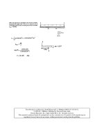
While the supercharger drive, racing application is highly visible and glamorous, the same
polyurethane belt is used in industry to replace roller chain on a wide variety of applications.
Roller chain requires lubrication and regular maintenance in order to perform at its peak level.
Roller chain can stretch up to
3%
of
its length over the life of the chain. The Kigh capacity,
polyurethane synchronous belt provides superior horsepower capacity, with virtually no stretch.
Relative Center Distance
Take-up
Required
(100”
Chain
/
Poly
Chain
GT)
.04
I
PolPcb.i.GT)P
I
I
I
I
I I I
I
Stretch comparison of high performance polyurethane synchronous belt vs. roller chain.
Over time, stretch of flexible power transmission products may require re-tensioning for optimum
performance. Note that the high performance polyurethane belt system is virtually free of stretch
over the life
of
the belt drive.
Additionally, no lubrication is necessary with the synchronous belt. The lack
of
lubrication allows
the polyurethane synchronous belt to replace roller chain on applications where cleanliness is
necessary to prevent contamination
of
product.
As
an example, conveying and paper converting
applications are typically very sensitive to grease and contaminants contacting the product being
manufactured.
Live roller conveyors are used for controlled movement
of
a great variety
of
regular or irregular
shaped commodities, from light and fragile to heavy and rugged unit loads. The term “live roll”
indicates that the conveyor rolls are connected and driven
by
a power source. Where roller chain
previously had to be used due to its capacity at low speeds, the latest generation
of
polyurethane,
modified curvilinear tooth, aramid tensile cord synchronous belt drives have horsepower capacities
in excess
of
similarly sized roller chain drives.
~ ~~
I
Horsepower
Rating
Comparison
Ot
40
Roller
Chain
-
16
T
Spkl
.#
50
Roller
Chain
-
12T
SpM
O#
60
Roller
Chain
-
11T
SpM
W8mm
PCGT
-
12mm
-
2-
Spld
8mm
PCGT
-
21 mm
-
25T
SpM
8mm
PCGT
-
36mm
-
25T
SpM
Comparison of Horsepower Ratings for roller chain and high performance polyurethane syn-
chronous belts. Note that it is quite possible to replace roller chain with comparably sized
belt drives which will eliminate lubrication and maintenance concerns.
3-4
The
high
capacity synchronous belt allows for driving live roll conveyors
by
an arrangement of “roll
to roll” belt drives, connecting adjacent rolls.
At
times, idler rolls are inserted between driven rolls.
Typical conveyor arrangement showing general roll to roll drive configuration
Detail showing motor and gearbox driving sets
of
live rolls.
Note the belt drives connecting pairs
of
live rolls.
Detail showing head shaft drive and roll to roll drive. The drives can be
on opposite sides, the same side, or a combination over the length of the
conveyor system.
Belts
&
Belting
The major advantages of the polyurethane synchronous belt compared to roller chain are their high
load capacity, wide range of operating speeds, lack of lubricant contamination, and virtual elimina-
tion of maintenance. The polyurethane synchronous belts can be used to replace roller chain with
performance advantages in a wide variety of industries, including lumber, pulp, and paper; packag-
ing; food processing; and sand/gravel/concrete processing. An additional conveying application for
synchronous belts
is
transporting product on the belt’s back.
This pallet conveyor transports product on the back of a synchronous belt. Typically, the
belt span will be supported on a low friction surface. Special high durability backings are
available which will reduce wear on the back belt contact surface. Special backings are
also available in non-marking constructions.
Another unique product which demonstrates the design flexibility available belts provide is long
length synchronous belting. This is a synchronous belt which is available in a continuous length
of up to
100
feet, in a variety of pitches and constructions. Rubber trapezoidal tooth profile belts
with pitches from .080” to
S00”
are available; as well as rubber curvilinear tooth profile belts with
pitches from 2mm to 8mm. Urethane long length belting with aramid or steel tensile cords is also
available in both trapezoidal and modified curvilinear tooth profiles.
Long length belting is a cost effective, efficient and low maintenance alternative to chain.
It
is
particularly suited for linear movement applications (automatic doors, automated warehouse or
production conveying systems) and positioning applications (machine tools, x-y coordinate
machines, printers, office equipment). Synchronous long length belting offers high positioning
accuracy, length stability, low maintenance, and simple mechanical attachment using belt clamping
fixtures. The clamping fixtures are easily machined, providing an effective method of attaching
the ends of the belting to the device or product being positioned.
3-5
An example of a clamp groove profile which is used for attaching modified curvilinear
tooth profile polyurethane long length belting to a fixture. A top plate is typically used
to mechanically clamp the belt into the grooves. The fixture is mechanically attached
to the component being positioned by the belt drive.
3-6
It is not uncommon for a pair of long length belts to be used in an industrial manufacturing envi-
ronment to move a production mechanical device linearly. The belt is typically clamped to the
device being positioned. Examples of applications include cutters, knives, print heads, and compo-
nent movement equipment.
Belt clamp fixture attached to belt. The fixture would be attached
to the machine element being positioned by the belt drive.
One of the advantages of synchronous belts is their very high efficiency. Efficiency of any power
transmission system is a measure of the power loss associated with the motor, the bearings and the
belt drive. Any loss of power is a loss of money.
By
minimizing the losses in the system, the cost of
operating the drive is minimized. Since the passage of the
U.S.
Energy Policy Act
(1992),
higher
efficiency motors are more often being used
by
Original Equipment Manufacturers
(OEM)
to reduce
power loss. The
U.S.
Energy Policy Act is aimed at increasing the efficiency standards for all types
of appliances and equipment (including electric motors). However, even a high efficiency motor's
advantages can be under-utilized if the most efficient belt drive alternative is not chosen.
Synchronous belts are more energy efficient than V-belts, providing a cost effective method of
improving the overall system efficiency.
Efficiency can be defined
by
the following formula:
Efficiency
=
HPout/HPin
=
(TORQUEout x RPMout)/(TORQUEin x RPMin)
As
this equation shows, energy losses in belt drives can be separated into two categories, torque
and speed loss. Torque loss results from the energy required to bend the belt around the sprocket
or sheave. Energy lost as heat (due to friction) also causes torque loss.
Speed losses are the result of belt slip and creep. Belt slip is self-explanatory. Creep happens as the
belt elongates or stretches as it moves from the slack side to the tightside as tension increases. This
causes a slightly longer belt to leave the sheave than what entered.
Since V-belts generally have a much thicker cross section than synchronous belts, they use more
energy bending around the sheave. Also, V-belts operate through a wedging action with the sheave,
thus creating friction. There is generally more heat lost through this wedging action than from the
minimal friction generated as a synchronous belt tooth enters and exits the sprocket grooves.
V-belt drives, especially if poorly maintained, will slip. But synchronous belts are a positive drive
system and do not slip. The V-belt drive will show a decrease in driveN speed (rpm) over time and
the synchronous drive will not. Also, due to its low stretch properties, a synchronous belt does not
experience creep.
Even though properly maintained V-belts drives can run as high as
95-98%
efficient at the time of
installation, this often deteriorates over time
by
as much as
5%
during operation. Poorly maintained
V-belt drives may be up to
10%
less efficient. Synchronous belts remain at an energy efficiency of
around
98%
over the life of the belt.
Belts
&
Belting
3-7
I
97.8%
Synchronous
Belt
Drive
100
1
90
80
70
60
Increasing DriveN Torque
Synchronous belts are often used where precise positioning of components is required. Sophisticated
machine tool applications, pick and place applications, and printing applications are just
a
few
examples
of
potential synchronous belt drive applications.
This machining station uses synchronous belts to drive lead screws
which position a machining spindle.
3-8
Synchronous belts are used
to
drive and position components in this
pick and place application.
V-belt drives offer robust power transmission systems which can be designed for many unique appli-
cations. One example is the use of spring loaded idlers to minimize maintenance
by
means of auto-
matic tensioning.
An
additional benefit is that a spring loaded idler provides lower overall drive
tensions for drives subjected to large peak loads as compared to the drive’s average load. This
increases the life of the V-belt and drive components.
Fixed, manually adjusted, idlers function
by
forcing the idler into the belt until proper belt tension
is achieved and the idler is locked into place. Belt tension in fixed idler drives is not constant, but
decreases with time due to sheave wear, belt wear, and belt elongation. When retensioning is
required, the idler must be manually adjusted to provide proper tension. With a fixed idler, static
tension is imposed on the drive to transmit the peak load. With varying loads, this can result in
higher belt tensions, reducing belt life.
The spring loaded idler system automatically compensates for sheave and belt wear as well as belt
elongation. Spring loading is often designed to provide constant tension over the life of the V-belt
drive. Additionally, on applications subject to extremely wide variations in horsepower require-
ments, properly designed spring loaded idlers produce a constant slack side tension. Since the slack
side tension remains constant, the tight side tension increases with increasing loads but drops as
the loads decrease. This results in lower overall tensions and longer belt life.
n
DriveR
DriwN
V-belt drive with spring loaded idler