Lubrication and Reliability Handbook 2010 Part 6 potx
Bạn đang xem bản rút gọn của tài liệu. Xem và tải ngay bản đầy đủ của tài liệu tại đây (645.88 KB, 20 trang )
A24 A guide to piping design
A24.4
Figure 24.2 Nomogram for determination of pipe bore
Figure 24.3 Viscosity correction factor, X, for mineral oils only
A24A guide to piping design
A24.5
Figure 24.4 Pressure losses per unit length in pipes (Re < 2000)
A24 A guide to piping design
A24.6
Figure 24.5 Nomogram for Reynolds No. Re =
Vd
=
Vd
A24A guide to piping design
A24.7
Table 24.4 Loss coefficients
Figure 24.6 Correction factor Z for flow through curved capillary tubes of bore diameter d and coil diameter D
A25 Selection of warning and protection devices
A25.1
Satisfactory operation of a centralised recirculatory lubrication system requires adequate control and instrumentation
to ensure continuous delivery of the correct volume of clean oil at the design pressure and temperature.
Figure 25.1 A basic lubrication system complete with warning and protection devices
Table 25.1 The function of each major system component and the device required to provide the
information or control necessary to maintain that function
A25Selection of warning and protection devices
A25.2
Table 25.1 The function of each major system component and the device required to provide the
information or control necessary to maintain that function (continued)
Table 25.2 Some protective devices available with guidance on their selection and installation
A25 Selection of warning and protection devices
A25.3
Table 25.2 Some protective devices available with guidance on their selection and installation (continued)
A26Commissioning lubrication systems
A26.1
TOTAL-LOSS SYSTEMS
Commissioning procedure
1 Check pumping unit.
2 Fill and bleed system. Note: it is not normally considered
practicable to flush a total-loss system.
3 Check and set operating pressures.
4 Test-run and adjust.
No special equipment is required to carry out the above
procedure but spare pressure gauges should be available
for checking system pressures.
Pumping unit
PRIME MOVER
For systems other than those manually operated, check
for correct operation of prime mover, as follows.
(a) Mechanically operated pump – check mechanical
linkage or cam.
(b) Air or hydraulic pump:
(i) check air or hydraulic circuit,
(ii) ascertain that correct operating pressure is
available.
(c) Motor-operated pump:
(i) check for correct current characteristics,
(ii) check electrical connections,
(iii) check electrical circuits.
PUMP
(a) If pump is unidirectional, check for correct direction
of rotation.
(b) If a gearbox is incorporated, check and fill with
correct grade of lubricant.
CONTROLS
Check for correct operation of control circuits if
incorporated in the system, i.e. timeclock.
RESERVOIR
(a) Check that the lubricant supplied for filling the
reservoir is the correct type and grade specified for
the application concerned.
(b) If the design of the reservoir permits, it should be
filled by means of a transfer pump through a bottom
fill connection via a sealed circuit.
(c) In the case of grease, it is often an advantage first to
introduce a small quantity of oil to assist initial
priming.
Filling of system
SUPPLY LINES
These are filled direct from the pumping unit or by the
transfer pump, after first blowing the lines through with
compressed air.
In the case of direct-feed systems, leave connections to
the bearings open and pump lubricant through until
clean air-free lubricant is expelled.
In the case of systems incorporating metering valves,
leave end-plugs or connections to these valves and any
other ‘dead-end’ points in the system open until lubri-
cant is purged through.
With two-line systems, fill each line independently, one
being completely filled before switching to the second
line via the changeover valve incorporated in this type of
system.
SECONDARY LINES (Systems incorporating metering
or dividing valves)
Once the main line(s) is/are filled, secure all open ends
and after prefilling the secondary lines connect the
metering valves to the bearings.
System-operating pressures
PUMP PRESSURE
This is normally determined by the pressure losses in the
system plus back pressure in the bearings.
Systems are designed on this basis within the limits of
the pressure capability of the pump.
Check that the pump develops sufficient pressure to
overcome bearing back pressure either directly or
through the metering valves.
In the case of two-line type systems, with metering
valves operating ‘off’ pressurised supply line(s), pres-
sures should be checked and set to ensure positive
operation of all the metering valves.
Figure 26.1 Schematic diagrams of typical total-loss systems – lubricant is discharged to points of
application and not recovered
A26 Commissioning lubrication systems
A26.2
Running tests and adjustments
SYSTEM OPERATION
Operate system until lubricant is seen to be discharging
at all bearings. If systems incorporate metering valves,
each valve should be individually inspected for correct
operation.
ADJUSTMENT
In the case of direct-feed systems, adjust as necessary the
discharge(s) from the pump and, in the case of systems
operating from a pressure line, adjust the discharge from
the metering valves.
RELIEF OR BYPASS VALVE
Check that relief or bypass valve holds at normal system-
operating pressure and that it will open at the specified
relief pressure.
CONTROLS
Where adjustable electrical controls are incorporated,
e.g. timeclock, these should be set as specified.
ALARM
Electrical or mechanical alarms should be tested by
simulating system faults and checking that the appro-
priate alarm functions. Set alarms as specified.
Fault finding
Action recommended in the event of trouble is best
determined by reference to a simple fault finding chart
as illustrated in Table 26.2.
CIRCULATION SYSTEMS
Commissioning procedure
1 Flush system. Note: circulation systems must be thor-
oughly flushed through to remove foreign solids.
2 Check main items of equipment.
3 Test-run and adjust.
No special equipment is required to carry out the above
but spare pressure gauges for checking system pressures,
etc., and flexible hoses for bypassing items of equipment,
should be available.
Flushing
1 Use the same type of oil as for the final fill or flushing
oil as recommended by the lubricant supplier.
2 Before commencing flushing, bypass or isolate bear-
ings or equipment which could be damaged by
loosened abrasive matter.
3 Heat oil to 60–70°C and continue to circulate until the
minimum specified design pressure drop across the
filter is achieved over an eight-hour period.
4 During flushing, tap pipes and flanges and alternate
oil on an eight-hour heating and cooling cycle.
5 After flushing drain oil, clean reservoir, filters, etc.
6 Re-connect bearings and equipment previously iso-
lated and refill system with running charge of oil.
Main items of equipment
RESERVOIR
(a) Check reservoir is at least two-thirds full.
(b) Check oil is the type and grade specified.
(c) Where heating is incorporated, set temperature-
regulating instruments as specified and bring heat-
ing into operation at least four hours prior to
commencement of commissioning.
ISOLATING AND CONTROL VALVES
(a) Where fitted, the following valves must initially be
left open: main suction; pump(s) isolation; filter
isolation; cooler isolation; pressure-regulator
bypass.
(b) Where fitted, the following valves must initially be
closed: low suction; filter bypass; cooler bypass;
pressure-regulator isolation; pressure-vessel isola-
tion.
(c) For initial test of items of equipment, isolate as
required.
MOTOR-DRIVEN PUMP(S)
(a) Where fitted, check coupling alignment.
(b) Check for correct current characteristics.
(c) Check electrical circuits.
(d) Check for correct direction of rotation.
PUMP RELIEF VALVE
Note setting of pump relief valve, then release spring
to its fullest extent, run pump motor in short bursts
and check system for leaks.
Reset relief valve to original position.
CENTRIFUGE
Where a centrifuge is incorporated in the system, this
is normally commissioned by the manufacturer’s engi-
neer, but it should be checked that it is set for
‘clarification’ or ‘purification’ as specified.
FILTER
(a) Basket and cartridge type – check for cleanliness.
(b) Edge type (manually operated) – rotate several
times to check operation.
(c) Edge type (motorised) – check rotation and verify
correct operation.
(d) Where differential pressure gauges or switches are
fitted, simulate blocked filter condition and set
accordingly.
Figure 26.2 Schematic diagram of typical
oil-circulation system. Oil is discharged to points of
application, returned and re-circulated.
A26Commissioning lubrication systems
A26.3
PRESSURE VESSEL
(a) Check to ensure safety relief valve functions correctly.
(b) Make sure there are no leaks in air piping.
PRESSURE-REGULATING VALVE
(a) Diaphragm-operated type – with pump motor swit-
ched on, set pressure-regulating valve by opening
isolation valves and diaphragm control valve and
slowly closing bypass valve.
Adjust initially to system-pressure requirements as
specified.
(b) Spring-pattern type – set valve initially to system-
pressure requirements as specified.
COOLER
Check water supply is available as specified.
Running tests and adjustments
(1) Run pump(s) check output at points of application,
and finally adjust pressure-regulating valve to suit
operating requirements.
(2) Where fitted, set pressure and flow switches as speci-
fied in conjunction with operating requirements.
(3) Items incorporating an alarm failure warning should
be tested separately by simulating the appropriate
alarm condition.
Fault finding
Action in the event of trouble is best determined by
reference to a simple fault finding chart illustrated in
Table 26.1.
FAULT FINDING
Table 26.1 Fault finding – circulation systems
A26 Commissioning lubrication systems
A26.4
Table 26.2 Fault finding – total-loss systems
A27Running-in procedures
A27.1
1 GENERAL REQUIREMENTS
Running-in to achieve micro-conformity can be monitored by surface finish measurement and analysis before and after
the running-in process. Surface finish criteria such as R
a
(CLA) and bearing area curves are likely to be the best. The
comparison of these parameters with subsequent reliability data can guide manufacturers on any improvements needed
in surface finish and in running-in procedures. No generally applicable rule of thumb can be given.
2 RELATIVE REQUIREMENTS
The running-in requirement of assembled machinery is that of its most critical part. The list below rates the ease of
running-in of common tribological contacts.
Figure 27.1 Profilometer traces (vertical magnification 5 times the horizontal)
A27 Running-in procedures
A27.2
3 RUNNING-IN OF INTERNAL COMBUSTION ENGINES
The most effective running-in schedule for new and
rebuilt engines depends to a large extent on the
individual design of engine and materials used. It is
therefore important to follow the maker’s recommenda-
tions. In the absence of a specific schedule the following
practice is recommended.
Running-in on dynamometer
Running-in a road vehicle
Monitoring running-in
The following observations provide a guide as to the
completeness of the running-in process:
A27Running-in procedures
A27.3
In research and development the following additional
observations provide valuable guidance:
Running-in accelerators
Running-in accelerators should only be used in consulta-
tion with the engine maker. Improper use can cause
serious damage.
Ferrography
Ferrography is a technique of passing a diluted sample of
the lubricating oil over a magnet to extract ferrous
particles. It has found useful application in running-in
studies aimed at shortening running-in of production
engines and so making possible large cost savings. The
principle is to examine suitably diluted samples of
engine oil to obtain, during the process of running-in, a
measure of the content of large (L) and small (S)
particles. Over a large number of dynamometer tests on
new production engines a trend of ‘Wear Severity Index’
(I
s
= L
2
– S
2
) with time may be discerned which allows
comparison to be made between the effectiveness of
running-in schedules.
Figure 27.2(a) Un-run cylinder liner ؋140
Figure 27.2(b) Run-in cylinder liner ؋ 140
A27 Running-in procedures
A27.4
4 RUNNING-IN OF GEARS
Procedures
It is not feasible to lay down any generally applicable
running-in procedure. The following guiding principles
should be applied in particular cases:
Materials and lubricants
See also Sections A23, 24, 25. Running-in has been found
to be influenced by materials and lubricants broadly as
follows:
Observing progress of running-in
Figure 27.3 Examples of oil temperature variation
during early life of hypoid axles
A27Running-in procedures
A27.5
5 RUNNING-IN OF PLAIN BEARINGS
Special running-in requirements
Procedure
6 RUNNING-IN OF SEALS
Rubbing seals, both moulded and compression, undergo
a bedding-in process. No general recommendations can
be given but the following table summarises
experience:
Figure 27.4 Typical effects of running-in on
warm-up of plain journal bearings
A28 Industrial plant environmental data
A28.1
TEMPERATURE
The main problems in industry arise with radiation from hot processes. Typical examples of heat sources are as
follows:
Table 28.1 Effects of atmospheric conditions
Table 28.2 Temperatures of some industrial processes
A28Industrial plant environmental data
A28.2
These graphs are based on laboratory and field
measurements where a blackened metallic body was used
with convective cooling. Figure 28.2 is for a source area
of 20 in
2
. Increasing the source area will reduce the slope
of the graph towards that of Figure 28.1 which approx-
imates to an infinite plane source. The multiplicity of
variables associated with radiative heat transfer precludes
a simple accurate calculation of the temperature any
body will reach when placed near any source of heat.
However, the graphs will indicate if temperature is likely
to be a problem. The heat generated by the body itself
must, of course, not be overlooked.
HUMIDITY
Relative humidities above 45% often lead to condensation problems.
Figure 28.1 Applicable to furnace walls from 150
to 300°C
Figure 28.2 Applicable to sources from 300 to
1400°C
Table 28.3 Typical values of relative humidity and dry bulb temperatures for working areas found in
industry
A28 Industrial plant environmental data
A28.3
CORROSIVE ATMOSPHERES
DUST
Table 28.4 Industries and processes with which corrosive atmospheres are often associated
Table 28.5 Industries in which dust problems may be excessive
Table 28.6 Particle sizes of common materials as a guide to the specification of seals and air filters
A29High pressure and vacuum
A29.1
PRESSURE
Effect of pressure on lubricants
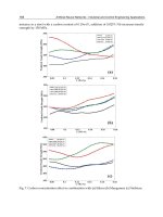
Figure 29.1 Effect of pressure on viscosity of HVI
paraffinic oils
Figure 29.2 Effect of pressure on viscosity of LVI
naphthenic oils