Craniomaxillofacial Reconstructive and Corrective Bone Surgery - part 5 pot
Bạn đang xem bản rút gọn của tài liệu. Xem và tải ngay bản đầy đủ của tài liệu tại đây (5.09 MB, 81 trang )
the ilium in the fascia of the iliac muscle 1 to 3 cm from the
inner cortex of the iliac crest.
Overlying and superior to the iliac crest a skin island can
be harvested. The skin portion is nourished by perforating
vessels from the DCIA and DCIV, which reach the surface
on the medial aspect of the iliac crest at a distance of 1 to 2
cm. The axis of the skin flap lies between the superior infe-
rior iliac spine and tip of the scapula. Dissection starts with
the exposure of the femoral artery, which can be easily pal-
pated caudally to the inguinal ligament. Further dissection in
the proximal direction leads to the DCIA, which leaves on
the lateral aspect of the vessel, now called the external iliac
artery, normally 1 to 3 cm cranially to the inguinal ligament
(Figure 25.15). After that the DCIA and frequently the two
accompanying veins are dissected as a bundle in a craniolat-
eral direction. Dissection comes to a stop at 2 to 3 cm from
the anterior superior iliac spine (Figure 25.16).
To raise an osteomuscular bone flap with a skin island, the
desired skin portion is now dissected free. The incision di-
vides skin and subcutaneous tissues down to the underlying
abdominal fascia. Medially to the anterior superior iliac spine,
the lateral cutaneous femoral nerve should be exposed and
preserved. The external and internal oblique as well as the
transverse abdominal muscles are now incised 3 to 4 cm cra-
nially to the iliac crest (Figure 25.17). The muscle portion of
the flap must remain attached to the fascia and the skin so as
not to harm the blood supply of the skin. The strip of ab-
dominal muscle attached to the medial aspect of the iliac crest
contains the perforating vessels, which are very sensitive and
may be harmed even by shearing the different soft tissue lay-
ers against each other. At 3 to 4 cm superior to the iliac crest,
the transverse abdominal muscle is represented through the
transverse fascia, which is also incised. The abdominal wall
is retracted medially, and the junction between transversal fas-
cia and the fascia of the iliac muscle is identified (Figure
25.18). The vascular pedicle lies in the duplication of the two
fascias and can be palpated at this stage.
The muscles on the lateral aspect of the ilium are then
stripped. The periosteum can either be elevated or left in place
if additional soft tissue coverage of the bone is desired. The
302 M. Ehrenfeld and C. Hagenmaier
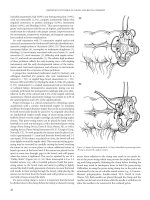
FIGURE 25.16 The vascular pedicle containing the DCIA and in most
cases two accompanying veins is dissected.
F
IGURE 25.18 The fascia of the iliacus muscle together with a 2- to
3-cm strip of muscle must also be included in the flap. The iliacus
muscle can be divided by blunt dissection.
F
IGURE 25.15 The femoral artery and vein are identified. After that
the skin overlying the inguinal ligament is incised and the junction
of the fascias of the abdominal wall and the thigh is exposed. The
inguinal ligament is cut parallel to the axis of the DCIA and DCIV.
F
IGURE 25.17 The edges of the skin island are cut down to the un-
derlying fascia after the vascular pedicle has been isolated. The three
layers of the abdominal muscles are divided leaving a muscle strip 3
cm wide attached to the bone and the overlying skin. The vascular
pedicle lies in the junction of the iliacus and the transversalis fascia.
bone is then osteotomized with an oscillating saw in the de-
sired size and shape (Figure 25.19). The osteotomy site is
sealed with bone wax (Figure 25.20). The iliac bone flap is
completely freed from all surrounding tissues and remains
only connected to the vascular pedicle. If there is any delay
in the craniofacial part of the operation (tumor ablation, prepa-
ration of the recipient site), the flap is deposited in a subcu-
taneous pocket. Shortly before transplantation, the DCIA and
then the DCIV are ligated and transected. The flap may be ir-
rigated with saline solution but is not routinely rinsed with
anticoagulants.
For raising of an osteomuscular iliac bone flap without a
skin or a separate muscle island, the dissection is performed
very similarly to the procedure just described. Because no
skin is taken, the abdominal skin overlying the iliac crest is
incised parallel to the bone. On the medial aspect of the il-
ium, the transverse and oblique abdominal muscles are cut
close to the bone; only a strip of iliac muscle and fascia con-
taining the vascular pedicle is left attached to the medial as-
pect of the ilium.
16,51,52
A special consideration, in obese patients, is that the com-
posite osteomusculocutaneous iliac bone flap provides too
much bulk for intraoral soft tissue reconstruction. As an im-
portant variation, a osteomuscular flap with a large fas-
ciomuscular soft tissue island from the internal oblique mus-
cle can be harvested.
53
Therefore, the fascia of the transverse
abdominal and external oblique muscles is cut close to the il-
iac crest. The internal oblique, underlying the external fascia
and muscle, is now exposed. A nonconstant separate branch
of the DCIA, which leaves the artery on its way between the
internal iliac artery and anterior superior iliac spine, may go
directly to the internal oblique muscle in a mediocranial di-
rection and should be preserved when present. The internal
oblique muscle and its fascia are dissected in the desired
length and remain attached to the medial aspect of the iliac
crest. A strip of iliac muscle containing the vascular pedicle
is also included in the flap. The result is a compound flap of
solid iliac bone with a potentially large soft tissue island of
internal oblique muscle and fascia (Figure 25.21), which can
be used to replace resected intraoral mucosa (Figure 25.22).
Therefore, the intraorally placed muscle and fascia are left to
granulation (Figure 25.23) and subsequent secondary epithe-
lialization from the surrounding mucous membrane. Despite
a certain amount of shrinkage, usually good functional results
can be obtained (Figure 25.24).
Flap Contouring
Especially in chin reconstruction, the only slightly curved il-
iac bone must be bent to adapt it to the shape of a mandible.
For this purpose, the outer cortex (lateral cortex) of the flap’s
bony portion is osteotomized with an oscillating saw (Figure
25.25). The bone cut goes through the outer cortex and the
cancellous portion of the flap. Care must be taken not to pen-
etrate the medial cortex, because in so doing the attached seg-
ment of iliac muscle, the periosteum, and the vascular pedi-
25. Autogenous Bone Grafts in Maxillofacial Reconstruction 303
F
IGURE 25.19 After stripping of muscles and periosteum attached to
the lateral aspect of the iliac crest, the bony portion is cut with an
oscillating saw.
F
IGURE 25.20 The vascular pedicle is ligated and divided after com-
plete isolation of the flap. After sealing the iliac bone with bone wax,
the abdominal wall is closed layer by layer.
F
IGURE 25.21 Osteomuscular bone flap from the hip with attached
internal oblique muscle.
cle may be injured, thus compromising the blood supply. Af-
ter that the bone can be bent in the desired fashion (Figure
25.26).
Scapular Bone and Combined Flaps
The scapula is a triangular-shaped bone with a very thin cen-
ter portion, whereas the borders of the scapula are composed
of more solid bone. The lateral border of the scapula provides
sufficient bone for craniomaxillofacial reconstruction pur-
poses. Pedicled on the circumflex scapular artery and fre-
quently two accompanying veins, bone flaps with a thickness
of approximately 1.5 cm, a height of approximately 3 cm, and
a length of 10 to 14 cm can be harvested. Although the
304 M. Ehrenfeld and C. Hagenmaier
F
IGURE 25.22 The internal oblique muscle can be used to cover de-
fects of the oral mucosa, in this clinical case, of the anterior floor
of the mouth.
FIGURE 25.23 The muscle granulates after transplantation and is sec-
ondarily epithelialized from the surrounding mucosa.
FIGURE 25.24 Clinical situation after the granulation process is fin-
ished.
F
IGURE 25.25 An osteotomy of the former lateral cortex of the hip
now included in osteomuscular iliac bone flap is necessary if the
bone must be bent to adjust it to a special clinical situation.
F
IGURE 25.26 Bone flap after multiple monocortical osteotomies. De-
pending on the desired length of the flap, the bone can either be con-
toured by removing wedges from the lateral aspect of the hip or by
monocortical osteotomies and bending to the medial aspect as shown.
The bone gaps at the osteotomy sites are then filled with cancellous
bone and marrow.
absolute amount of bone depends very much on the indi-
vidual patient’s condition, the lateral border of the scapula
is usually composed of enough bone even for mandible
reconstruction.
The vascular axis containing the circumflex scapular artery
can be elongated in dissecting the subscapular vessels up to
the axilla. Through this technique a long vascular pedicle of
approximately 12 to 14 cm can be created, which has advan-
tages for special indications, among them reconstruction of
the maxilla or mandible in a compromised vessel situation.
On the common subscapular vascular pedicle, the scapular
bone flap can be combined with a scapular or parascapular
fasciocutaneous and a musculocutaneous flap from the latis-
simus dorsi muscle. Various flap combinations are also pos-
sible.
Flap dissection is usually performed with the patient
turned on their side. Important anatomic landmarks are the
scapular spine, the lateral border of the scapula, and the
muscle gap between major and minor teres muscles on one
side and the long triceps head on the other side. This mus-
cle gap lies cranially to the middle portion of the lateral
margin of the scapula. The bone is supplied via vessels run-
ning in a deep plane parallel to the lateral margin of the
bone, whereas two other small terminal branches of the cir-
cumflex scapular artery nourish the scapular and paras-
capular flaps, respectively (Figure 25.27). The scapular flap
is raised over a vascular axis that runs parallel to the scapu-
lar spine approximately in the middle between scapular tip
and scapular spine. The parascapular flap vessel axis also
lies parallel to the lateral margin of the scapula, but in a
subcutaneous plane.
To make microvascular anastomoses easier, it is advisable
to include the subscapular artery and vein in the pedicle and
therefore prepare as much vessel length as possible. The dis-
section of the axillary and subscapular vessels starts with a
skin incision over and parallel to the anterior axillary fold. In
the loose subcutaneous tissues, the junction between axillary
and subscapular vessels is exposed. The circumflex scapular
artery leaves the subscapular artery normally 2 to 4 cm cau-
dally to the axillary vessels. As an important variation, some-
times both arteries leave the axillary artery separately. Two
veins normally run with the circumflex scapular artery; both
should be dissected and preserved. The vascular pedicle is
further dissected medially into the lateral muscular gap. Care-
ful ligation of small vessels to the surrounding muscles is
mandatory. To gain better access, the skin overlying the vas-
cular pedicle can be incised. The muscle gap beside the lat-
eral scapular border is palpated and localized. After retrac-
tion of the latissimus dorsi and teres major muscles, the
vascular pedicle can be seen in the muscle gap. There the sub-
scapular vessels divide into three terminal branches, one to
the bony portion and the remaining two to the scapular and
parascapular skin islands.
If a combination of a bone flap together with a scapular or
a parascapular flap is desired, the size of the soft tissue island
must be defined at that stage of the operation. This is usually
performed with the help of an individual template. Then, an
incision is made through skin and underlying fascia and the
soft tissue flap is raised from the muscle. This is performed
from medially to laterally in the case of the scapular and in
a caudal-cranial direction so far as the parascapular flap is
concerned. Lateral to the bony border, in the region of the
muscle gap, both skin flaps must remain in connection with
the circumflex scapular vessels.
If a osteomuscular bone flap without additional skin flaps
is desired, the skin overlying the scapula is simply incised
parallel to the lateral bone margin from the scapular spine to
the tip. On the lateral aspect of the scapula, the teres minor
muscle inserts cranially and the teres major muscle inserts
caudally. The muscles are cut leaving a muscle strip at least
1 cm wide attached to the bone. The vascular pedicle is thus
protected. Osteotomy of the bone is now performed from pos-
terior with a saw (Figure 25.28). The upper osteotomy line
must remain approximately 2 cm from the glenoid fossa. Now
the one strut, which is still connected to the underlying mus-
cles, is elevated.
The subscapular muscle, which has its origin on the costal
aspect of the scapula, is incised leaving a muscle strip of
approximately 1 cm attached to the bone. The bone or com-
bined bone and soft tissue flap is now completely isolated
on its vascular pedicle, and the latter is ligated in the de-
sired length (Figure 25.29). If the subscapular vessels are
included in the vascular axis, the thoracodorsal artery and
vein must also be ligated. Preserving these vessels allows
various flap combinations potentially including a scapular
bone flap, scapular and parascapular soft tissue flaps, and
25. Autogenous Bone Grafts in Maxillofacial Reconstruction 305
F
IGURE 25.27 Bone grafts from the glenoid fossa to the tip can be
taken from the lateral aspect of the scapula. Pedicled on the cuta-
neous branches of the circumflex scapular artery, a scapular or para-
scapular skin flap (or both) can be harvested in addition. Before dis-
section of the lateral border of the scapula, the crista scapulae and
the muscular gap between teres minor and major muscles and the
long head of the triceps muscle are palpated and marked.
a musculocutaneous latissimus dorsi flap,
19,51,52
(Figure
25.30).
Fibula Bone and Combined Flaps
The fibula is a source for long bone flaps with a compact bone
structure. The flap can be harvested with the patient lying on
the back, side, or abdomen. A two-team approach in max-
illofacial reconstructive surgery can usually only be achieved
with the patient in a supine position. The patient’s leg is flexed
in both hip and knee with the hip joint in inward rotation. In
this position the complete fibula can normally be palpated
through the skin from the fibula head to the lateral malleolus
(Figure 25.31).
The supplying vessel of the fibula bone and combined flap
is the peroneal artery, which rarely is also the dominant vas-
cular supply for the foot. Therefore, before flap harvesting an
angiogram is mandatory. The vascular axis of the bone flap
lies medial to the fibula. The bone itself is nourished mainly
via perforators to the medial periosteum. As a consequence,
stripping of the medial periosteum during dissection or flap
fixation must be avoided. Dissection of the bone flap starts
with the incision of the skin on the lateral aspect of the fibula.
306 M. Ehrenfeld and C. Hagenmaier
FIGURE 25.28 After dissection of the circumflex scapular vessels,
and, if a long vascular pedicle is required the subscapular vessels as
well, the desired fasciocutaneous flap is elevated first. The muscles
attached to the lateral border of the scapula are then divided leav-
ing a strip of muscle approximately 2 cm wide attached to the bone.
The muscles inserting on the posterior aspect of the scapula are also
divided, leaving a thin muscle cuff in place. The bone is cut with a
saw and elevated. After access is given to the costal surface of the
scapula, the subscapular muscle is divided.
FIGURE 25.30 Combination of osteomuscular and fasciocutaneous
scapula and a musculocutaneous latissimus dorsi flap on the com-
mon subscapular vascular pedicle.
F
IGURE 25.29 The osteomuscular and the fasciocutaneous portions
of the combined flap are isolated and pedicled on the common vas-
cular axis represented by the circumflex scapular vessels. The latis-
simus dorsi muscle is elevated. Now the flap can be transposed an-
teriorly into the axilla, and the subscapular vessels can be dissected
to gain a longer vascular pedicle. An additional portion of a latis-
simus dorsi flap pedicled on the thoracodorsal vessels can also be
included in the flap.
FIGURE 25.31 For harvesting of a fibula flap, the patient’s leg is
flexed in both hip and knee with the hip joint in inward rotation. In
this position the complete fibula is palpated through the skin from
the fibula head to the external malleolus and marked. An ovally
shaped skin island can be harvested parallel to the bone axis and
overlying the proximal two-thirds of the bone.
The common popliteal nerve, which runs in a subcutaneous
plane lateral to the fibular head, is exposed and preserved.
The subcutaneous tissues are separated down to the deep mus-
cular fascia. After that, the so-called posterior intermuscular
septum between the anteriorly (long and short peroneal mus-
cles) and posteriorly located muscles (soleus muscle, long and
short flexor hallucis muscles) is dissected (Figure 25.32).
Blunt dissection of the anteriorly and posteriorly located mus-
cles gives good access to the lateral surface of the fibula. The
peroneal muscles are freed from the fibula, whereas the peri-
osteum should remain attached to the bone because stripping
of the lateral periosteum may lead to an elevation of the pe-
riosteum on the medial side, thus separating the vascular pedi-
cle from the bone. Preservation of the periosteum is essential
for the blood supply to the bony portion of the flap.
This first step of the dissection ends when the anterior edge
of the fibula is reached. Adherent to the anterior edge is the
anterior intermuscular septum. It is cut close to the bone, and
then the long and short extensor digitorum muscles are also
separated from the bone again in an epiperiosteal plane. Di-
rectly in front of the fibula, the anterior tibial artery and vein
can be palpated and inspected after the extensor muscles have
been cut. These vessels must be preserved; together with the
extensor muscles they are retracted to the side. The in-
terosseous membrane is exposed over and cut shortly above
the fibula. The vascular axis of the fibula flap containing the
peroneal vessels, lying on the medial aspect close to the bone,
must be handled with great care. Now the fibula is os-
teotomized in the desired length to allow sufficient access to
the soft tissues on the posteromedial side of the bone (Figure
25.33). The bony segment is mobilized laterally and posteri-
orly. Behind the distal osteotomy line the peroneal vessels are
identified and ligated. The vascular pedicle lies posterior to
the interosseous membrane embedded in loose connective tis-
sues. In this stage of the dissection, care must be taken to not
separate the vessels from the periosteum. Finally, the peroneal
vessels are dissected proximally up to the popliteal vessel and
then ligated.
If a fibula flap with a skin paddle is required, the planning
starts with the definition of the desired amount of skin. The
axis of the skin portion overlies the lateral border of the fibu-
lar bone and the posterior intermuscular septum. Blood sup-
ply to the skin is brought by septocutaneous or musculocuta-
neous perforators out of the peroneal vessels, which are
located in the posterior intermuscular septum and sometimes
in the soleus muscle close to the muscle surface. To make
perfusion of the skin island safer, it is recommended that a
strip of soleus muscle adjacent to the intermuscular septum
be included in the flap.
The posterior and anterior edges of the flap are incised and
the skin is elevated on both sides together with the deep fas-
cia. Via the posterior intermuscular septum, the center of the
flap always remains in close contact to the lateral aspect of
the bone. The skin portion is now elevated anteriorly and the
dissection is directed toward the posterior crural septum, un-
til the perforators can be identified in the subcutaneous layer.
The bone is now divided into the desired lengths, after which
further soft tissue dissection is easier. The soleus muscle is
separated from the fibula, leaving a thin strip of muscle (about
1.0 cm) attached to the bone. The flexor hallucis longus mus-
25. Autogenous Bone Grafts in Maxillofacial Reconstruction 307
F
IGURE 25.33 Harvesting of a bone-only flap. After detaching the
muscles on the lateral and anterior surface of the fibula, the bone is
divided and transposed laterally. After that the peroneal vessels are
easily identified. A strip of the posterior tibialis and hallucis longus
muscles together with the periosteum remains attached to the bone.
F
IGURE 25.32 Cross cut through the lower leg. The supplying per-
oneal vessels are lying on the medial aspect of the bone. The skin
island is nourished by perforators from the peroneal vessels, which
come around the posterior surface of the fibula into the posterior in-
termuscular septum. Sometimes they are lying in the soleus muscle
close to the muscle surface. Therefore, some authors recommend in-
cluding a strip of soleus muscle in the flap.
cle is separated, and then the peroneal vessels are ligated and
cut at the distal end of the flap. The final steps of the dissec-
tion are similar to the dissection of a bone-only flap.
51–53
Radial Forearm
Osteomuscular-Fasciocutaneous Flap
The fasciocutaneous distal radial forearm flap today seems to
be one of the most popular flaps for intraoral reconstruction.
54
The thin and pliable flap is pedicled on the radial artery and
the deep venae commitantes. For venous drainage of the soft
tissue flap, subcutaneous veins from the forearm are also suf-
ficient. The radial artery and the accompanying veins lie in a
duplicate of the antebrachial fascia. From there small vessels
ascend to the overlying skin, and other vessels descend to the
brachioradialis muscle. Together with a part of this muscle,
a segment of the radius can be taken, thus turning the fas-
ciocutaneous soft tissue into a fasciocutaneous-osteomuscu-
lar radial forearm flap.
Harvesting of the composite radial forearm flap has quite
a significant donor site morbidity; radius fractures in up to
20% of the cases have been reported. The available bone is
very small in width, height, and length. Therefore, the radial
forearm bone and soft tissue flap is not a flap of first choice
for functional mandible reconstruction.
References
1. Axhausen W. Die Bedeutung der Individual- und Artspezifität
der Gewebe für die freie Knochenüberpflanzung. Hefte Unfall-
heikunde. 1962;72:1.
2. Schweiberer L. Experimentelle Untersuchungen von Knochen-
transplantaten mit unveränderter und denaturierter Knochen-
grundsubstanz. Hefte Unfallheilk 103. Berlin: Springer; 1970.
3. Bardenheuer B. Über Unter- und Oberkieferresektion. Verh
Dtsch Ges Chir. 1892;21:123–130.
4. Sykoff V. Zur Frage der Knochenplastik am Unterkiefer. Zen-
tralbl Chir. 1900;27:81.
5. Krause F. Unterkiefer-Plastik. Zentralbl Chir. 1907;34:1045–
1046.
6. Axhausen G. Histologische Untersuchungen über Knochentrans-
plantationen am Menschen. Dtsch Z Chir. 1908;91:388–428.
7. Lexer E. Die Verwendung der freien Knochenplastik nebst Ver-
suchen über Gelenkversteifung und Gelenktransplantation. Arch
Klin Chir. 1908;86:939.
8. Rydygier LRV. Zum osteoplastischen Ersatz nach Unterkiefer-
resektion. Zentralbl Chir. 1908;35:1321–1322.
9. Lindemann A. Über die Beseitigung der traumatischen Defekte
der Gesichtsknochen. In: Bruhn C, Hrg. Die gegenwärtigen Be-
handlungswege der Kieferschußverletzungen. Hefte IV–VI.
Bergmann Wiesbaden: 1916.
10. Matti H. Über freie Transplantation von Knochenspongiosa.
Langenbecks Arch Clin Chir. 1932;168:236.
11. Converse JM. Early and late treatment of gunshot wounds of
the jaw in French battle casualities in North Africa and Italy.
J Oral Surg. 1945;3:112–137.
12. Conley JJ. Use of composite flaps containing bone for major re-
pairs in the head and neck. Plast Reconstr Surg. 1972;49:522.
13. Boyne P. Methods of osseous reconstruction of the mandible
following surgical resection. J Biomed Mat. 1973;4:195.
14. Taylor GI, Miller G, Ham F. The free vascularized bone graft.
A clinical extension of microvascular techniques. Plast Recon-
str Surg. 1975;55:553–554.
15. O’Brien B McC. Microvascular Reconstructive Surgery. Edin-
burgh: Churchill Livingstone; 1977.
16. Taylor GI, Townsend P, Corlett R. Superiority of the deep cir-
cumflex iliac vessels as the supply for free groin flaps. Plast Re-
constr Surg. 1979;64:745.
17. Quillen CG. Latissimus dorsi myocutaneous flap in head and
neck reconstruction. Plast Reconstr Surg. 1979;63:664.
18. Ariyan S. The viability of rib grafts transplanted with the peri-
ostal blood supply. Plast Reconstr Surg. 1980;65:140–151.
19. Swartz WM, Banis JC, Newton ED, Ramasastry SS, Jones NF,
Acland R. The osteocutaneous scapular flap for mandibular and
maxillary reconstruction. Plast Reconstr Surg. 1986;77:530–
545.
20. Axhausen W. Die Quellen der Knochenneubildung nach freier
Transplantation. Langenbecks Arch Klin Chir. 1951;279:439–
443.
21. Axhausen W. Die Knochenregeneration—ein zweiphasiges
Geschehen. Zentralbl Chir. 1952;77:435–442.
22. Chalmers J. Transplantation immunity in bone homografting.
J Bone Joint Surg. 1959;41B:160–179.
23. Williams RG. Comparison of living autogeneous and homoge-
neous grafts cancellous bone heterotopically placed in rabbits.
Anat Rec. 1962;143:93.
24. Heiple KG, Chase SW, Herndon CH. A comparative study of
the healing process following different types of bone transplan-
tation. J Bone Joint Surg 1963;45A:1593.
25. Ray RD, Sabet TY. Bone grafts: cellular survival versus induc-
tion. J Bone Joint Surg. 1963;45A:337.
26. Burwell RG. Osteogenesis in cancellous bone grafts: considered
in terms of cellular changes, basic mechanisms and the per-
spective of growth control and its possible aberrations. Clin Or-
thop. 1965;40:35–47.
27. Lentrodt J, Höltje WJ. Tierexperimentelle Untersuchungen
zur Revaskularisation autologer Knochentransplantate. In:
Schuchardt K, Scheunemann H, eds. Fortschriffe der Kiefer-und
Gesichts-Chirurgie, Vol. 20. Stuttgart: Thieme; 1976:17–21.
28. Eitel F, Schweiberer K, Saur K, Dambe LT, Klapp F. Theo-
retische Grundlagen der Knochentransplantation: Osteogenese
und Revaskularisation als Leistung des Wirtslagers. In: Hier-
holzer G, Zilch H, eds. Transplantatlager und Implantatlager
bei verschiedenen Operationsverfahren. Berlin: Springer, 1980.
29. Schweiberer L, Brenneisen R, Dambe LT, Eitel F, Zwank L.
Derzeitiger Stand der auto-, hetero- und homoplastischen
Knochentransplantation. In: Cotta H, Martini AK, eds. Implan-
tate und Transplantate in der Plastischen und Weiderherstel-
lungschirurgie. Berlin: Springer; 1981:115–127.
30. Lentrodt J, Fritzemeier CU, Bethmann I. Erfahrungen bei der
osteoplastischen Unterkieferrekonstruktion mit autologen freien
Knochentransplantaten. In: Kastenbauer E, Wilmes E, Mees K,
eds. Das Transplantat in der Plastischen Chirurgie. Rotenburg:
Sasse; 1987:59–61.
31. Steinhäuser EW. Unterkieferrekonstruktion durch intraorale
308 M. Ehrenfeld and C. Hagenmaier
Knochentransplantate—deren Einheilung und Beeinflussung
durch die Funktion—eine tierexperimentelle Studie. Schweiz
Monatsschr Zahnheilk. 1968;78:213.
32. Reuther JF. Druckplattenosteosynthese und freie Knockentrans-
plantation zur Unterkieferrekonstruktion. Berlin: Quintessenz;
1979.
33. Bell WH. Modem Practice in Orthognathic and Reconstructive
Surgery. Philadelphia: WB Saunders; 1992.
34. Sailer HF. Transplantation of Lyophilized Cartilage in Maxillo-
Facial Surgery. Basel: Krager; 1983.
35. Wolford LM. The use of porous block hydroxyapatite. In: Bell
WH, ed. Modern Practice in Orthognathic and Reconstructive
Surgery. Philadelphia: WB Saunders; 1992:854–871.
36. Hoppenreijs TJM, Nijdam ES, Freihofer HPM. The chin as a
donor site in early secondary osteoplasty: a retrospective clini-
cal and radiological evaluation. J Craniomaxillofac Surg.
1992;20:119–124.
37. Sailer HF, Pajarola GF. Plastische Korrekturen an Weichteilen und
Knochen. In: Orale Chirurgie. Stuttgart: Thieme; 1996:308–309.
38. Schliephake H. Entnahmetechniken autologer Knochentrans-
plantate. Implantologie 1994;4:317–327.
39. Tessier P. Autogenous bone grafts from the calvarium for facial
and cranial application. Clin Plast Surg. 1982;9:531–538.
40. Maves MD, Matt BH. Calvarial bone grafting of facial defects.
Otolaryngol Head Neck Surg. 1986;95:464–470.
41. Frodel JL, Marentette LJ, Quatela VC, Weinstein GS. Calvar-
ial bone graft harvest: techniques, considerations, and morbid-
ity. Arch Otolaryngol Head Neck Surg. 1993;119:17–23.
42. Payr E. Über osteoplastischen Ersatz nach Kieferresektion
(Kieferdefekten) durch Rippenstücke mittels gestielter Brust-
wandlappen oder freier Transplantation. Zentralbl Chir.
1908;35:1065–1070.
43. Klapp R. Über chirurgische Behandlung der Kieferschußbrüche.
Z Ärztl Fortbild. 1916;13:225–232.
44. Rehrmann A. Das freie Knochentransplantat zum Unterkiefer-
ersatz unter besonderer Berücksichtigung der Kinnrekonstruk-
tion. In: Schuchardt K, Schilli W, eds. Fortschritte der Kiefer-
und Gesichts Chirurgie, vol. 23. Stuttgart: Thieme; 1978:39.
45. Riediger D, Ehrenfeld M. Der vaskularisierte Knochenspan, ex-
perimentelle Grundlagen und klinische Anwendung. In: Kas-
tenbauer E, Wilmes E, Mees K, eds. Das Transplantat in der
Plastischen Chirurgie. Rotenburg: Sasse; 1987:4–9.
46. Esser E, Mrosk T. Langzeitergebnisse nach Unterkieferrekon-
struktionen mit avaskulärem Spongiosatransfer und Titangitter.
In: Schwenzer N, ed. Fortschritte der Kiefer- und Gesichts
Chirurgie, vol. 39. Stuttgart: Thieme; 1994:90–92.
47. Michel C, Reuther J, Meier J, Eckstein T. Die Differen-
tialindikation mikrochirurgischer und freier autogener Knochen-
transplantate zur Rekonstruktion des Unterkiefers. In: Schwen-
zer N, ed. Fortschritte der Kiefer- und Gesichts Chirurgie, vol.
39. Stuttgart: Thieme; 1994:96–100.
48. Riediger D, Schmelzle R. Modifizierte Anwendung des myoku-
tanen Latissimus dorsi-Lappens zur Defektdeckung im Mund-
KieferGesichtsbereich. Dtsch Z Mund Kiefer Gesichts Chir.
1986;10:364–374.
49. Jack U. Vergleichende Untersuchung zahnärztlicher Implantat-
systeme auf ihre Eignung zur Implantation in Rippentransplan-
tate. Thesis. Germany: University of Tübingen; 1994.
50. Hammer B, Prein J. Differentialindikation mikrochirurgischer
Knochentransplantate für die Rekonstruktion des Unterkiefers.
In: Bootz F, Ehrenfeld M, eds. Aktuelle Ergebnisse des mikro-
vaskulären Gewebetransfers im Kopf-Hals-Bereich. Stuttgart:
Thieme; 1995:149.
51. Strauch B, Yu HL. Atlas of Microvascular Surgery. New York:
Thieme; 1993.
52. Riediger D, Ehrenfeld M. Mikrochirurgie. In: Hausamen JE,
Machtens E, Reuther J, eds. Kirschnersche allgemeine und
spezielle Operationslehre. Mund-, Kiefer- und Gesichtschirurgie.
Heidelberg: Springer; 1995:559–615.
53. Urken ML, Weinberg H, Vickery C, Buchbinder D, Lawson W,
Biller HF. The internal oblique-iliac crest free flap in compos-
ite defects of the oral cavity involving bone, skin, and mucosa.
Laryngoscope. 1991;101:257–270.
54. Soutar DS. The radial forearm flap in intraoral reconstruction.
In: Riediger D, Ehrenfeld M, eds. Microsurgical Tissue Trans-
plantation. Chicago: Quintessence; 1989:31–38.
25. Autogenous Bone Grafts in Maxillofacial Reconstruction 309
26
Current Practice and Future Trends in
Craniomaxillofacial Reconstructive and
Corrective Microvascular Bone Surgery
Hubert Weinberg, Lester Silver, and Jin K. Chun
The introduction of vascularized bone grafting has dramati-
cally improved the potential for reconstruction of complex de-
fects of the mandible, and it has improved the results of sur-
gical restoration of the midface and cranial regions following
tumor ablation or severe trauma. The reconstruction of the
mandible in particular had been fraught with many difficul-
ties, especially by the unfavorable milieu caused by oral con-
tamination. The requirements of the reconstructed mandible
include the maintenance of structural integrity for mastica-
tion, the successful union of adjacent bone segments, and the
continued mobility of the jaw.
1
Reconstruction of the mid-
face and cranium, on the other hand, has different require-
ments for accurate three-dimensional stable bony replace-
ment. The replacement bone in this region must often be thin
and pliable to provide the proper shape and size.
2
The first vascularized bone grafts (VBGs) were described
for lower-extremity reconstruction by Taylor et al.
3
and
Buncke et al.
4
Shortly thereafter, McKee
5
described the mi-
crovascular rib transposition for mandibular reconstruction.
Since then, there have been numerous studies both of the head
and neck and of the extremities, which have examined the rel-
ative merits of vascularized and nonvascularized bone grafts.
While nonvascularized bone heals by resorption and creeping
substitution, vascularized bone maintains live cells that are
capable of regeneration and provides immediate structural
support.
6-8
In addition, vascularized bone has been shown to
continue to survive in a radiated bed with evidence of callus
formation and a fully viable bone marrow with new bone for-
mation in the subperiosteal and endosteal layers.
9
Mandibular Reconstruction
Absolute indications for reconstructing the mandible with
VBGs were given by Chen et al.
10
and include: (1) osteora-
dionecrosis of the mandible or an irradiated tissue bed; (2)
hemimandibular reconstruction with a free and facing glenoid
fossa; (3) long segment mandibular defect, especially across
the symphysis; (4) inadequate skin or mucosal lining; (5) de-
fects demanding sandwich reconstruction; (6) inability to ob-
tain secure immobilization on the reconstructed unit; (7) fail-
ure of reconstruction by other methods; and (8) near-total
mandibular reconstruction. The advantages of VBGs in these
settings have been clearly demonstrated in extensive clinical
studies. The early success rate in these studies has exceeded
90%, further demonstrating the safety and reliability of
mandibular reconstruction with vascularized bone.
11,12
The ideal qualities of the vascularized bone graft for
mandibular reconstruction have been described by Urken.
13
It should be well vascularized; of sufficient length, width, and
height; easily shaped without compromise to its vascularity;
accessible for a simultaneous two-team approach; and have
minimum donor site morbidity. Particularly for the mandible,
the ideal qualities of the composite soft tissue requirements
also need to be considered. The soft tissue component should
be again well vascularized, thin, pliable, abundant, sensate if
possible, and well lubricated. Often it is the soft tissue com-
ponent and not solely the restoration of bony continuity that
will determine the ultimate success of the mandibular recon-
struction. The soft tissue may be needed to restore external
neck or facial skin, and it may be required for mucosal re-
placement of the mandible, tongue, or pharynx. Soft tissue re-
construction should maintain tongue mobility and allow unim-
peded swallowing and articulation.
The choice of donor sites available for mandibular recon-
struction includes the iliac crest, fibula, scapula, metatarsus,
cranium, rib, radius, ulna, and humerus. At present, in the vast
majority of mandibular reconstructions, the iliac crest, fibula,
or scapula is used. The iliac crest has proven to provide the
best bone stock, especially for primary placement of en-
dosseous dental implants (Figure 26.1).
14
A modification of
the iliac crest osteomyocutaneous free flap including the in-
ternal oblique muscle has been described.
15–17
This latter
muscle provides thin, well-vascularized soft tissue that upon
denervation atrophy approximates the appearance of mucosa.
The fibula provides the greatest bone length of all the VBGs
and can be contoured to that of a mandible with numerous
osteotomies (Figure 26.2).
18
The height of the fibula is, how-
ever, somewhat restrictive in its capacity to accept an en-
dosseous implant, although it can be sectioned and double-
310
26. Current Practice and Future Trends in Craniomaxillofacial Reconstructive and Corrective Microvascular Bone Surgery 311
a
c
b
d
FIGURE 26.1 Deep circumflex iliac artery osteocutaneous flap. (a) Flap
design. (b) Harvested flap in situ. (c) Flap inset with rigid fixation.
(d) Postoperative result.
312 H. Weinberg, L. Silver, and J.K. Chun
a
e
c
b
d
FIGURE 26.2 Fibula osteocutaneous flap. (a) Flap design. (b) Har-
vested flap with osteotomized segments and miniplate fixation
in situ. (c) Postoperative posterior-anterior radiograph. (d) Postop-
erative technetium-99 bone scan demonstrating vascular uptake.
(e) Postoperative result.
dle, and also supplies the lateral border of the scapula (Fig-
ure 26.4). An angular artery, a branch of the thoracodorsal
artery, can also be included in the design of the scapular flap
to allow two separate vascularized bone grafts to be harvested
using a single vascular pedicle.
26
The iliac crest and the fibula, while useful under certain
circumstances, rarely are ideal for reconstruction where thin
bone and skin of good quality and color match are essential
for an optimal result. Recently, reconstruction of small, thin
defects of the orbital region has been accomplished with vas-
cularized cortex taken from the medial supracondylar region
of the femur.
28
Current Research
To reduce the very substantial donor site morbidity inherent
in most vascularized bone graft transfers, attention has re-
cently focused on the prefabrication of vascularized bone
flaps. Based on the preliminary studies of Hirase,
29,30
most
of these studies use a principle of staged flap reconstruction.
In the initial phase of this reconstruction vascularized tissue
with a large identifiable pedicle is induced to perfuse the se-
lected bone graft donor site. The bone remains in situ until
sufficient vascularization has occurred from its new pedicle
that a successful transfer can be accomplished. The great ad-
vantage of this technique is that bone can be harvested from
almost any site in exactly the dimensions that are required
without regard to its native blood supply. The disadvantage
is the necessity for two stages and the possibility that despite
staging, the bone donor will still be inadequately vascularized
by its new vascular pedicle.
31
Another intriguing possibility was initially suggested by Net-
telblad et al.
32
and then more recently revised by Mitsumoto
et al.
33
A vascularized bone graft was formed by placing bone
marrow into cylindrical hydroxyapatite chambers to which al-
lograft demineralized bone matrix powder had been added.
Those chambers that were implanted subcutaneously with im-
plantation of a vascular bundle showed accelerated neovas-
cularization and early bone formation. The possibility that
such prefabricated and preshaped vascularized bone grafts
could be used clinically for elective craniofacial reconstruc-
tion is certainly worth contemplating.
Summary
Microvascular surgery has opened numerous possibilities
for single-stage reconstruction of complex deformities of
the craniomaxillofacial region. Newer techniques will un-
doubtedly further advance the reconstructive options of the
surgeon, perhaps simplifying the sometimes difficult pro-
cedures or allowing more refinement in the everlasting pur-
suit of perfect form and function. Surgery and creativity
must continue to form a close alliance to further refine the
layered to increase its height, as in the double-barrel tech-
nique.
19,20
The cutaneous segment of the fibula flap may also
at times prove to be unreliable. The scapula flap has an ex-
cellent soft tissue component that makes it ideal for soft
tissue restoration in the mandibular region.
21
However, the
bone stock available is again fairly limited as is bone length.
Furthermore, because of patient positioning, a two-team ap-
proach is often needed, thereby increasing the difficulty of
this procedure.
Craniofacial Reconstruction
The indications for use of vascularized bone grafts for cra-
niofacial reconstruction are less well defined than in the
mandible.
26
The soft tissue bed in this region is well vascu-
larized, and often autogenous, nonvascularized bone grafts
and alloplastic substitutes do quite well. Furthermore, well-
described pedicled bone flaps based on the temporoparietal
fascia can be rotated into adjacent regions with little difficulty
(Figure 26.3).
22,23
Should the recipient bed, however, be
scarred with poor vascularization and the required bony re-
construction quite large, then certainly VBGs are indicated
and have been used successfully.
24
Vascularized bone grafts
in these circumstances have been noted to maintain contour
and size very well when followed for periods ranging from 3
to 8 years.
25
The choice of bone graft donor sites will depend on care-
ful analysis of the characteristics of the defect and the corre-
sponding characteristics of the flap. An analysis must there-
fore be made of the extent of bone loss, the soft tissue deficit,
whether skin, mucosa, or both, and the nature of the func-
tional derangement. Computer-generated templates have also
been used to accurately predict size, contour, and orientation
of the VBG.
27
The choice of flap in turn must address the
length of the vascular pedicle, the thickness of the soft tissue
component, the mobility of the soft tissue, the dimensions and
configuration of the bone in relation to the defect, and finally
the associated donor site morbidity.
2
Unlike the mandible,
with a number of recipient blood vessels from which to
choose, in the craniofacial region strong consideration must
be given to the selection and location of a recipient pedicle.
The facial artery and vein are often the best suited for vas-
cular anastomoses in reconstruction of the midface, but they
will probably not be of sufficient length for reconstructions
of the nose and orbit. The superficial temporal vessels, while
at times suitable as recipient vessels, will often be of small
caliber and prove to be inadequate for microvascular anasto-
moses. Vein grafts may be required to achieve a sufficiently
long pedicle, but this will certainly add to the time and com-
plexity of the surgical endeavor.
Probably the most versatile VBG for reconstruction of the
craniomaxillofacial region has been the scapula flap.
19
The
circumflex scapular artery, a branch of the subscapular sup-
plies either a horizontal, vertical, or a combination skin pad-
26. Current Practice and Future Trends in Craniomaxillofacial Reconstructive and Corrective Microvascular Bone Surgery 313
314 H. Weinberg, L. Silver, and J.K. Chun
a
c
b
FIGURE 26.3 Temporoparietal osteofascial flap-superficial temporal artery. (a) Preoperative mandibular contour defect. (b) Harvested flap
in situ. (c) Transposition of flap prior to inset and rigid fixation.
26. Current Practice and Future Trends in Craniomaxillofacial Reconstructive and Corrective Microvascular Bone Surgery 315
a c
db
FIGURE 26.4 Scapula osteocutaneous flap-circumflex scapular artery.
(a) Preoperative composite soft tissue and bony defect. (b) Flap de-
sign demonstrating inferior medial deepithelized paddle to be used
for mucosal lining, inferior lateral bone segment, and superior skin
paddle. (c) 3-Dimensional CT imaging computer-generated template
of bony defect. (d) Postoperative result. (Reprinted with permission:
Rose EM, Norris MS, Rosen JM: Application of high-tech three di-
mensional imaging and computer-generated models in complex fa-
cial reconstructions with vascularized bone grafts. Plast Reconstr
Surg. 1993;91:252–264)
316 H. Weinberg, L. Silver, and J.K. Chun
art and science of reconstruction of the craniomaxillofacial
region.
References
1. Finseth F, Kavarana N, Antia N. Complications of free flap
transfers to the mouth region. Plast Reconstr Surg. 1975;56:
652–653.
2. Coleman J. Osseous reconstruction of the midface and orbits.
Clin Plast Surg. 1994;21:113–124.
3. Taylor GI, Miller GD, Ham FJ. The free vascularized bone graft.
A clinical extension of microvascular techniques. Plast Reconstr
Surg. 1975;55:533–544.
4. Buncke HJ, Furnas DW, Gordon L, Achauer BM. Free osteo-
cutaneous flap from a rib to the tibia. Plast Reconstr Surg.
1977;59:799–804.
5. McKee DM. Microvascular bone transplantation. Clin Plast
Surg. 1978;5:283–292.
6. Berggren A, Weiland AJ, Dorfman H. Free vascularized bone
grafts: factors affecting their survival and ability to heal to re-
cipient bone defects. Plast Reconstr Surg. 1982;69:19–29.
7. Berggren A, Weiland AJ, Dorfman H. The effect of prolonged
ischemia time on osteocyte and osteoblast survival in compos-
ite bone grafts revascularized by microvascular anastomoses.
Plast Reconstr Surg. 1982;69:290–298.
8. Moore JB, Mazur JM, Zehr D, Davis PK, Zook EG. A biome-
chanical comparison of vascularized and conventional autoge-
nous bone grafts. Plast Reconstr Surg. 1984;73:382–386.
9. Altobelli DE, Lorente CA, Handren JH, Young J, Donoff RB,
May JW. Free and microvascular bone grafting in the irradiated
dog mandible. J Oral Maxillofac Surg. 1987;45:27–33.
10. Chen YB, Chen HC, Hahn LH. Major mandibular reconstruc-
tion with vascularized bone grafts: indications and selection of
donor tissue. Microsurgery. 1994;15:227–237.
11. Jewer DD, Boyd JB, Manktelow RT, Zuker RM, Rosen IB, Gul-
lane PJ, et al. Orofacial and mandibular reconstruction with the
iliac crest free flap: a review of 60 cases and a new method of
classification. Plast Reconstr Surg. 1989;84:391–403.
12. Urken ML, Weinberg H, Buchbinder D, Moscoso JF, Lawson
W, Catalano PJ, et al. Microvascular free flaps in head and neck
reconstruction. Report of 200 cases and review of complications.
Arch Otol Head Neck Surg. 1994;120:633–640.
13. Urken ML. Composite free flaps in oromandibular reconstruc-
tion. Arch Otol Head Neck Surg. 1991;117:724–732.
14. Moscoso JF, Keller J, Genden E, Weinberg H, Biller HF, Buch-
binder D, et al. Vascularized bone flaps in oromandibular re-
construction: a comparative anatomic study of bone stock from
various donor sites to assess suitability for enosseous dental im-
plants. Arch Otol Head Neck Surg. 1994;120:36–43.
15. Ramasastry SS, Tucker JB, Swartz WM, Hurwitz DJ. The in-
ternal oblique muscle flap: an anatomic and clinical study. Plast
Reconstr Surg. 1984;73:721–733.
16. Ramasastry SS, Granick MS, Futrell JW. Clinical anatomy of the
internal oblique muscle. J Reconstr Microsurg. 1986;2:117–122.
17. Urken ML, Vickery CB, Weinberg H, Buchbinder D, Lawson
W, Biller HF. The internal oblique-iliac crest osseomyocuta-
neous free flap in oromandibular reconstruction. Report of 20
cases. Arch Otol Head Neck Surg. 1989;115:339–349.
18. Hidalgo DA. Fibula free flap: a new method of mandible re-
construction. Plast Reconstr Surg. 1989;84:71–79.
19. Jones NF, Swartz WM, Mears DC, Jupiter JB, Grossman A. The
“double-barrel” free vascularized fibula bone graft. Plast Re-
constr Surg. 1988;81:378–385.
20. Stoll P. Fibula double barrel technique. In: Greenberg AM, Prein
J, eds. Craniomaxillofacial Reconstructive and Corrective Bone
Surgery: Principles of Internal Fixation Using the AO/ASIF Tech-
nique. New York: Springer-Verlag; 2002.
21. Swartz WM, Banis JC, Newton ED, Ramasastry SS, Jones NF,
Acland R. The osteocutaneous scapular flap for mandibular and
maxillary reconstruction. Plast Reconstr Surg. 1986;77:530–545.
22. McCarthy JG, Zide BM. The spectrum of calvarial bone graft-
ing: introduction of the vascularized calvarial bone flap. Plast
Reconstr Surg. 1984;74:10–18.
23. Rose EH, Norris MS. The versatile temporoparietal fascial flap:
adaptability to a variety of composite defects. Plast Reconstr
Surg. 1990;85:224–231.
24. Yaremchuk MJ. Vascularized bone grafts for maxillofacial re-
construction. Clin Plast Surg. 1989;16:29–39.
25. Stal S, Netscher DT, Shenaq S, Spira M. Reconstruction of cal-
varial defects. South Med J. 1992;85:812–819.
26. Rose EH, Norris MS, Rosen JM. Application of high-tech three-
dimensional imaging and computer-generated models in com-
plex facial reconstructions with vascularized bone grafts. Plast
Reconstr Surg. 1993;91:252–264.
27. Coleman JJ, Sultan MR. The bipedicled osteocutaneous scapula
flap: a new subscapular system free flap. Plast Reconstr Surg.
1991;87:682–692.
28. Kobayashi S, Kakibuchi M, Masuda T, Ohmori K. Use of vas-
cularized corticoperiosteal flap from the femur for reconstruc-
tion of the orbit. Ann Plast Surg. 1994;33:351–357.
29. Hirase Y, Valauri FA, Buncke HJ. Neovascularized bone, mus-
cle, and myo-osseous free flaps: an experimental model. J Re-
constr Microsurg. 1988;4:209–215.
30. Hirase Y, Valauri FA, Buncke HJ. Prefabricated sensate myocu-
taneous and osteomyocutaneous free flaps: an experimental model.
Preliminary report. Plast Reconstr Surg. 1988;82:440–446.
31. Khouri RK, Upton J, Shaw WW. Prefabrication of composite
free flaps through staged microvascular transfer: an experimen-
tal and clinical study. Plast Reconstr Surg. 1991;87:108–115.
32. Nettelblad H, Randolph MA, Leif T, Ostrup LT, Weiland AJ.
Molded vascularized osteoneogenesis: a preliminary study in
rabbits. Plast Reconstr Surg. 1985;76:851–856.
33. Mitsumoto S, Inada Y, Weiland AJ. Fabrication of vascularized
bone grafts using ceramic chambers. J Reconstr Microsurg.
1993;9:441–449.
27
Considerations in the Fixation of Bone
Grafts for the Reconstruction of
Mandibular Continuity Defects
Peter Stoll, Joachim Prein, Wolfgang Bähr, and Rüdiger Wächter
Treatment of malignant tumors of the oral cavity frequently
requires resection of bone that is infiltrated by the tumor. Par-
ticularly, if sections of the mandible are resected, this causes
problems as far as form and function are concerned. Serious
and life-threatening sequelae can occur, especially following
resection of the anterior part of the mandible.
1
The goal of
mandibular reconstruction, however, is not only restitution of
continuity and form but the reestablishment of masticatory
function. The repair of soft tissue defects is highly dependent
on the underlying supporting structures.
A decisive step in the improvement of quality of life in pa-
tients suffering from loss or partial loss of the mandible due
to malignant tumors was the development of reconstruction
plates to bridge the bony defects as shown in our patient (Fig-
ure 27.1). They fulfill special biomechanical and anatomic re-
quirements.
2–6
Temporary or permanent reconstruction of the mandible af-
ter continuity resection by using alloplastic materials has to
take the following conditions into consideration:
1. Stability under function
2. Fixation of the remaining bone stumps in the anatomically
correct position
3. Preservation of the possibility of primary or secondary
bone grafting
4. Preservation of the possibility of adjuvant radiotherapy
Recent investigations have confirmed the clinical experience
that despite the use of those metallic “foreign bodies” an adju-
vant, fractionated radiotherapy is feasible (see Chapter 34).
7–11
Bridging osteosynthesis by using reconstruction plates,
however, represents only one step in the patient’s rehabilita-
tion after continuity resection of the mandible. The low peri-
operative morbidity rate is overshadowed by a high long-term
morbidity rate.
11–16
In addition, if no bony reconstruction is
performed the result may be poor, especially so far as func-
tion is concerned.
Pressure of the plate against the bone may interfere with the
blood circulation within the bony cortex and cause de-
mineralization (Figure 27.2). Experimental studies with over-
sized plates used for the fixation of mandibular fractures in
sheep have shown this phenomenon.
17
After injecting ink into
the sheep’s carotid arteries at the time of sacrifice of the ani-
mal, it was clearly visible that the area underneath the plate
was less well supplied (Figures 27.3 and 27.4). This finding
should not be called stress protection.
18,19
The consequences
are loss of contact between plate and bone, eventually leading
to instability of the entire system. When the plate has lost its
contact with the bone surface, it exerts uncontrolled forces upon
the screws during masticatory function. Primarily well-fixed
screws become overloaded, and the result is loosening of the
screws with further bone loss in the screw holes (Figure 27.5).
Plate fractures (Figure 27.6) as well as hardware extrusion
(Figure 27.7) may also occur following bridging osteosyn-
thesis, even if the soft tissue conditions are adequate.
11
Reconstruction of the bony continuity with alloplastic ma-
terial alone can only be a temporary measure for the major-
ity of the cases. Although 70% of our patients aged 60 or
more years do not want further and/or extensive surgery af-
ter bridging osteosynthesis, the surgeon has to insist and do
a bony reconstruction by using free or microanastomosed vas-
cularized bone graft in a second procedure.
Keeping this in mind, one has to consider whether bone
grafting after continuity resection either by using free or mi-
crovascular grafts should be performed primarily to make a
second operation unnecessary.
The choice of the graft depends on these points:
1. The size and location of the bony defect
2. The type and size of the soft tissue defect (“composite
defect”)
3. The question of preoperative or postoperative radiation
therapy, or both
4. The type of tumor and prognosis for the patient
5. The condition of the recipient area
6. The timing of the reconstruction
7. The donor site morbidity
8. The patient’s compliance
20
9. The question of cost-effectiveness
317
318 P. Stoll et al.
a b
FIGURE 27.1 (a,b) A 34-year-old patient 12 days after resection of
the anterior segment of the mandible and immediate alloplastic re-
construction of the chin area using an AO reconstruction plate [three
F
IGURE 27.2 Resorption underneath a conventional AO recon-
struction plate (3-DBRP) due to pressure against the bone surface
(arrow).
F
IGURE 27.3 Sheep mandible, left side. Red area indicates zone of
disturbance of circulation. The reason was pressure caused by an
oversized plate.
dimensionally bendable reconstruction plate (3-DBRP)]. Percuta-
neous radiation therapy has already started.
Full rehabilitation, however, is achieved only after the reestab-
lishment of masticatory function with osseointegrated dental
implants (Figure 27.8) and prosthetic suprastructures. There-
fore, the bone grafts should be suitable for this procedure.
21
In recent years, microvascular reconstruction of the
mandible has reached enormous popularity.
22
Not only the
number but the success rate of those reconstructions has in-
creased dramatically. In this context, however, it has to be
stressed that the free nonvascularized iliac bone graft still has
its importance as a “workhorse” in the majority of the cases.
The most common donor sites for microvascular bone
grafts are iliac crest, scapula, fibula, and radius.
23
We now
use mainly grafts taken from the fibula or the scapula. As far
as the quality of the bone, the amount of soft tissues, and the
length of the vascular pedicle are concerned, each flap has
specific characteristics.
Problems
The pros and cons of different bone grafts and their indica-
tions have been widely discussed (see Chapter 25),
22,24–32
but
little attention has been given to the various fixation tech-
niques available.
32–36
27. Considerations in the Fixation of Bone Grafts for the Reconstruction of Mandibular Continuity Defects 319
FIGURE 27.4 Cut section through a sheep mandible after fracture fix-
ation with an oversized plate. Zone of demineralization on the left
side where the plate was pressed against the cortex.
F
IGURE 27.6 Clinical site of a plate fracture in a case of alloplastic
repair (arrows).
F
IGURE 27.5 Loosening of screws and osteolysis (arrows).
F
IGURE 27.7 Lateral extrusion of a reconstruction plate 12 months
after surgery.
For understanding the possibilities of graft fixation, the
knowledge of their anatomy and pathophysiology is mandatory.
Fresh autogenous avascular grafts contain all the compo-
nents of living tissue. A certain percentage of osteoblasts is
initially nourished by diffusion until vascularization is com-
pleted. In the first days after grafting these osteoblasts pro-
liferate and start building up a woven bone. Primary osteo-
genesis is achieved by the surviving bone cells and not by the
surrounding soft tissue (osteoblast theory). The breakdown of
the graft’s bone matrix by osteoclasts runs parallel to the com-
position of new woven bone. The leftover mucopolysaccha-
rides induce undifferentiated mesenchymal cells of the in-
growing surrounding tissue to become osteoblasts (induction
theory).
Therefore, the basic prerequisites of a secure integration of
a free avascular bone graft are these:
1. Good vascularization of the surrounding soft tissue
2. Mechanical stability for the transplant
3. Close contact between surface of the bone transplant and
the surrounding soft tissue
4
Avascular bone grafts for the replacement of mandibular bony
substance show a high failure rate when they are inserted in
an unstable surrounding environment. Creeping substitution
through neovascularization is not possible if the bone graft is
not adequately stabilized.
It takes 8 to 12 weeks for the bony transformation at the
contact areas to occur. After primary integration of the trans-
plant it is supposed that further remodeling depends on the
functional load. One has to take into account the expected
loss of bone volume of approximately 25% of the original
free graft, for which the surgeon needs to overcompensate.
37
Cancellous bone has a higher osteogenic potency than com-
pact bone, but as a free iliac crest graft it does not withstand
the mechanical stress when bridging mandibular defects.
In contrast to free avascular grafts, there is no progressive
transformation in microanastomosed grafts, and little bone re-
sorption may occur.
24,34
The bone repair at the contact area
between vascularized graft and mandible resembles the well-
known phenomenon of fracture healing, where even primary
bone healing can take place. Under the conditions of adequate
stability, screws for the fixation of metal plates are osseo-
integrated totally and are not likely to come loose due to re-
modeling processes as in avascular grafts.
In this context it has to be stressed that the grafts have to
be inserted atraumatically. Compression osteosynthesis be-
tween graft and bone remnant is not an issue, but adequate
stability has to be achieved to avoid movement between the
microvascular graft and the bone stump.
Vascularized bone grafts (e.g., iliac crest or fibula) do sur-
vive under unstable conditions as long as their vascular pedi-
cle is intact, but malunion, nonunion, or even displacement
of the bone graft can greatly limit a patient’s masticatory re-
habilitation and overall postoperative outcome.
While the use of miniplates or microplates is propagated
to prevent restriction of blood supply of vascularized
grafts,
34,38,39
on the other hand, stable fixation of the grafts
without the possibility of micromovement is empha-
sized.
15,32,33,35,40,41
In our view miniplates or microplates are too weak to sta-
bilize microvascularized bone grafts adequately. Although
their survival is definitely dependent on the vascular supply
and not on the amount of stability as in free grafts, we have
seen dislocations of grafts because of insufficient stabiliza-
tion with miniplates.
42
In general, it can be stated that vital bone grafts transplanted
with microvascular techniques can be fixed with either a re-
construction plate or several universal fracture plates or some-
times with miniplates. In contrast to this, it must be said that
free avascular grafts must always be fixed with load-bearing
reconstruction plates.
This fixation technique is also most successful in mi-
crovascular defect reconstruction.
43
Particularly in cases with
secondary microvascular bone grafting, when a reconstruc-
tion plate is already in place, the plate can be used as a safe
pattern for adaptation of the graft in the desired shape.
Boyd and Mulholland
36
revised different fixation tech-
niques in vascularized bone grafts. They found a 75% failure
rate by using several 4- to 6-hole dynamic compression plates
320 P. Stoll et al.
a
b
FIGURE 27.8 (a,b) Clinical and radiographic situation after insertion
of dental implants (Bonefit
®
, ITI Strauman, Waldenberg, Switzer-
land) in the case of a patient with a squamous cell carcinoma as well
in the original mandibular bone as in the fibula bone graft. The in-
traoral soft tissue defect was covered by a skin paddle.
for fixation of iliac crest grafts, whereas the success rate was
100% when using reconstruction plates for bridging os-
teosynthesis. This is logical because dynamic compression
plates may exert too much compression at the wrong place,
e.g., within the graft.
Methods
In our unit, bony defects up to a length of 6 cm are usually
reconstructed by using corticocancellous grafts taken from the
iliac crest. Cases exhibiting a compromised recipient site due
to previously performed radiation therapy or for whom fur-
ther radiation therapy is planned are excluded from trans-
plantation of avascular grafts, although the bony defect may
be relatively small. Nevertheless, the use of free corticocan-
cellous hip bone is still a valuable help in the majority of mi-
nor defects, as stated before.
28,44
On the other hand, larger
defects, particularly after irradiation, require microvascular
repair.
45
In the case of defects that require only the replacement of
bone without soft tissues, we prefer the fibula
34
as the graft
of choice. Its architecture is, unlike iliac crest or scapula, sim-
ilar to that of the mandible. Defects up to a length of 25 cm
can be repaired. The graft can be easily adjusted to the shape
of the mandible by using the intersection technique. It is as-
sociated with very low postoperative donor site morbidity,
and last but not least, it allows insertion of dental implants
due to its mandibular-like width.
22,46
The main disadvan-
tage—the limited height—can be overcome by using the
“double-barrel” technique.
47
Since the skin paddle of the fibula is relatively thin and
sometimes exhibits a limited reliability,
48
we use the fibula
osteocutaneous flap or the supramalleolar composite graft
49
only in cases with small soft-tissue defects.
In cases with large soft tissue defects, scapula bone and
parascapular flaps are more appropriate. The scapula, how-
ever, seems to be unfavorable as far as length and diameter
are concerned. Frequently, especially in females,
31
secondary
insertion of dental implants is not possible. In addition, time
in surgery is extended because a simultaneous two-team ap-
proach is not possible. On the other hand, like fibula grafts,
scapula grafts present a low postoperative donor site mor-
bidity rate.
50,51
It is important to understand the appropriate possibilities
for the fixation of different grafts. In our experience, adequate
internal fixation by using reconstruction plates combined with
autogenous bone grafts seems to be most satisfactory. Cor-
ticocancellous iliac crest bone as well as microanastomosed
fibula or scapula grafts can easily be adjusted to the given
curvature of the plate.
Bridging osteosynthesis guarantees stability during the
healing phase (Figure 27.9). Generally, nonvascularized cor-
ticocancellous iliac crest grafts should not be fixed with
screws to the plate. During the remodeling phase, the screws
may come loose and act as a foreign body because the bone
is not vital and is subsequently replaced by newly formed wo-
ven and lamellar bone. Infection and loss of bone can occur.
In those cases fixation of the bone grafts to the remnants
is achieved, for example, by using the AO-3-Dimensionally
Bendable Reconstruction Plate system (3-DBRP), which can
provide compression between the graft and the bone stumps
(Figure 27.10).
Since 1984, we have used the AO-Titanium Hollow Screw
Reconstruction Plate system (THORP). With this system one
cannot exert compression, but because its anchoring device
between the screwhead and plate acts as an “internal fixator,”
it is possible to avoid bone resorption underneath the plate
and secondary instability of the entire osteosynthesis.
5,52–55
By using this system, screw fixation of an avascular graft may
be possible since the screwhead does not move inside the
screw hole. Nevertheless, we intend not to interfere with the
bone’s remodeling and prefer adaptation of the graft to the
plate by using resorbable sutures.
Statistical evaluation of our patient sample, however, has
shown that since we have abandoned fixation of avascular
grafts to the plate by using screws, the infection rate could be
dramatically reduced (screw fixation, N ϭ 97 ϭ 32%; with-
out screw fixation, N ϭ 82 ϭ 4%).
Today we generally do not use nonvascularized bone grafts
in an irradiated bed or when postoperative external radiation
27. Considerations in the Fixation of Bone Grafts for the Reconstruction of Mandibular Continuity Defects 321
a
b
FIGURE 27.9 (a,b) Clinical and radiographic situation after immedi-
ate bone repair using a free nonvascularized iliac crest bone graft in
a case of an ameloblastoma.
therapy is planned. This may contribute to the better results.
On the other hand, microanastomosed bone grafts can be
fixed to reconstruction plates with metal screws. It should
be emphasized though that those screws serve only to hold
the graft in position between the rigidly fixed mandibular
segments.
Since microvascular grafts consist of living tissue and be-
have like an edentulous mandible, osseointegration of the
screws can be expected. Compression of the bone grafts be-
tween the bone remnants is not necessary for fixation but can
carefully be exerted. Impairment of the blood supply of the
graft has to be avoided. Gaps between the bone graft and the
remnant, if any, are filled with bone dust and/or bone slices
or cancellous bone from the iliac crest.
In our hands blood supply of microvascular grafts is not
impaired when using functionally stable AO-reconstruction-
plates (3-DBRP or THORP). On the contrary, this procedure
seems to protect the anastomosis and promote uneventful
healing. Loosening of plate and screws, pseudoarthrosis, and
infection, which can occur from using functionally unstable
fixation devices like miniplates, are unusual in our sample.
Sometimes, however, the use of reconstruction plates is not
possible, especially in cases with composite grafts. Here, sev-
eral smaller plates like universal fracture plates may avoid
impairment of the blood supply of the skin paddle.
Conclusion
Various types of bone graft fixation are used in oral and max-
illofacial surgery. It is important to understand that adequate
stability favors the incorporation of the transplant. Generally,
alloplastic restitution of the mandibular continuity is per-
formed by using a reconstruction plate.
This plate preserves the distance between the bone stumps.
Bone grafts can be adjusted and fixed to the plate either pri-
marily or secondarily. The plate acts like a template for the
shaping of the bone graft because it follows the original
mandibular arch.
Two main types of grafts or flaps are available for auto-
genous reconstruction of mandibular defects. In general, ei-
ther an avascular free-bone graft or a bone graft that is re-
anastomosed with microvascular technique and therefore vital
is used.
While free avascular grafts must always be stabilized with
the help of complete bridging osteosynthesis, there may be
322 P. Stoll et al.
FIGURE 27.10 Schematic drawing of the fixation of a free bone graft for the replacement of a defect in the lateral mandible. The inset shows
loose screws (above) at the time of placement of the graft. By tightening of the screws (below) the graft is fixed via compression.
an option for fixation of microvascular grafts by using smaller
plates. Particularly in cases with large soft tissue defects
where the repair has to be performed by using composite
grafts, a reconstruction plate may hinder the vascular supply
of the soft tissue compartment of the graft. In the majority of
the cases, however, the application of a reconstruction plate
is a comfortable measure to insert a bone graft. Nevertheless,
a microvascular graft with several intersections, which are
necessary to achieve a natural curvature, may be further sta-
bilized by using smaller plates, preferably universal fracture
plates (Figures 27.11 and 27.12).
In the case of secondary bone repair, a primarily applied
reconstruction plate preserves the distance between the bone
stumps during the postoperative follow-up period and facili-
tates the placement of a graft.
The AO-THORP system offers a long-term reliable fixa-
tion that will not fail due to micromovement or bone remod-
eling. The locking-screw plate design makes it possible to
achieve a stable reconstruction by using only three or four
screws per bone stump. The new 2.4 mm Unilock recon-
struction plates with special locking screws have been de-
signed to be similar in function to the AO-THORP system to
prevent screw loosening after graft healing has occurred and
may be used for nonvascular and vascularized grafts (see
Chapter 41 for 2.4 Unilock module specifications). These
newer plates are less thick and may be used in situations where
the AO-THORP system and AO3-DBRP are considered for
use, with caution concerning the size of the graft and defect.
Conventional reconstruction plate systems as the AO-3-
DBRP, where the plate is pressed against the bony surface
during tightening of the screws, may become loose with time
due to bone resorption underneath the plate. Therefore, they
are less suitable for long-term alloplastic repair alone. This
kind of reconstruction device is used preferably in combina-
tion with primary bone repair (Figure 27.13). Then, bony resti-
tution takes place before the plate loses its stability. In addi-
tion, a bone graft can be compressed between the stumps and
fixed by using compression.
27. Considerations in the Fixation of Bone Grafts for the Reconstruction of Mandibular Continuity Defects 323
F
IGURE 27.11 Schematic drawing of the reconstruction of the mandibular body, left angle and ramus with a fibula. Fixation was performed
with several universal fracture plates. The bone gaps at the osteotomy site were filled with cancellous bone.
324 P. Stoll et al.
FIGURE 27.12 (a,b) Radiographic situation with an extensive
ameloblastoma within the mandible preoperatively and postopera-
tively after resection and reconstruction of the defect with a mi-
crovascular fibula graft fixed with universal fracture plates as shown
schematically in Figure 27.11.
a
a
b
b
FIGURE 27.13 (a,b) Clinical and radiographic situation of a vascularized fibula bone repair after extensive resection of an osteosarcoma.
Generally it can be said that primary bone repair by using
free or vascularized bone grafts is easier to perform. Secondary
repair after the formation of scars and soft tissue shrinkage has
taken place is more difficult. This is also due to the deficiency
of the soft tissue layer and compromised vascular supply (es-
pecially after radiation), which may limit the desired treatment.
References
1. Stoll P. Lebensqualität nach radikaler Tumorchirurgie im Mund-
Kiefer-Gesichtsbereich. Aktuel Inf Arzt. 1992;6:2–3.
2. Luhr HH. Ein Plattensystem zur Unterkieferrekonstruktion ein-
schliesslich des Gelenkersatzes. Dtsch Zahnärztl Z. 1976;31:
747.
3. Ewers R, Joos U. Temporäre Defektüberbrückung bei Un-
terkieferresektionen mit osteosynthese-methoden. Dtsch Zahn-
ärztl Z. 1977;32:332–333.
4. Spiessl B. Die Unterkieferresektionsplatte der AO. Ihre An-
wendung bei Unterkieferdefekten in der Tumorchirurgie. Un-
fallheilkunde. 1978;81:389–405.
5. Raveh J, Stich H, Schawalder P, Sutter F, Straumann F. Kon-
servative und chirurgische Massnahmen zur Herstellung der
Kiefergelenksfunktion und neue Möglichkeitn und Methoden
zur Defektüberbrückung am Unterkiefer. Schweiz Monatsschr
Zahnheilk. 1980;90:932–948.
6. Schmoker R. Die funktionelle Unterkieferrekonstruktion. Berlin:
Springer; 1986.
7. Stoll P, Wächter R, Hodapp N, Schilli W. Radiation and osteo-
synthesis? Dosimetry on an irradiation phantom. J Cranio-
maxillofac Surg. 1990;18:361–366.
8. Klotch DW, Gump J, Kuhn L. Reconstruction of mandibular de-
fects in irradiated patients. Am J Surg. 1990;160:396.
9. Gullane PJ. Primary mandibular reconstruction analysis of 64
cases and evaluations of interface radiation dosimetry on bridg-
ing plates. Laryngoscope. 1991;101:1–24.
10. Maurer J, Kirschner H, Halling F, Duhmke E. Klinische und
strahlenphysikalische Untersuchungen über den Einfluss von
Unterkieferrekonstruktionsplatten (MRS) auf die Dosisver-
teilung von ultraharten Photonen. Strahlenther Onkol. 1993;
169:279–284.
11. Stoll P, Wächter R. Tumorbestrahlung und Überbückungsosteo-
synthese? Dtsch Z Mund-Kiefer-Gesichtschir. 1993;15:224–229.
12. Komisar A, Warman S, Danziger E. A critical analysis of im-
mediate and delayed mandibular reconstruction using AO plates.
Arch Otolaryngol Head Neck Surg. 1989;115:830–833.
13. Davidson J, Birt BD, Gruss J. AO plate mandibular reconstruc-
tion: a complication critique. J Otolaryngol. 1991;20:104–107.
14. Freitag V, Hell B, Fischer H. Experience with AO reconstruc-
tion plates after partial mandibular resection involving its con-
tinuity. J Craniomaxillofac Surg. 1991;19:191–198.
15. Schusterman MA, Reece GP, Kroll SS, Weldon MA. Use of the
AO plate for immediate mandibular reconstruction in cancer pa-
tients. Plast Reconstr Surg. 1991;88:588.
16. Kim MR, Donoff RB. Critical analysis of mandibular recon-
struction using AO-reconstruction plates. J Oral Maxillofac
Surg. 1992;50:1152–1157.
17. Rahn B, Prein J. Unpublished experiment. AO Research Insti-
tut, Clavadelerstrasse, CH-7270 Davos/Switzerland, 1973.
18. Predieri M, Gautier E, Sutter F, Tepic S, Perren SM. Vermei-
dung der Porose unter Osteosyntheseplatten. Acta Med Austraca.
1990;17:49.
19. Schiller K, Wolf I, Kessler SB. Die Bedeutung der Knochen-
grösse für das Ausmass der plattenbedingten Zirkulationsschä-
den. Acta Med Austrica. 1990;17:444–447.
20. Wächter R, Lauer G, Fabinger A, Stoll P. Zur Compliance von
Tumorpatienten mit dentalen Implantaten. In: Jahrbuch der
Gesellschaft für Orale Implantologie. Berlin: Quintessenz;
1994;299.
21. Wächter R, Stoll P, Bähr W, Lauer G. Osseointegration of ITI-
dental implants (Bonefit) in non-vascularized and vascularized
mandibular bone grafts. Proceedings of the 1st World Congress
of Osseointegration, Venice, Sept. 29–Oct. 2, 1994.
22. Urken ML. Composite free flaps in oromandibular reconstruc-
tion. Review of the literature. Arch Otolaryngol Head Neck
Surg. 1991;117:724–732.
23. Frodel JL, Funk GF, Capper DJ, Fridrich KL, Blumer JR, Haller
JR, et al. Osseointegrated implants: a comparative study of bone
thickness in four vascularized bone flaps. Plast Reconstr Surg.
1993;92:449–455.
24. Riediger D. Restoration of masticatory function by microsurgi-
cally revascularized iliac crest bone grafts using enosseous im-
plants. Plast Reconstr Surg. 1988;81:861–877.
25. Kärcher H, Penkner K. Ergebnisse der freien und gefässgestiel-
ten Knochenrekonstruktion nach Unterkieferkontinuitätsdefek-
ten. Dtsch Z Mund-Kiefer-Geischtschir. 1991;15:285–291.
26. Kuriloff DB, Sullivan MJ. Mandibular reconstruction using vas-
cularized bone grafts. Otolaryngol Clin North Am. 1991;24:
1391–1418.
27. Divaris M, Goudot P, Princ G, Lalo J, Vaillant JM. Recon-
struction mandibulaire par lambeaux libres osseux microanas-
tomoses. Nos indications actuelles. Ann Chir Plast Esthetique.
1992;37:297–308.
28. Lindqvist C. Mandibular reconstruction with free bone grafts.
Curr Opin Dent. 1992;2:25–37, Review.
29. Mayot D, Perrin C, Lindas P, Dron K. Reconstruction de la sym-
physe mandibulaire par transferts osseux vascularises libres il-
iaques et scarpulaire. Ann Otolaryngol Chir Cervico-faciale.
1992;109:123.
30. Ferri J, Piot B, Farah A, Gaillard A, Mercier J. Notre experi-
ence des lambeaux libres vascularises osseux dans le recon-
structions mandibulaires. Le lambeau brachial extreme, le lam-
beau fibulaire, le lambeau parascapulaire. Rev Stomatol Chir
Maxillofac. 1993;94:74.
31. Bekiscz O, Adant J, Denoel C, Lahaye T. Mandibular recon-
struction. An anatomical study of bone thickness in three donor
sites. 12th Congress of the European Association for Cranio-
Maxillofacial Surgery, The Hague, 5–10 September 1994.
32. Komisar A, Shapiro BM, Danziger E, Szporn M, Cobelli N. The
use of osteosynthesis in immediate and delayed mandibular re-
construction. Laryngoscope. 1985;95:1363–1366.
33. Gullane PJ, Holmes H. Mandibular reconstruction. New con-
cepts. Arch Otolaryngol Head Neck Surg. 1986;112:714–719.
34. Hidalgo DA. Titanium miniplate fixation in free-flap-mandible
reconstruction. Ann Plast Surg. 1989;23:498–507.
35. Buchbinder D, Urken ML, Vickery C, Weinberg H, Biller HF.
Bone contouring and fixation in functional, primary microvascu-
lar mandibular reconstruction. Head Neck. 1991;13:191–199.
27. Considerations in the Fixation of Bone Grafts for the Reconstruction of Mandibular Continuity Defects 325
36. Boyd JB, Mulholland RS. Fixation of the vascularized bone graft
in mandibular reconstruction. Plast Reconstr Surg. 1993;91:274.
37. Hausamen JE, Neukam FW. Transplantation von Knochen. Eur
Arch Otorhinolaryngol I Suppl. 1992:163–177.
38. Hidalgo DA. Aesthetic improvements in free-flap-mandible re-
construction. Plast Reconstr Surg. 1991;88:574–585.
39. Barnard NA, Vaughan ED. Osteosynthetic titanium miniplate
fixation of composite radial forearm flaps in mandibular recon-
struction. J Craniomaxillofac Surg. 1991;19:243–248.
40. Wenig BL, Keller AJ. Microvascular free-tissue transfer with rigid
internal fixation for reconstruction of the mandible following tu-
mor resection. Otolaryngol Clin North Am. 1987;20:621–633.
41. Wenig BL, Keller AJ, Shikowitz MJ, Stern JR, Casino AJ, Pol-
lack JM, et al. Anatomic reconstruction and functional rehabil-
itation of oromandibular defects with rigid internal fixation.
Laryngoscope. 1988;98:154–159.
42. Prein J, Ettlin D, Hammer B. Vor- und Nachteile unter-
schiedlicher Fixationstechniken für mikrovaskuläre Transplan-
tate bei der Unterkieferrekonstruktion. IV. International Sym-
posium on Microsurgery in Reconstructive and Plastic Surgery,
Microsurgery ‘95. Jena 1995; Publication 1998.
43. Stoll P, Bähr W, Wächter R. Die Wertigkeit des Fibulatransplan-
tates bei der Rekonstruktion von Unterkieferdefekten. Proceedings
of the IV International Symposium on Microsurgery in Recon-
structive and Plastic Surgery. Jena 1995; Publication 1998.
44. Tidstrom KD, Keller EE. Reconstruction of mandibular discon-
tinuity with autogenous iliac bone graft: report of 34 consecu-
tive patients. J Oral Maxillofac Surg. 1990;48:336–346.
45. Fossion E, Boeckx W, Jacobs D, Ioannides C, Vrielinck L. La
reconstruction microchirurgicale de la mandibule irradiée par le
lambeau circonflexe iliaque profond. Ann Chir Plast Esthetique.
1992;37:246–251.
46. Huryn JM, Zlotolow JM, Piro JD, Lenchewski E. Osseointe-
grated implants in microvascular fibula free flap reconstructed
mandibles. J Prosthet Dent. 1993;70:443–446.
47. Bähr W, Stoll P, Wächter R. “Fibuladoppeltransplantat” als
gefässgestielter Unterkieferersatz. Dtsch Z Mund-Kiefer-
Gesichtschir. 1994;18:219–223.
48. Schusterman MA, Reece GP, Miller MJ, Harris S. The osteo-
cutaneous free fibula flap: is the skin paddle reliable? Plast Re-
constr Surg. 1992;90:787–793.
49. Wolff KD, Stellmach R. The osteoseptocutaneous or purely sep-
tocutaneous peroneal flap with a supramalleolar skin paddle. Int
J Oral Maxillofac Surg. 1995;24:38–43.
50. Sullivan M, Baker S, Crompton R, Smith-Wheelock M. Free
scapular osteocutaneous flap for mandibular reconstruction.
Arch Otolaryngol Head Neck Surg. 1989;115:1334–1340.
51. Thomassin JM, Bardot J, Inedjian JM. Le lambeau osteocutane
scapulaire dans reconstruction mandibulaire. Rev Stomatol Chir
Maxillofac. 1990;91, Suppl. 1:15.
52. Raveh J, Stich H, Sutter F, Greiner R. Use of titanium-coated
hollow screw and reconstruction system in bridging of lower
jaw defects. J Oral Maxillofac Surg. 1984;42:281–294.
53. Sutter F, Raveh J. Titanium-coated hollow screw and recon-
struction plate system for bridging of lower jaw defects: bio-
mechanical aspects. Int J Oral Maxillofac Surg. 1988;17:267–
274.
54. Stoll P, Wächter R, Bähr W. Bridging lower jaw defects with
AO plates: comparison of THORP and 3-DBRP systems.
J Craniomaxillofac Surg. 1992;20:87–90.
55. Wächter R, Stoll P. Komplikationen nach primärer Unterkie-
ferrekonstruktion mit THORP-Platten. In: Ästhetische und plas-
tisch-rekonstruktive Gesichtschirurgie. Neumann H-J, Hrsg.
Reinbek: Einhorn-Presse-Verlag; 1993;259.
326 P. Stoll et al.