Manufacturing Design, Production, Automation, and Integration Part 7 doc
Bạn đang xem bản rút gọn của tài liệu. Xem và tải ngay bản đầy đủ của tài liệu tại đây (621.9 KB, 25 trang )
7
Metal Forming
Metal forming processes transform simple-geometry billets/blanks into
complex-geometry products through the plastic deformation of the metal
in open or closed dies. Due to the high costs of the dies, however, these
processes are primarily reserved for mass production. Metals to be formed
under (normally compressive) stress must be ductile and have low yield
strength. These properties can be favorably induced, when necessary, by
preheating the billets/blanks prior to their placement in the press. Further-
more, one should note that metal forming processes may take one or a few
iterations (i.e., using one or multiple dies) in yielding near net shape desired
geometries with no or little scrap.
Metal forming processes may be classified into two primary categories:
1. Massive forming processes (for bulk deformation), where parts
undergo large plastic deformation.
2. Sheet-metal forming processes, where (thin-walled) sheets of metal
undergo change in overall shape, but not much in their cross
sections.
In this chapter, we will first briefly overview several common metal
forming processes, but present detailed descriptions for only two of
those that are targeted for discrete parts manufacturing (versus con-
tinuous production, such as for tubes and pipes): forging and sheet
metal forming.
Copyright © 2003 by Marcel Dekker, Inc. All Rights Reserved.
7.1 OVERVIEW OF METAL FORMING
7.1.1 Mechanical Behavior of Metals
Deformation of a solid body can be classified as elastic or plastic: when
unloaded, an elastically deformed body always returns to its original shape
regardless of history, rate, time, and path of loading; the plastic deformation
of a body, on the other hand, depends on all these variables and is subjected
to (permanent) loss of original shape when unloaded. Although the theory
of elasticity is well established and yields accurate predictions of strain (due
to mechanical stress), the theory of plasticity normally yields approximate
solutions to plastic deformation problems.
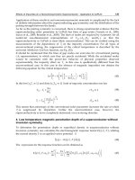
The typical one-dimensional stress–strain curve shown in Fig. 1a for a
tension test would normally be also applicable to the compression of ductile
metals. As a load is applied on a metal part, it elongates in a linear
proportion to the force until the stress level reaches the yield stress value,
Y. At this critical point, when the load is released, the strain level of the part
would be 0.2% or less. At any point before that, the part would completely
recover its original shape. As the load is increased beyond the yield stress
value, the part undergoes plastic deformation in a uniform-elongation phase
until the stress level reaches the ultimate tensile strength value, UTS. At any
point during this phase, if the load is removed, the part would recover the
elastic strain portion of the deformation but permanently maintain the
plastic elongation (or shortening in the case of compression) (Fig. 1b).
FIGURE 1 (a) Stress–strain curve for tension. (b) Loading-unloading cycle for
plastic deformation: F, force; A
o
, cross-sectional area; l
o
, part’s original length; D l,
incremental elongation.
Chapter 7200
Copyright © 2003 by Marcel Dekker, Inc. All Rights Reserved.
Beyond the UTS stress level, the continuing application of load would lead
to nonuniform elongation and eventual fracture of the part. In this context,
ductility is the percentage of plastic deformation that the part undergoes
before fracture.
As mentioned above, in metal forming the preference would be to
process materials whose ductility is high (and that could be made even
higher with increased temperature). Another important factor that we must
take note of in metal forming is the rate of deformation (i.e., the amount of
strain per unit time). It has been accepted that as the rate of deformation is
increased, so would the necessary amount of stress to induce the required
strain rate. As the temperature of the part is increased, however, one can
obtain higher rates of deformation. Thus one can conclude that increasing
temperature raises ductility, lowers yield stress, and thus shortens forming
cycle times.
7.1.2 Common Metal-Forming Processes
Forming processes are broadly classified into massive forming and sheet
metal processes. The former can be further divided into forging, rolling,
extrusion, and drawing, while the latter include proce sses such as
shearing/blanking, bending, and deep drawing. Some of these processes
are briefly discussed below as preamble to a more detailed presentation
of forging and sheet metal forming processes in Secs. 7.2 and 7.3,
respectively. One must note, however, that most parts produced through
metal forming could also be (geometrically) fabricated via casting or
powder processing. It is the manufacturing engineer’s responsibility to
choose the most suitable fabrication method to satisfy the numerous
constraints at hand, such as mechanical properties, dimensional require-
ments, and cost.
Forging
Forging is one of the oldest metal forming processes; it can be traced to
early civilizations of Egypt, Greece, Persia, China, and Rome, when it was
used in the making of weapons, jewellery, and coins. Forging, however,
became a mainstream manufacturing process in the 18th century with the
development of drop-hammer presses. Today, in closed-die forging, a part
can be formed under compressive forces between the two halves of a die,
normally in several steps, or in one step (with or without flash) (Fig. 2). The
thin flash formed during closed-die forging cools quickly and acts as a
barrier to further outward flow of the blank material, thus, forcing it to fill
the cavity of the die.
Metal Forming 201
Copyright © 2003 by Marcel Dekker, Inc. All Rights Reserved.
Rolling
The rolling of metals can be traced to the 16th and 17th centuries in
Europe—rolling of iron bars into sheets. Widespread rolling, however,
was only initiated in the late 1700s and early 1800s for the production of
railway rails. Today, rolling is considered to be mainly a continuous
process targeted for sheet and tube rolling (Figs. 3a, 3b, respectively).
Sheet rolling can be a hot or cold forming process for reducing the
cross-sectional area of a sheet (or slabs and plates with higher thicknesses
than sheets). The workpiece is forced through a pair of rolls repeatedly—
each time reducing the thickness further. A rolling process can be utilized
in shaping the cross section of a workpi ece, such as I-beam s or U-
channels, or reducing the cross-sectional thickness and/or the diameter of
a tube.
FIGURE 2 Closed die forging (a) with flash; (b) without flash.
Chapter 7202
Copyright © 2003 by Marcel Dekker, Inc. All Rights Reserved.
Extrusion
The development and use of continuous extrusion can also be traced to
Europe in the 1800s for the fabrication of pipes. Today, extrusion is utilized
for the fabrication of simple as well complex cross-sectional solid or hollow
products. It is based on forcing a heated billet through a die (Fig. 4). In
direct extrusion, the product is extruded in the direction of the ram move-
ment. In indirect extrusion, also known as backward or reverse extrusion,
the (plastically) deformed product of hollow cross section flows in the
opposite direction to the movement of the ram, (solid cross sections can
also be obtained when utilizing a hollow ram).
Drawing
Drawing reduces the cross-sectional area of a rod, bar, tube, or wire by
pulling the material (in a continuous manner) through a die (Fig. 5), in
FIGURE 3 (a) Sheet rolling; (b) tube rolling.
Metal Forming 203
Copyright © 2003 by Marcel Dekker, Inc. All Rights Reserved.
contrast to the pushing action in extrusion. This process is normally a cold-
working operation and can be carried out with a pair of undriven rolls
instead of a die.
Sheet Metal Forming
Sheet metal forming refers to the forming or cutting/shearing of thin-
walled sh eets into discrete parts, including car body components and
beverage cans. Little or no change in cross-sectional area is expected. In
numerous cases, the amounts of elastic and plastic deformations are
comparable, leaving the engineer to deal with ‘‘springback’’ effects.
Commonly, sheet metal forming is performed on presses through the use
of dies.
FIGURE 4 Extrusion.
Chapter 7204
Copyright © 2003 by Marcel Dekker, Inc. All Rights Reserved.
7.1.3 Materials for Metal Forming
Formability of materials depends on the following factors: process temper-
ature, rate of deformation, stress and strain history, and thermal/physical/
mechanical properties of the material (including composition and micro-
structure). Ductile materials are ideal for forming. Brittle materials must be
powder processed (Chap. 6). A representative list of materials suitable for
metal forming processes is
Forging: Aluminum alloys, copper alloys, carbon and alloy steels,
titanium alloys, tungsten alloys, stainless steel alloys, and nickel
alloys.
FIGURE 5 (a) Die drawing; (b) roll drawing.
Metal Forming 205
Copyright © 2003 by Marcel Dekker, Inc. All Rights Reserved.
Rolling: Aluminum alloys, copper alloys, carbon and alloy steels,
titanium alloys, and nickel alloys.
Extrusion: Aluminum alloys, copper alloys, magnesium alloys, zinc
alloys, lead alloys, titanium alloys, molybdenum alloys, and
tungsten alloys.
Drawing: Alum inum alloys, copper alloys, alloy steels, stainless steels,
cobalt alloys, chromium alloys, and titanium alloys.
Sheet metal forming: Low-carbon steels, aluminum alloys, titanium
alloys, and copper alloys.
7.2 FORGING
Forging is a process in which metal billets are plastically deformed by
compressive forces, normally within closed dies. Today, forging is the most
common metal forming process for the fabrication of discrete solid (versus
thin-walled) parts: connecting rods for the automotive industry, shafts for
aircraft turbines, and gears for a variety of trans portation equipment.
Forged parts, small or large, although formed into net shape geometries,
generally, require additional finishing operations for dimensional as well as
mechanical properties improvements. Forging operations can be performed
either cold or hot. Cold forging at room temperature requires greater
forces than hot forging but yields much better dimensional accuracy and
surface finish.
7.2.1 Forging Techniques
There are a large number of forging techniques, including open-die forging.
Only four of these will be detailed below.
Closed Die Forging
In closed die forging, also known as impression-die forging, the billet
acquires the shape of the cavity formed between the two halves of the die
when closed under pressure (Fig. 2). The process is commonly carried out in
several steps to reduce significantly the amount of force at each formation
step and to minimize the possibility of defects as well as the amount of waste
material (flash). The division of the overall objective into a smaller number
of tasks is part geometry and material dependent. The design of the
intermediate preform dies is a nontrivial task—it will be briefly addressed
in Sec. 7.2.2.
Chapter 7206
Copyright © 2003 by Marcel Dekker, Inc. All Rights Reserved.
The first task in closed die forging is the careful preparation of the
billet/blank: it may be cut from an extruded bar or received directly from
a casting process; subsequently, it is subjected to a preshaping process,
normally through open die forging, when the material is distributed to
different regions of the billet. Fullering distributes material away, while
edging gathers it into an area/region of interest (Fig. 6). An important
preparatory step in the forging process is lubrication through spraying
(1) of the die walls with molybdenum disulfide or other lubricants for
hot processes and (2) of the blank’s surfac e with mineral oils for
cold processes.
Built-in automation is widely utilized in closed die forging for the
transfer of preforms from one cavity into another, commonly within
the same die/press, as well as for the spraying of the die walls with
lubricants. External industrial robotic manipulators have also been used
in the placement of billets/blanks into induction furnaces for their rapid
heating and their subsequent removal and placement into hot forging
presses. Except in cases of flashless forging (Fig. 2b ), these manipu-
lators can also transport the parts into flash trimming and other fini-
shing machines.
Extrusion Forging
Extrusion forging is normally a cold process and can be performed as
forward or backward extrusion. In forward extrusion, a billet placed in a
stationary die is forced forward through a die to form a hollow, thin-walled
object, such as stepped or tapered diameter shafts used in bicycles (Fig. 7a).
FIGURE 6 (a) Fullering; (b) edging.
Metal Forming 207
Copyright © 2003 by Marcel Dekker, Inc. All Rights Reserved.
In backward extrusion, also referred to as impact extrusion, a moving punch
extrudes backward a billet placed in a (closed) cavity, also for the produc-
tion of hollow, thin-walled objects (Fig. 7b).
Orbital Forging
In orbital forging, a metal blank is placed in the lower half of a die and
deformed incrementally by the rotating upper half of the die. Synchronous
to this rotation, the part can be raised upward by a piston that is part of the
lower half of the die (Fig. 8). This process is also referred to as rotary
forging and can be performed as a hot or cold operation. Bearing rings,
bearing end covers, bevel gears, and various other disc-shaped and conical
parts can be rotary forged.
FIGURE 7 (a) Forward extrusion; (b) reverse extrusion forging.
Chapter 7208
Copyright © 2003 by Marcel Dekker, Inc. All Rights Reserved.
Roll Forging
Roll forging forms a metal blank into a desired shape by feeding it through a
pair of rolls with shaped grooves (Fig. 9). The rolls are in operation for only
a portion of their rotational cycle. This hot-forming process is termed
forging although it does not employ a moving hammer/punch. It can be
utilized for the production of long and thin parts, including tapered shafts,
leaf springs, and, occasionally, drill bits (when the blank is also rotated with
respect to the rolls as it advances between them). In a process similar to roll
forging, alloyed steel gears can be manufactured by forming gear teeth on a
hot blank fed between two toothed-die rolls (wheels).
7.2.2 Forgeability and Design for Forging
Forging produces parts of high strength-to-weight ratio, toughness, and
resistance to fatigue failure. Metal flow within a die is affected by the
resistance of the material to flow (i.e., forgeability), the friction and heat
FIGURE 8 Orbital forging.
Metal Forming 209
Copyright © 2003 by Marcel Dekker, Inc. All Rights Reserved.
transfer phenomena at the die/material interface, and the geometry of the
part. Forgeability, in turn, is influenced by the metallurgical characteristics
of the material and the actual process parameters, such as forming temper-
ature and strain rates. Aluminum alloys are the least difficult to forge,
normally at a temperature range of 400 to 550jC. Steels are more difficult to
forge (at 1100 to 1250jC). Tungsten alloys are considered to be the most
difficult materials to forge (at 1200 to 1300jC).
A forging process must ensure adequate flow of the material in the die
cavity, thus preventing the occurrence of external and/or internal defects. As
mentioned above, metal flow is affected by part geometry. Spherical and
block like geometries are the easiest to forge in closed dies. Parts with long,
thin sections or projections are more difficult to forge due to their high
surface-area-to-volume ratios (i.e., increased friction during metal flow and
severe temperature gradients during cooling). Wall thicknesses should be
more than 1 mm for steel and more than 0.1 mm for aluminum. One must
also make allowances for future machining operations and, most impor-
tantly, for material overflow.
As discussed above, complex part geometries require several preform-
ing operations to achieve gradual metal flow. Thus the design of the
intermediate die cavity geometries is one of the most important tasks in
closed die forging. Although often referred to as art, the generation of the
preform cavity geometries (i.e., process planning) would benefit from the use
of computer-aided engineering (CAE) tools (such as finite element model-
ing) for metal flow analysis, as well as from the use of group technology
(GT) tools for accessing past process plans developed for similar part
geometries (Chaps. 3, 5).
One of the objectives of preforming is to minimize the material loss
during forging—the flash. However, it is well established that forging loads
FIGURE 9 Roll forging.
Chapter 7210
Copyright © 2003 by Marcel Dekker, Inc. All Rights Reserved.
increase as flash thickness decreases. Thus, one must optimally design for
suitable flash loss while trying to minimize forging loads.
Other factors that affect closed die forging include
Draft angles:2j to 4j draft angles could facilitate the removal of parts
from die cavities when utilizing mechanical ejectors. These may have
to be increased to 7 to 10j for manual removals.
Corner radii: Sharp corners must be avoided for increased ease of
metal flow.
Parting line: The position of parting lines affects the ease with which
billets can be placed in die cavities and the subsequent removal of
the preforms and finished parts. It also impacts on the grain flow
within the part, and thus on its mechanical properties.
7.2.3 Forging Machines
Presses and hammers are used in the forging of discrete parts. They are
primarily chosen according to the part geometry and material as well as
production rates. Hydraulic mechanical, and screw presses are used for both
hot and cold forging, while hammers are mostly used in hot forging.
Hydraulic Presses
Hydraulic presses can be configured as vertical or horizontal machines and
can operate at rates of up to 1.5 to 2.0 million parts per year. Although they
operate at much lower speeds than do mechanical presses, the ram speed
profile can be programmed to vary during the stroke cycle.
Mechanical Presses
Mechanical presses can also be configured as vertical or horizontal. The
driver system (crank or eccentric) is based on a slider–crank mechanism
(Fig. 10). Since the ram is fitted with substantial guides and since the press is
a constant stroke machine, mechanical presses yield better dimensional
accuracy than do hammers. Knuckle joint (mechanical) presses that can
produce larger loads for short stroke lengths are often used for cold coining
operations. The primary power sources for large mechanical presses are
DC motors.
Screw Presses
Screw presses utilize a friction, gear transmission, electric or hydraulic drive
to accelerate a flywheel–screw subassembly for a vertical stroke (Fig. 10). In
the most common friction drive press, two driving disks (in continuous
Metal Forming 211
Copyright © 2003 by Marcel Dekker, Inc. All Rights Reserved.
motion) are utilized to engage a flywheel through friction (one disk at a
time, for upward and downward motion). The flywheel, in turn, accelerates
the screw attached to it in a downward/upward motion, where maximum
speed is achieved at the end of the stroke.
Hammers
A hammer press is a low-cost forging machine that transfers the potential
energy of an elevated hammer (ram) into kinetic energy that is subsequently
dissipated (mainly) by the plastic deformation of the part. The two most
common configurations are the gravity-drop hammer and the power-drop
hammer (Fig. 11). As the name implies, the former utilizes only gravita-
tional acceleration to build up the forging energy. The latter type supple-
ments this energy through the utilization of a complementary power
source—most commonly hydraulic—for increased vertical acceleration.
The selection of a suitable forging machine for the task at hand is
influenced by several factors: part material and geometry and desired rate of
deformation (i.e., strain rate). Hydraulic presses can achieve a stroke speed
of up to 0.3 m/s and apply a force of typically up to 500 MN in closed die
forging. Mechanical presses can achieve a stroke speed of up to 1.5 m/s and
apply a force of typically up to 100 MN. (A power-drop hammer, in
contrast, can achieve a stroke speed of up to 9 m/s.) Presses are normally
preferred for more ductile materials than those for hammers (e.g., aluminum
versus steel).
FIGURE 10 (a) Mechanical forging press; (b) screw press.
Chapter 7212
Copyright © 2003 by Marcel Dekker, Inc. All Rights Reserved.
7.3 SHEET METAL FORMING
In sheet metal forming, a sheet blank is deformed, normally, into a three-
dimensional object—the deformation usually changes the shape of the part
but not its cross-sectional thickness. Among the numerous sheet metal
forming operations, only a selective few that are most pertinent to discrete
manufacturing will be detailed in this section. They are deep drawing,
blanking/stamping, and bending. Products manufactured through these
processes include desks and cabinets, appliances, car bodies, aircraft fuse-
lages, and a variety of cans.
7.3.1 Sheet Metal Forming Processes
Blanking
The terms blanking and stamping have been used interchangeably to
describe the shearing of planar blanks out of a metal sheet, mostly for their
subsequent forming into three-dimensional objects via other forming oper-
ations. Typically, the sheet metal is secured and a punch/die combination is
utilized to shear a desired cross-sectional geometry. Although the outcome
of shearing is a blank with not-so-smooth edges, if necessary a fine blanking
operation, developed in the 1960s, can be utilized to obtain smooth and
vertical edges, for products that will not be further plastically deformed.
FIGURE 11 Hammers for forging.
Metal Forming 213
Copyright © 2003 by Marcel Dekker, Inc. All Rights Reserved.
As shown in Fig. 12, the blanking force can be reduced if a beveled
punch with an oblique shearing move or other nonflat punches are utilized.
However, if the part is intended to be used with no further forming, the
punch should be either flat or symmetical (with a groove, pointed end, or
hollow face). One must also determine a suitable gap between the punch and
the die (typically 2 to 8% of the sheet’s thickness) for smooth fracture
(shearing). In fine blanking, where the sheet is held in place by a pressure
pad (with V-shaped projections that penetrate the sheet metal for a better
grip), the gap is only about 1%. (Lower clearances are normally reserved for
thin and ductile metals.)
Deep Drawing
Deep drawing is a metal forming process targeted for the production of thin-
walled cup/can shape objects through a combined compression–tension
operation. As shown in Fig. 13, a blank is forced into a die cavity by a
punch and assumes the shape of the punch while being held by the blank
FIGURE 12 Blanking punch die configurations.
Chapter 7214
Copyright © 2003 by Marcel Dekker, Inc. All Rights Reserved.
holder. The process normally maintains the thickness of the sheet metal and
can be used for shallow or deep parts. In an alternative configuration,
reverse drawing, the location of the punch can be reversed, leading to an
upward motion (against gravity).
In certain applications, parts can be deep-drawn in several steps—
redrawing. At each step, the cup becomes longer (deeper) and its diameter is
reduced. However, if the wall thickness needs to be reduced as well, an ironing
operation is implemented. In this process, as the part is redrawn, it is forced
through an ironing ring (like an extra die) placed inside the cavity (Fig. 14).
Ironing is the preferred operation for the fabrication of beverage cans.
In order to achieve production efficiency, it has been proposed that
multiple dies can be vertically aligned in a tandem configuration, thus
allowing greater reductions in wall thicknesses in a single stroke. However,
due to misalignment problems and the necessary long stroke, an alternative
arrangement was developed, a stepped die. In this single-die design, succes-
sive reductions can be achieved within a shorter stroke.
Bending
Bending is one of the simplest, yet widely used, metal forming operations.
Bending of large metal sheet plates into auto body or appliance body parts
FIGURE 13 Deep drawing.
FIGURE 14 Ironing.
Metal Forming 215
Copyright © 2003 by Marcel Dekker, Inc. All Rights Reserved.
are achieved in mass production presses. The operation involves the forcing
of a plate (or parts of it) into simple die cavities (or against a wall) by a
punch. Since elastic and plastic deformations are typically of the same order
of magnitude, the resultant springback effect must be compensated for by
overbending the plate. An alternative to overbending would be to imple-
ment localized plastic deformations for increased resistance to the spring-
back effect.
7.3.2 Formability and Design for Sheet Metal Forming
Although sheet metal forming operations may seem to be simple techniques,
their analysis is complex owing to the possibility of the presence of several
failure mechanisms. Despite the existence of empirically determined ‘‘form-
ability’’ curves for different materials, users are always advised to utilize
CAE tools for stress analysis. Formability has been formally defined as the
ability of the sheet metal to undergo the desired plastic deformation without
failure. In deep drawing, for example, failure or defects can occur owing to
nonuniform thinning of the cup. Tearing can occur at the bottom of the cup
or wrinkling can result at the flange of the cup. The former can be avoided
by allowing strain hardening to occur at preferred rates. Wrinkling, on the
other hand, can be controlled by applying suitable clamping forces.
As implicitly discussed above, the properties of the blank material
influence formability in addition to the process parameters. Alloyed steels,
copper alloys (including bronze), and some aluminum alloys are considered
to have excellent formability characteristics because of their high strain
hardening capabilities. Steels are commonly used in the automotive industry
(body parts, bumpers, shock absorbers, exhaust systems, etc.) and the home
appliance industry, copper alloys are used for a variety of small finished
parts (ballpoint pen cartridges, zip fasteners, screws, etc.) and aluminum
alloys are used in the automotive industry, the aircraft industry, and even in
the shipbuilding industry. Some titanium alloys have also been sheet formed
into parts for the aircraft and aerospace industries.
Layout Planning in Blanking
Optimal positioning of blanks on a strip or a plate can significantly reduce
scrap and therefore result in cost savings (minimizing material to be
recycled) (Fig. 15). The ultimate solution would naturally be having zero
scrap (Fig. 16). One could also have different shapes mixed on a single strip,
for better utilization. Overall, the problem is a classical mathematical
optimization problem, where the variables are the position and orientation
of the blanks on the strip, and the objective function to be minimized is the
surface area of the leftover scrap. (An additional variable set could include
Chapter 7216
Copyright © 2003 by Marcel Dekker, Inc. All Rights Reserved.
the outer dimensions of the strip or the plate—for example, if a single row of
circular blanks yields 40% waste, by increasing the number of rows to 6 and
packing the circles, we could reduce the waste percentage to 25%.)
7.3.3 Dies and Presses for Sheet Metal Forming
As with forging, sheet metal forming may require several steps to obtain the
exact shape of the product: the dies must be designed accordingly, and
presses should be selected for optimal production. Also, as with forging,
manufacturers may decide to combine several preforming cavities (or
operations) into a single die (or a single forming station).
Large sheet metal parts (as those found in the automotive industry) are
almost always manufactured using single-cavity dies installed in large presses
and transferred (sequentially) from one station to another using conveyors or
large robotic manipulators. For smaller parts, several single dies can be
mounted on a common base plate at one press station, where parts are moved
from one die to another (within the same station) automatically.
FIGURE 16 No-scrap production.
FIGURE 15 Optimal part configuration on a strip.
Metal Forming 217
Copyright © 2003 by Marcel Dekker, Inc. All Rights Reserved.
In stamping, ‘‘progressive’’ dies can be used to blank a part in several
stages—i.e., each punch performs one of the many blanking operations
needed on one part. The strip on which the part is mounted (or is part of)
progresses forward after every blanking operation and finally removed
(sheared off) from the strip after the last blanking operation.
Today, manufacturers can decide on choosing dedicated presses for
their specific product at hand or choose universal presses that can do both
stamping and forming (for small-size parts). As described in Sec. 7.2.3, these
presses can be either mechanically or hydraulically driven. However, in the
mass production of large parts, an engineer must also carefully design a
transportation system for the movement of semifinished (preformed) parts
from one station to another. These transportation systems can be of the
continuous-line type or targeted for the transfer of small batches. In either
case, robotic manipulators with magnetic grippers are very widely utilized
throughout the sheet metal forming industry for the loading/unloading/
transfer of parts. These manipulators could be of the stand-alone type or
built in into the press (the dedicated type) and can handle parts weighing
above 50 kg each.
As will be discussed below, in addition to the selection of the most
suitable dies, presses, and transport devices, manufacturers must also pay
special attention to die changing systems. A quick die exchange technique
can significantly increase production efficiency.
7.4 QUICK DIE EXCHANGE
Tactical flexibility in manufa cturing requires companies to respond to
market demand fluctuations in a timely and profitable manner. A key
requirement is to have operational flexibility on the factory floor, whereby
production models and batch sizes of parts can be varied without disrup-
tions. Group technology was discussed in Chap. 3 as a potential facilitator
for the production of families of (similar) parts within (physical or virtual)
workcells. Productivity gains can be achieved in such environments by
having common setup tools and procedures, so that setup transformation
from one part model to another does not require an excessive amount
of time.
In this section, we will briefly review the topic of quick die ex-
change, which is at the heart of productivity improvement through the
elimination of waste (i.e., activities that do not add value to the product).
In this context, the single-minute exchange of dies (SMED) philosophy
proposed by S. Shingo stands out as an excellent starting point. Shingo’s
SMED approach is a vital part of a comprehensive manufacturing
Chapter 7218
Copyright © 2003 by Marcel Dekker, Inc. All Rights Reserved.
strategy that he has advocated since the early 1950s: stockless production,
the minimization of in-process inventories. SMED is a companion to just-
in-time (JIT) manufacturing and defect-free production tactics in this
quest. Many hundreds of applications of the SMED philosophy around
the world have reduced setup times from several hours to a few minutes,
especially in environments of metal forming, metal casting, and plastics
molding.
The above-mentioned time savings, via rapid die exchanges, yield
increased machine utilization in mixed production environments. This
objective is achieved by distinguishing between on-line (internal) and off-
line (external) setup activities and increasing efforts to reduce the former
activities and thus minimizing the time the machine has to be down. Shingo
reports that typically in a setup process on-line activities take up to 70% of
the overall die exchange time. Two thirds of this time, in turn, is spent on
final adjustments and trial runs. Shingo proposes a two-step approach to
waste reduction:
1. Identification and separation of current on-line and off-line
setup activities, whereby subsequently maximizing the latter by
converting as many of the (current) on-line setup tasks as
possible into off-line ones,
2. Reduction of time spent on all on-line and off-line setup activities,
with the greater emphasis being on the on-line tasks
Effective a priori preparation of setup tools and their efficient trans-
portation can significantly reduce time spent on on-line activities. For
example, mechanization of die mounting through moving bolsters, roller
conveyors, revolving die holders, or even through the employment of air
cushions will save setup time. Additional operations that were previously
carried out on-line, but now are classified as off-line, can also be efficiently
carried out to minimize overall setup time. A typical example would be
standardization of the functional elements of different dies—modification
of die geometry for clamping height standardization, use of centering jigs,
and so on.
Reduction of time spent on on-line set-up activities constitutes
the primary objective of any productivity improvement attempt. No long
list of generic guidelines for this objective exists, so tool and die designers
must evaluate every application individually for savings through inge-
nuity and innovation. Shingo does highlight, however, three generic
(common) guidelines:
The use of clamping techniques that miminize the time spent on
securing the die in the press should be a priority. Examples include
Metal Forming 219
Copyright © 2003 by Marcel Dekker, Inc. All Rights Reserved.
FIGURE 17 One-turn clamping.
Copyright © 2003 by Marcel Dekker, Inc. All Rights Reserved.
one-turn attachments (where several points of connection are
achieved with the turn of one mechanism) (Fig. 17), cam and
clamps, spring-loaded pins, etc.
The elimination of as many adjustments as possible through the use of
guiding pins, locators, height gages, or even electronic indicators/
sensors.
The concurrent (versus sequential) implementation of several on-line
tasks. Safety issues should be a paramount concern, however, when
utilizing multiple operators.
As a complementary point to the above discussion, the reader must
be aware that the frequency of exchanging dies is a direct function of total
(on- and off-line) time spent of the setup. Although a die can be removed
from a press and replaced by a different one within minutes, this naturally
does not imply that it can be remounted after a short while. Off-line die
preparation dictates the length of that time. Thus manufacturing engineers
must not neglect the issue of minimizing off-line setup times, even when
they have reduced the on-line activities to several minutes and maximized
machine up-time.
REVIEW QUESTIONS
1. Is metal forming an elastic or a plastic deformation process? Explain.
2. What is material ductility and how does it affect metal forming?
3. Which typical fabrication processes are utilized in the preparation of
billets/blanks for forging?
4. Why is it preferable to have forging carried out in multiple steps?
5. Describe forward and backward extrusion forging, respectively.
6. Why are long and thin part sections difficult to forge?
7. Discuss the flash formation process in forging and define its
advantages/disadvantages.
8. Discuss the selection of a suitable forging machine.
9. Describe the fine blanking process.
10. Describe the redrawing and ironing processes as well as the deep
drawing process that uses multiple dies in tandem or a stepped
die.
11. What is the springback effect in meta l bending?
12. Discuss the optimal posit ioning of blanks on a strip for blanking
operations.
13. What are progressive dies in forging as well as in blanking?
14. Discuss the topic quick die exchange. Differentiate between on-line
(internal) and off-line (external) setup activities.
Metal Forming 221
Copyright © 2003 by Marcel Dekker, Inc. All Rights Reserved.
DISCUSSION QUESTIONS
1. Forging is normally a multistep process: the final shape of the part is
achieved via multiple forming operations in a single die with multiple
cavities using one forging machine. The parts in progress are moved
forward from one cavity to the next after every cycle of the forging.
Discuss methods/technologies that allow users optimally to (process)
plan the manufacturing process. That is, minimize cost (or time) of
manufacturing, subject to achieving the desired geometric and
mechanical properties of the part. Similarly, discuss the load-balancing
issue for multi-cavity (progressive) forging dies: that is, optimal
balancing of the force and energy requirements for the plastic
deformation processes in all the cavities, using computer-aided
engineering analysis tools, so that the forging press is better configured.
2. Single-minute exchange of dies (SMED) is a manufacturing strategy
developed for allowing the mixed production (e.g., multimodel cars)
within the same facility in small batches. The primary objective has
always been to minimize the time spent on setting up a process while
the machine is idle. This objective has been achieved (1) by converting
as many on-line operations as possible to off-line ones (i.e., those that
can be carried out while the machine is working on a different batch),
and (2) by minimizing the time spent on on-line setup operations.
Discuss the effectiveness of using SMED or equivalent strategies in the
mass manufacturing of multimodel products, the mass manufacturing
of customized products, and the manufacturing of small batches or
one-of-a-kind products.
3. During the 20th century, there have been statements and graphical
illustrations implying that product variety and batch size remain in
conflict in the context of profitable manufacturing. Discuss recent
counterarguments that advocate profitable manufacturing of a high
variety of products in a mass production environment. Furthermore,
elaborate on an effective facility layout that can be used in such
environments: job-shop, versus cellular, versus flow-line, versus a
totally new approach.
4. Analysis of a production process via computer-aided modeling and
simulation can lead to an optimal process plan with significant
savings in production time and cost. Discuss the issue of time and
resources spent on obtaining an optimal plan and the actual
(absolute) savings obtained due to this optimization. For example,
spending several hours in planning to reduce production time from 2
minutes to 1 minute. Present your analysis as a comparison of one-
of-a-kind production versus mass production.
Chapter 7222
Copyright © 2003 by Marcel Dekker, Inc. All Rights Reserved.
BIBLIOGRAPHY
Altan, Taylan, Oh, Soo-Ik, Gegel, Harold L. (1983). Metal Forming: Fundamentals
and Applications. Metals Park, OH: American Society for Metals.
Avitzur, Betzalel (1983). Handbook of Metal-Forming Processes. New York: John
Wiley.
Blazynski, T. Z. (1989). Plasticity and Modern Metal-Forming Technology. London:
Elsevier Applied Science.
Carle, D., Blount, G. (1999). The suitability of aluminum as an alternative material
for car bodies. J. of Materials and Design 20:267–272.
Doyle, Lawrence E., et al (1985). Manufacturing Processes and Materials for Engi-
neers. Englewood Cliffs, NJ: Prentice-Hall.
Groover, Mikell P. (1996). Fundamentals of Modern Manufacturing: Materials, Pro-
cesses, and Systems. Upper Saddle River, NJ: Prentice Hall.
Hayashi, H., Nakagawa, T. (Nov. 1994). Recent trends in sheet metals and their
formability in manufacturing automotive panels. J. of Materials Processing Tech-
nology 46(3–4):455–487.
Hosford, William F., Caddell, Robert M. (1993). Metal Forming: Mechanics and
Metallurgy. Englewood Cliffs, NJ: Prentice Hall.
D. Beadle, John (ed.). (1971). Metal Forming. Basingstoke, UK: Macmillan.
Kalpakjian, Serope, Schmid, Steven R. (2000). Manufacturing Engineering and Tech-
nology. Upper Saddle River, NJ: Prentice Hall.
Kobayashi, Shiro, Oh, Soo-Ik, Altan, Taylan (1989). Metal Forming and the Finite-
Element Method. New York: Oxford University Press.
Marciniak, Z., Duncan, J. L. (1992). The Mechanics of Sheet Metal Forming. Lon-
don: E. Arnold.
Pearce, Roger (1991). Sheet Metal Forming. New York: Hilger.
SAE (2000). Sheet Metal Forming: Sing Tang 65th Anniversary Volume. Warrendale,
PA: Society of Automotive Engineers.
Schey, John A. (1987). Introduction to Manufacturing Processes.NewYork:
McGraw-Hill.
Schuler, GmbH. (1998). Metal Forming Handbook. Berlin: Springer-Verlag.
Talbert, Samuel H., Avitzur, Betzalel (1996). Elementary Mechanics of Plastic Flow
in Metal Forming. New York: John Wiley.
Wagener, H. W. (Dec. 1997). New developments in sheet metal forming: sheet ma-
terials, tools and machinery. J. of Materials Processing Technology 72(3):342–357.
Wagoner, R. H., Chenot, Jean-Loup (1997). Fundamentals of Metal Forming. New
York: John Wiley.
Metal Forming 223
Copyright © 2003 by Marcel Dekker, Inc. All Rights Reserved.