Manufacturing Design, Production, Automation, and Integration Part 11 pptx
Bạn đang xem bản rút gọn của tài liệu. Xem và tải ngay bản đầy đủ của tài liệu tại đây (585.33 KB, 21 trang )
11
Workholding—Fixtures and Jigs
Workholding in manufacturing is the immobilization of a part (workpiece)
for the purpose of allowing a fabrication or an assembly process to be carried
out on it. The term fixturing is also commonly used to describe workholding.
Design of workholding devices normally falls within the domain of expertise
of tool designers, who decide what fabrication or assembly tools to use as
well as what fixtures or jigs to employ. The overall objective is to increase
productivity through increased rates of manufacturing: utilize tools with
appropriate lengths of life and fixtures/jigs with optimum accuracies.
A jig is a workholding device, primarily used in hole fabrication, for
locating and holding a workpiece and guiding the production tool (e.g., a
bushing for guiding a drill bit and thus preventing slippage and vibrations
during the engagement of the tool with the workpiece). A fixture, on the
other hand, is a workholding device used in machining and assembly for
securely locating and holding the workpiece without providing a built-in
guidance to the manufacturing tool. Both types of devices, jigs and fixtures,
must provide maximum accuracy (including measures to prevent incorrect
workholding) and be designed for ease of mounting and clamping of the
workpiece by humans or robots.
Design of a workholding device requires a careful examination of
the workpiece (geometry, material, mechanical properties, and tolerances),
the fabrication processes (tool paths, machining/assembly forces, and
Copyright © 2003 by Marcel Dekker, Inc. All Rights Reserved.
environment, e.g., coolant liquids), and the specific machines to be utilized.
An additional issue to be considered is the target setup cost that can be
afforded. Owing to their complexity and high accuracy, workholding devices
can be very expensive. Normally, these one-of-a-kind devices are expected to
be used for a large number of workpieces in mass production, in order to
minimize their per part cost. In case of small-batch or one-of-a-kind product
manufacturing, modular fixtures that can be reconfigured according to the
part geometry at hand should be utilized.
Although modular fixtures have been in existence since the 1940s,
their primary users until the early 1980s were the machine-tool manufac-
turers, who fabricated small-batch or one-of-a-kind lathes, milling ma-
chines, and so on. With the widespread utilization of flexible manufacturing
strategies in the past two decades, such reconfigurable devices have become
very attractive in group-technology-based workcells for the fabrication of a
family of similar parts. In parallel to industrial advancements on the design
of modular fixtures, numerous academic research centers have also devel-
oped (1) reconfigurable and programmable (‘‘flexible’’) fixtures for use in
automated environments, and (2) computer-aided design tools for the
efficient design of fixtures (one-of-a-kind or modular) in concurrent engi-
neering environments.
In this chapter, following the description of general workholding
principles and basic design guidelines for jigs and fixtures, we will review
the use of such devices in manufacturing, in the form of dedicated or modu-
lar configurations. We will also present a brief discussion on the computer-
aided design aspects of fixture/jig development.
11.1 PRINCIPLES OF WORKHOLDING
The design of a workholding device is governed by the geometry of the
workpiece and the dynamics of the manufacturing process in which it is
expected to participate. The fixture/jig must be able to hold the workpiece in
place (i.e., preventing motion and deflections) while it is subjected to
external forces. These forces are most prominent in metal cutting operations
and might cause the workpiece to break away from the workholding device
or to fracture if it were not supported suitably. Thus locating and clamping
will be discussed below in greater detail.
11.1.1 Locating
A solid body has six degrees of freedom (dof) of mobility in uncon-
strained three-dimensional space: three degrees of translational movement
freedom (D
x
,D
y
,D
z
) and three of rotational movement freedom (R
x
,R
y
,R
z
)
Chapter 11364
Copyright © 2003 by Marcel Dekker, Inc. All Rights Reserved.
(Fig. 1). The objective of a workholding device is to eliminate all mobility and
simultaneously provide adequate support to the workpiece to counteract
external forces.
Three-dimensional mobility can be prevented by utilizing six points of
constraint, by the 3-2-1 rule (Fig. 1b): three points (1, 2, and 3) provide a
planar constraint, eliminating two rotational (R
x
and R
y
) and one transla-
tional (-D
z
) dof, two additional (orthogonal) points (4 and 5) eliminate one
more rotational (R
z
) and one more translational (-D
x
) dof and, finally, a
sixth point (6) totally constrains the workpiece by eliminating the last
translational dof (-D
y
). Naturally, as seen from Fig. 1b, this immobility
can be achieved only if the workpiece is pushed against these support points
and held in place by a clamping device.
For the best possible accuracy, locators should contact the workpiece
on its most accurate surfaces (versus unmachined, rough surfaces). Although
point contact would yield best positioning accuracy, most locators have
planar contact surfaces, in order to minimize damage to the workpiece due to
potentially high-pressure contact points. Redundancy in locating should be
avoided, unless necessary for safety reasons or to prevent deflections.
Distribution and configuration of the locators is an engineering analysis
issue: mechanical stress analysis should be carried out for the optimal
placement of locators (Sec. 11.4).
Locators are manufactured separately from the main body of the
workholding device (e.g., a mounting plate) using tool-quality-hardness steel
for minimum wear. They are normally fabricated to exact specifications as
fixed dimension components or as adjustable height locators. Some exem-
plary locators are shown in Fig. 2.
Locators may be placed on the periphery of the object or underneath it
and, occasionally, fitted into existing holes on the workpiece. One must note
that, for example in machining, locators should not be mounted directly on
FIGURE 1 (a) Mobility of a solid body; (b) the 3-2-1 principle.
Workholding—Fixtures and Jigs 365
Copyright © 2003 by Marcel Dekker, Inc. All Rights Reserved.
the machine tool’s table but on the workholding device’s body, which is
subsequently secured onto the machine tool’s table.
11.1.2 Clamping
The role of a clamping device is to apply sufficient force on a workpiece to
maintain its absolute immobility during the manufacturing process. Clamp-
ing forces should be sufficiently high not to allow any loosening due to
potential vibrations and be directed toward support points (in the most solid
sections of the workpiece) to prevent distortion or damage. Forces generated
during manufacturing, however, should be counteracted by the fixed parts of
the workholding device (locators and the base plate) and not by the clamps.
FIGURE 2 Fixed and adjustable locators.
Chapter 11366
Copyright © 2003 by Marcel Dekker, Inc. All Rights Reserved.
As with locators, clamps must allow for rapid loading/unloading of
the fixture/jig and normally be located in the periphery for minimum
interference with the manufacturing operations. The five basic classes of
clamping are briefly described below (Fig. 3):
Strap clamps: The basic configuration comprises a bar, a heel pin, and
a lever or a threaded rod. These clamps are the simplest to use and
are found in most workholding devices.
Screw clamps: The moment developed by a screw is utilized to hold the
workpiece in place. Although simple to use, these clamps are slower
to operate than others.
Cam clamps: Cam-shaped levers are utilized in fast-operating clamping
for direct or indirect application of pressure on the workpiece. Cam-
action clamps would be susceptible to vibrations during the
manufacturing operation.
Toggle clamps: Toggle-action clamps have the ability quickly and
completely to move away from the workpiece once unlocked. The
FIGURE 3 Clamps.
Workholding—Fixtures and Jigs 367
Copyright © 2003 by Marcel Dekker, Inc. All Rights Reserved.
two common configurations used in manufacturing applications are
the ones with the hold-down and straight-line-push actions.
Almost all clamping devices can be power activated using a hydraulic
or electrical power source and occasionally a pneumatic power source. The
obvious advantage of power activation is usefulness for automation.
Commercially available chucks (for lathes) and vises (for milling
machines) are also considered as general-purpose clamping devices. Both
devices can be configured for manual operation or automatic clamping.
There also exist magnetic and vacuum chucks and vises for nonmechani-
cal clamping of workpieces that would not be subjected to large forces
during manufacturing.
11.1.3 Workholding Device Design
The mechanical design of a fixture/jig is a complex engineering task that
includes all the typical steps of a traditional design process: synthesis,
analysis, and prototyping. A tool designer can utilize the techniques
addressed in Chap. 3 for effective fixture/jig design (e.g., axiomatic design
theory, group technology, etc.). The outcome of this process is a specific
fixture/jig configuration (layout), individual component designs, and a
corresponding workpiece loading/unloading procedure.
Prior to the configuration of a suitable workholding device, however,
the following issues must be addressed: the necessity of multiple fixtures/jigs
owing to workpiece geometry complexity, the number of workpieces per
fixture/jig, the determination of suitable surfaces on the workpiece for
locating and clamping, and the sequence of workholding steps. The fix-
ture/jig configuration process would yield the following information:
Types of locators and clamps
Positions of locators and clamps
Clamping sequence and magnitudes of clamping forces
The detailed designs (geometry, dimensions, and tolerances) of indi-
vidual workholding elements are determined by workpiece geometry,
contact information (point, line, or plane contact between the locators
and workpiece surfaces), expected frequency of utilization (e.g., batch
production versus mass manufacturing), availibility of off-the-shelf stand-
ard device geometries, mode of operation (manual versus automatic), and
finally conditions of manufacturing (clean-room versus machining with
coolants). Some jig and fixture design examples will be presented in the
following sections.
Chapter 11368
Copyright © 2003 by Marcel Dekker, Inc. All Rights Reserved.
11.2 JIGS
Jigs are workholding devices used for guiding hole-making tools into
accurately located workpieces. Although used for a variety of hole-making
processes, such as boring, reaming, tapping, etc., the majority of jigs are
utilized for drilling. A typical jig used in drilling would include a baseplate,
or a box, with a number of locators and clamps for holding the workpiece
and (hardened-steel) bushings corresponding to the number of holes to
be drilled.
11.2.1 Jig Configurations
Jig configurations vary from simple template: type jigs (a flat plate with a
number of built-in bushings), which would be directly placed on a workpiece
and held down manually during drilling, to box: type jigs that would allow
drilling in different angles.
Plate Jigs
Plate jigs are variations of template-type jigs that also incorporate clamping
devices for accurately and securely holding the workpiece. Leaf jigs con-
stitute the most common configuration (Fig. 4). A workpiece is mounted
onto the bottom half of the jig, located accurately, and subsequently
clamped in place by the lowering of the upper half of the jig. Cam-action
type latches allow for fast loading/unloading cycles.
FIGURE 4 Leaf jig.
Workholding—Fixtures and Jigs 369
Copyright © 2003 by Marcel Dekker, Inc. All Rights Reserved.
Box Jigs
Channel and box jigs are normally designed for complex part geometries
and/or for manufacturing processes that would require drilling from a
number of distinct angles, so one needs the part to be held accurately while
repositioning the jig (Fig. 5). As in plate jigs, a number of locators placed on
different walls of the box locate the workpiece securely while drilling is
carried out. As in leaf jigs, the box is closed by a pivoting wall. Though
common, placement of bushings on moving wall sections of the box jig
should be avoided for better accuracy.
11.2.2 Bushings for Jigs
Drill bushings are normally manufactured from wear-resistant, hardened
steel using precision finishing (grinding, or even lapping) to excellent
concentricity. The most common types are press-fit, renewable, and liner
bushings (Fig. 6):
Press-fit bushings are manufactured with or without ‘‘heads’’ and
pressed directly into the jig plate for short production runs that
would not require frequent changes of the bushings.
Renewable bushings slide into their respective locations in the jig
plate with excellent fit and are held in place by a locking mechanism.
These are typically used when multiple hole fabrication operations
are performed on the same hole, which require different diameter
bushings (e.g., accurate hole enlargement, tapping, etc.).
FIGURE 5 Box jig.
Chapter 11370
Copyright © 2003 by Marcel Dekker, Inc. All Rights Reserved.
Liner bushings are employed for preser ving the quality of the holes
on the jig plate by being press-fitted into the holes and acting as
‘‘master’’ bushings into which the renewable bushings are fitted in
turn. That is, they provide renewable bushings with high-accuracy,
hardened holes to be fitted into.
11.3 FIXTURES
Fixtures are workholding devices utilized for locating, supporting, and
clamping workpieces for fabrication and assembly tasks. Traditionally, they
do not include special components, such as bushings, in order to guide tools.
They do, however, employ components, such as tenons, for referencing
purposes. Fixtures have been classified according to their configuration
and/or according to the manufacturing task for which they are employed.
In most cases, they are built to withstand external forces greater than those
experienced by jigs, and to provide high positioning accuracy.
In this section, we will first briefly review dedicated fixture con-
figurations that are typically used by most manufacturing applications,
while discussing some applications’ needs in more detail, and then dis-
cuss fixture modularity and reconfigurability, a topic of importance to flexi-
ble manufacturing.
11.3.1 Fixture Configurations
The majority of fixtures in use today are called dedicated workholding
devices, since their configuration is fixed for one workpiece geometry, in
contrast to modular fixtures, which can be assembled and disassembled
according to the task at hand. Both dedicated and modular fixtures are
normally built on a support plate using a variety of locators, supports, and
clamping devices (Fig. 7). Occasionally, plates may be configured to
provide an orthogonal wall of support (with respect to the machine table)
FIGURE 6 (a) Press-fit; (b) renewable; (c) liner bushings.
Workholding—Fixtures and Jigs 371
Copyright © 2003 by Marcel Dekker, Inc. All Rights Reserved.
or even an arbitrary inclined wall of support (<90j). In all cases,
however, the fixture plate is constructed with special cut out slots for
efficient mounting onto the worktables of manufacturing machines. Once
mounted and secured via multiple bolts, they provide high rigidity. Tenons
(square blocks) positioned underneath the plates fit into the narrow
segments of the (reverse) T-slots of the worktables for improved accuracy
in positioning.
Vise-held fixtures are small plate fixtures that are manually mounted
onto the worktables of machines and fixed in place through the use of
vises or chucks. They are normally targeted for light machining (low
cutting forces).
Milling Fixtures
Milling is an intermittent cutting process, in which the (periodic) cutting
forces can be very high (Chap. 8). The locators and supports of the fixture
must be designed for these forces and configured to resist them while
FIGURE 7 Plate fixture.
Chapter 11372
Copyright © 2003 by Marcel Dekker, Inc. All Rights Reserved.
maintaining workpiece location accuracy and not allowing deflections.
Tenons should be used to locate the fixture with respect to the worktable,
and reference-setting blocks should be used to locate the fixture with respect
to the cutting tool. Sufficient clearances must be incorporated for effective
removal of chips and drainage of coolant liquid.
Turning Fixtures
The turning operation on a lathe subjects the workpiece, and thus the fixture
holding it, to centrifugal forces in addition to the (continuous) cutting forces.
Although the majority of workpieces can be directly mounted onto the (3- or
4-jawed) chuck of the lathe, those workpieces that cannot must be held by
well-balanced fixtures, which may be in turn held in place by the chuck of the
lathe or directly fastened onto the faceplace of the lathe (Fig. 8). An
unbalanced fixture/workpiece assembly will cause vibrations, thus leading
to cutting-tool chatter (Chap. 8). Balance can be achieved, when necessary,
by the addition of nonfunctional weights to the fixture.
Assembly Fixtures
The primary objective of an assembly fixture is accurately to locate and
clamp two parts prior to their joining operation (e.g., riveting, welding, etc.,
Chap. 10). Though rarely subjected to large fabrication forces, the clamping
devices must provide sufficient reinforcement (especially in welding oper-
ations) while allowing fast loading/unloading cycles. Welding fixture design-
ers should also consider the following workholding issues: protection of
fixture components from sputters and heat; ensuring conduction of elec-
tricity and good grounding; proper heat dissipation control; and the use of
FIGURE 8 A turning fixture.
Workholding—Fixtures and Jigs 373
Copyright © 2003 by Marcel Dekker, Inc. All Rights Reserved.
suitable backing bars (placed under the joints for arc welding) for complete
penetration of filler material (Fig. 9).
11.3.2 Flexible Fixtures
Operational flexibility in manufacturing requires the use of flexible work-
holding devices that can be reconfigured for the latest workpiece at hand.
Although the beginnings of such reconfigurable fixtures can be traced back
to there early 1940s in Europe, in the form of modular devices, innovative
fixture designs suitable for programmable automation have only been
developed since the late 1970s and primarily by academics. However, despite
a large number of such reconfigurable/programmable fixture design pro-
posals, the manufacturing industry mostly still continues to use fully
dedicated fixture configurations with only sparse efforts to use modular
fixtures and very rarely any programmable devices.
Modular Fixtures
The rationale of using modular workholding devices is cost reduction by
being able to accommodate multiple parts on a reconfigurable fixture,
thus minimizing design and fabrication efforts for the fixture. Modular
fixtures comprise a set of standard components (with variable dimen-
sions), such as locators, V-blocks, clamps, and supports, which can be
assembled on a base plate (with T-slots or holes) (Fig. 10). The assembly
of the fixture can be carried out around an actual (reference) workpiece
or using accurate measurement devices according to a plan, normally
generated on a CAD workstation.
FIGURE 9 A welding fixture.
Chapter 11374
Copyright © 2003 by Marcel Dekker, Inc. All Rights Reserved.
As discussed above, modular fixtures can be utilized in flexible-
manufacturing (or job-shop) environments for one-of-a-kind or small-batch
productions. A typical application is the manufacturing (of the components)
of machine tools themselves. Prototype production and pattern fabrication
for casting are other common applications.
Modular fixtures are normally classified according to the geometry of
their base plate: T-slot versus hole (or dowel-pin)-based systems (Fig. 11).
The former systems were the first modular fixture configurations developed
in order to duplicate the advantages of T-slot-based worktables on milling
machines. Their primary advantage is the continuous variability/recon-
figurability of individual components along the full range of the slots.
However, all fixture components must be accurately placed on the plate
and fastened down securely to counteract the cutting forces. Hole-based
modular fixtures, on the other hand, can be easily reconfigured based on a
CAD plan, and they provide higher stiffness. Furthermore, hole-based
plates are easier to fabricate, though they provide a more limited reconfi-
gurability owing to the discrete placement of the holes. Finally, one can
note that there are hybrid plates that include holes and T-slots.
An important issue in modular fixtures is the size of the inventory of
components. In order to accommodate workpieces of various sizes and
shapes, the heights, widths, diameters, etc. of locators, supports, and clamps
must also be variable. In most commercial modular fixture systems this
variability is achieved by using add-on blocks for height variability and
employment of a large number of locators and V-blocks of different sizes.
The academic literature includes, however, designs of modular components
whose dimensions can be continuously adjusted.
FIGURE 10 Modular fixture components.
Workholding—Fixtures and Jigs 375
Copyright © 2003 by Marcel Dekker, Inc. All Rights Reserved.
Reconfigurable/Programmable Fixtures
The term reconfigurable fixtures has often been used interchangeably with
modular fixtures that have limited ability to reconfigure. In this section, the
former term is reserved for workholding devices whose locators, supports,
and clamps can be adjusted in the continuous domain (versus in discrete
increments) to adapt to the geometry of the workpiece.
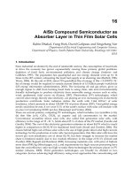
The most commonly known reconfigurable fixture is the conformable
clamping system developed by Cutkosky et al. for machining turbine-blade
forgings (Fig. 12). The two primary characteristics of this system are (1) the
use of variable-height (pneumatic) locators that fit the underneath profile of
the turbine blade along a line, and (2) the use of a flexible belt that wraps
around the upper profile of the turbine blade. The accurate positioning of
the line of support and the exact height determination of each one of the
FIGURE 11 T-slot and hole-based modular fixtures.
FIGURE 12 Conformable clamping system.
Chapter 11376
Copyright © 2003 by Marcel Dekker, Inc. All Rights Reserved.
locators must be carried out with great care. The use of a master template
has been proposed for this purpose.
An extension of the conformable clamping system from a 2-D line
support to a 3-D surface support could be achieved via a ‘‘bed of nails,’’
which would provide support to thick- and thin-walled surfaces. Such
custom-made fixtures have been used in the aerospace industry for the
drilling of thin-walled, large fuselage parts. Naturally, one may plan to use
only a partial set of ‘‘nails’’ (locators) that would provide sufficient rigidity.
The optimal number and locations of these locators can be determined using
finite-element-based stress analysis tools.
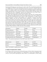
An important issue to consider in workholding for flexible manufac-
turing is the intelligence of the fixtures. In this context, there have been only
FIGURE 13 Intelligent locators for programmable fixtures.
Workholding—Fixtures and Jigs 377
Copyright © 2003 by Marcel Dekker, Inc. All Rights Reserved.
a limited number of attempts to incorporate sensors into workholding
devices in order to receive real-time feedback on the status of the fixturing
process. Two challenges in programmable (intelligent) fixture development
are (1) the detection of the accurate assembly of the reconfigurable fixture
components on the baseplate and (2) the subsequent detection of the
workpiece placement on the fixture and its clam ping. Both of these
challenges must be addressed without negatively affecting the accuracy of
locating and clamping the workpiece. A variety of such fixture components
were developed at the University of Toronto for a hole-based plate modular
fixturing system (Fig. 13). This fixture is able to detect the presence of
objects placed on it and activate clamps automatically for autonomous,
computer-based workholding.
11.4 COMPUTER-AIDED FIXTURE DESIGN
AND RECONFIGURATION
Fixture design for manufacturing may be a complex endeavor owing to
accuracy needs in an environment of nontrivial tool paths and, where
applicable, cutting forces. Commonly this task is carried out by an experi-
enced and skilled tool designer. Given a workpiece geometry and manufac-
turing conditions, the designer is required to develop the most suitable fixture
(dedicated or modular) and preferably a process plan for its fabrication. As
in any product design, the tool designer should utilize existing design
methodologies (Chaps. 3 and 4) and computer-aided-engineering (CAE)
analysis tools (Chap. 5) in the design and reconfiguration of fixtures/jigs.
The role of computer-aided design (CAD) varies according to the
fabrication strategy: for mass production, where dedicated fixtures would be
utilized for long periods of time, the emphasis would be on design, whereas
for small batch sizes or one-of-a-kind production, the emphasis would be on
the reconfiguration of the modular wor kholding setup. In both cases,
however, finite element analysis must be utilized for the prevention of
potential workpiece deflections due to fabrication forces.
11.4.1 Design of Fixtures/Jigs
The most basic approach to fixture design is the utilization of a CAD
package by a skilled tool designer for a design from scratch. The designer
builds the fixture around the CAD model of the workpiece using a graphical
user interface based on his or her past experience and knowledge of expected
fabrication conditions. Some commercial software packages provide design-
ers with a set of premodeled fixture components that they can retrieve from
the database and modify them as necessary.
Chapter 11378
Copyright © 2003 by Marcel Dekker, Inc. All Rights Reserved.
Group technology (GT) principles (Chap. 3) can be effectively utilized
in the fixturing of workpieces with geometric similarity. The objective is to
access fixture designs used in the past for workpieces that are similar to the
workpiece at hand. The retrieval of the most appropriate/useful (past)
fixture design can be achieved by the following sequential approach in a
CAD environment, where all workpiece geometric models have been
classified and coded:
1. Determine the GT code for the workpiece to be fixtured using the
company’s available classification and coding system.
2. Search the database of workpieces, for which there exist
corresponding fixtures/jigs, to determine the most similar (past) workpiece
geometry based on the GT code determined in Step 1.
3. Retrieve from the fixture database the (fixture) design correspond-
ing to the (past) workpiece identified in Step 2.
4. Evaluate whether the most similar past fixture design could be
effectively modified to yield a new design for the workpiece at hand. If the
answer is no, then, we must return to Step 2 in order to determine and
evaluate other similar designs, though the probability of finding a better past
fixture design would be low, if the coding and classification system has
functioned properly in the first iteration. After several evaluation iterations,
Steps 2 to 4, if a suitable past fixture design can still not be identified, the
designer must design a new fixture from scratch.If a retrieved fixture design is
deemed to be suitable, the process continues.
5. Access all past information stored in the database regarding the
past fixture design: reasoning behind the selection of specific locators/
supports/clamps, etc., as well as the evaluation metrics for the specific fixture
configuration chosen.
6. Modify the (retrieved) fixture design for the workpiece geometry
and fabrication conditions at hand. This step is an iterative process itself,
where different designs and configurations must be analyzed using CAE
analysis tools (Sec. 4.2 below).
7. Store the new workpiece and fixture models and other pertinent
data in their appropriate databases according to the GT code (of the new
workpiece) for future use.
The above sequential process can be utilized for the design of dedicated
fixtures as well as for the reconfiguration of modular fixtures.
There have been several attempts by academic investigators to
develop CAD-based tools for the automatic synthesis of fixture designs
(with almost no manual intervention). These systems utilize a variety of
reasoning techniques (including heuristics and analytical models) to deter-
mine locating and clamping points on the workpiece, choose corresponding
fixture component geometries, and assemble the fixture (in the CAD’s
Workholding—Fixtures and Jigs 379
Copyright © 2003 by Marcel Dekker, Inc. All Rights Reserved.
virtual environment) for subsequent interference checks. Generative fixture
design is another term used for such experimental design procedures.
11.4.2 Fixture Configuration and Analysis
Fixture configuration is commonly referred to as the process of determining
the positions of locators and clamps for modular fixtures. However, as
discussed earlier in this section, one must also select these positions with
great care in the case of dedicated (nonreconfigurable) fixtures. The objec-
tive is engineering analysis for optimal fixture configuration.
Due to time-varying forces acting on the fixture, the problem at hand
is a dynamic type, where fixture and workpiece behavior under loading must
be analyzed. The analysis is almost always carried out using (numerical)
finite element–based modeling owing to the complexity of workpiece
geometry. The optimization process attempts to vary the fixture configu-
ration in order to minimize deflections with preferred minimal clamping
forces. Fixture configuration includes the following (optimization) varia-
bles: the number, types, and positions of locators, supports, and clamps
and clamping forces. The problem is a mixed integer/continuous-variable
type and must be solved by employing an appropriate search method
(Chap. 5).
REVIEW QUESTIONS
1. Define workholding (fixturing) and state its primary objectives.
2. Define jigs versus fixtures.
3. Explain the 3-2-1 principle in workholding.
4. Why should locators be manufactured as entities separate from the
body of the fixture/jig?
5. Define locating versus clamping. Why should manufacturing forces be
directed toward support points and not be compensated by clamps
(i.e., directed toward clamps)?
6. Why should clamps be power activated (versus being manual)?
7. Is the design process of a fixture different from that of the part it is
manufactured to fixture? Explain.
8. Discuss the different classes of bushings available for jigs.
9. Discuss the use of tenons in the placement of fixtures onto machine
worktables.
10. Compare the principal requirements for machining fixtures versus
those for assembly fixtures.
11. Discuss the need for flexible fixtures in smal l-batch and/or one-of-a-
kind manufacturing environments.
Chapter 11380
Copyright © 2003 by Marcel Dekker, Inc. All Rights Reserved.
12. Compare modular fixtures versus reconfigurable/reprogrammable
fixtures.
13. Compare the use of hole-based base plates versus T-slot-based ones in
modular fixturing.
14. Why should fixtures/jigs be reprogrammable?
15. Discuss the use of computer-aided design (CAD) and engineering
analysis (CAE) tools in fixture design. In your discussion, also refer to
issues such as, group technology (GT), generative design, and so on.
DISCUSSION QUESTIONS
1. Discuss possible sensing technologies that can be incorporated into
different workholding devices for the on-line monitoring and con-
trol of the manufacturing process, while the parts are being fabri-
cated/assembled.
2. Fixtures can be designed for a specific range of metrics within the
targeted family of products: (1) Those that allow reconfiguration via
continuous and/or discrete incremental changes, or even through
modularity of certain subcomponents, or (2) those that have been
already manufactured in different dimensions, etc., for different product
dimensions. Discuss these modes of fixture design in terms of
manufacturing difficulties, durability, safety, cost, etc.
3. The use of design features has long been considered as improving the
overall synthesis and analysis stages of products owing to the potential
of encapsulating additional nongeometric data, such as process plans,
in the definition of such features. Discuss feature-based design, in which
the user, through some recognition/extraction process, can access and
retrieve individual similar or identical features on earlier product/
fixture designs and utilize them for the design of the fixture at hand.
4. Finite-element modeling and analysis (FEM/A) methods have been
developed to cope with the engineering analysis of complex product
geometries and/or physical phenomena. Discuss the use of FEA during
the (iterative) fixture design process (i.e., synthesis analysis) for the
determination of optimal design parameter values, for example in
verifying part deflections under clamping and/or manufacturing forces.
5. Fixturing is a typical design process that involves the iterative synthesis
and analysis stages, during which we would determine the optimal
support and clamping positions for a workpiece at hand and
accordingly configure, design and manufacture a mechanical fixture.
Due to high accuracy requirements, the cost of a complex fixture can
also be very high. This cost is normally amortized over a large number
of identical parts in mass production cases. Discuss the utilization of
Workholding—Fixtures and Jigs 381
Copyright © 2003 by Marcel Dekker, Inc. All Rights Reserved.
modular fixtures for small-batch and one-of-a-kind manufacturing
cases. Address issues such as accuracy of components, ease of assembly,
computer-aided planning of fixture configuration, and others.
6. Would several different GT based classification and coding systems be
needed in a company for different objectives? That is, one system for
product/fixture design, one system for manufacturing planning, and
yet another for cost engineering.
7. In the near future, although the majority of engineering products will
be modeled in the virtual (computer) space, representing the starting
point of the design and manufacturing process, some products will still
be crafted manually by artisans and/or industrial designers. Discuss
the computer-aided design and manufacturing of fixtures for such
products, whose features are not originally defined by exact
mathematical relationships.
8. Machining centers increase the automation/flexibility levels of machine
tools by allowing the automatic change of cutting tools via turrets or
tool magazines. Some machining centers also allow the off-line fixturing
of workpieces onto standard pallets, which would minimize the on-line
setup time (i.e., reduce downtime of the machine): that is, while the
machine is working on one part fixtured on Pallet 1, the next part can
be fixtured on Pallet 2 and loaded onto the machine when it is has
completed operating on the first part. Discuss the use of such universal
machining centers versus the use of single-tool, single-pallet, uni-
purpose machine tools.
9. Job shops that produce one-of-a-kind products have been considered
the most difficult environments to automate, where a product can be
manufactured within a few minutes or may require several days of
fabrication. Discuss the role of reconfigurable fixtures in facilitating
the transformation of such manual, skilled-labor dependent environ-
ments to intensive automation-based environments.
10. Manufacturing flexibility can be achieved at three levels: operational
flexibility, tactical flexibility, and strategic flexibility. Discuss opera-
tional flexibility. Is fixturing automation a necessary or a desirable tool
in achieving this level of flexibility?
BIBLIOGRAPHY
Benhabib, B., Chan, K. C., Dai, M. Q. (1991) A modular programmable fixturing
system. ASME Journal of Engineering for Industry 113(1):93–100.
Boyes, William E., ed. (1982). Jigs and Fixtures. Dearborn, MI: SME.
Boyes, William E. (1986). Jigs and Fixtures for Limited Production. Dearborn, MI:
SME.
Chapter 11382
Copyright © 2003 by Marcel Dekker, Inc. All Rights Reserved.
Chan, Ka-Ching (1989). Development of a Modular Programmable Fixturing
System for Assembly. M.A.Sc. thesis, Department of Mechanical Engineering,
University of Toronto, Toronto, Canada, 1990.
Chan, K. C., Benhabib, B., Dai, M. Q. (1990). A reconfigurable fixturing system for
robotic assembly. SME Journal of Manufacturing Systems 9(3):206–221.
Cutkosky, M. R., Kurokawa, E., Wright, P. K. (1982). Programmable, conform-
able clamps. SME AUTOFACT Confe rence Proceedings, Philadelphia, PA,
(11.51–11.58).
Drozda, Thomas, Wick, J. Charles, eds. (1998). Tool and Manufacturing Engineers
Handbook: A Reference Book for Manufacturing Engineers, Managers, and
Technicians. Society of Manufacturing Engineers, Dearborn, MI.
Gandhi, M. V., Thompson, B. S. (1986). Automated design of modular fixtures
for flexible manufacturing systems. SME Journal of Manufacturing Systems
5(4):243–252.
Henriksen, Erik Karl (1973). Jig and Fixture Design Manual. New York: New York
Industrial Press.
Hoffman, Edward G. (1980). Jig and Fixture Design. Albany, NY: Delmar.
Hoffman, Edward G. (1987). Modular Fixturing. Lake Geneva, WI: Manufacturing
Technology Press.
Nee, Andrew Y. C., Whybrew, K., Kumar, A. Senthil (1995). Advanced Fixture
Design for FMS. New York: Springer-Verlag.
Nee, John G., ed (1998). Fundamentals of Tool Design. Dearborn, MI: SME.
Pham, D. T., De Sam-Lazaro, A. (1990). AUTOFIX. An expert CAD system for jigs
and fixtures. Int. Journal of Machine Tools Manufacturing 30(3):403–411.
Rong, Yiming, Zhu, Yaoxiang (1999). Computer-Aided Fixture Design. New York:
Marcel Dekker.
Sela, M. N., Gaudry, O., Dombre, E., Benhabib, B. (1997). A reconfigurable mod-
ular fixturing system for thin-walled flexible objects. Int. Journal of Advancd
Manufacturing Technology 13(9):611–617.
Smith, Graham T. (1993). CNC Machining Technology: Volume 2, Cutting Fluids and
Workholding Technologies. New York: Springer-Verlag.
Thompson, B. S. (1984). Flexible fixturing—a current frontier in the evolution of
flexible manufacturing cells. ASME Proceedings of the Winter Annual Meeting,
84-WA/PROD-16, New Orleans, LA.
Workholding—Fixtures and Jigs 383
Copyright © 2003 by Marcel Dekker, Inc. All Rights Reserved.