Materials Science and Engineering - Electronic and Mechanical Properties of Materials Part 10 pps
Bạn đang xem bản rút gọn của tài liệu. Xem và tải ngay bản đầy đủ của tài liệu tại đây (327.56 KB, 10 trang )
4
3.225
7
© H.L. Tuller-2001
0 5 10 15 20 25 30 35
1E-5
1E-4
1E-3
0,01
0,1
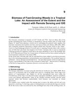
T = 850°C
X=0.03
X=0.03
Sr
1-x
La
x
TiO
3
porous ceramic
σ
/ S/cm
t / h
Transient Behavior of Porous Sr
1-x
La
x
TiO
3
for x=0.005 and x=0.03
T = 850 °C
3.225
8
© H.L. Tuller-2001
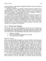
Mechanisms in Semiconducting Gas Sensor
• Interface - Gas adsorption
2e
’
+ O
2
(g) O(s)
’
Induce space charge barrier
1. Surface conduction
2. Grain boundary barrier
Grain boundary barrier
modulate
2=
3.225
9
© H.L. Tuller-2001
Sensor Configuration
A single 9 mm
2
chip sensor array with:
• four sensing elements with interdigitated structure electrodes
•heater
• temperature sensor
3.225
10
© H.L. Tuller-2001
Schematic Cross Section of Mounted Sensor
5
6
3.225
11
© H.L. Tuller-2001
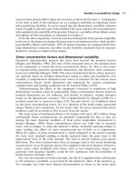
Resistance onse to Gas Environment
•
ZnO film (150 nm)
•
Electrode: Pt(200 nm)/Ta(25 nm) film
• Insulation layer: SiO
2
layer (1 µm)
• Substrate:
Si wafer
Si wafer
ZnO film
H
2
H
2
H
2
H
2
Pt electrode
SiO
2
layer
Electrical
Measurement
0 20 0 0 0
-10
0
10
20
30
40
50
60
70
80
90
100
110
-10
0
10
20
30
40
50
60
70
80
90
100
110
MFC2 Temp NO2 NH3
Feuchte CO NO2kl H2
Pt-100 resistance / Ω
Gas flow / sccm
time / h
0 20 0 0 0
100k
Temp:360C, H
2
, CO, NH
3
(10, 50 and 100 ppm), NO
2
(0.2, 0.4, and 2 ppm)
ZnO(Ar:O
2
=7:3) 1
[ Pfad: \ alp ha missy Messungen messplat z_1 ] M. Jägle / 27.02.2001
S1219a
S1219b
S1219c
S1219d
resistance / Ohm
M 9710746 20V
Datum: 23.02.2001 - 27.02.2001
Steuerdatei: allgas_h2.st g
Meßprotokoll: 273
Schematic of Gas Sensor Structure
3.225
12
© H.L. Tuller-2001
MicroElectroMechanical Systems - MEMS
Micromachining - Application of microfabrication tools, e.g. lithography, thin
film deposition, etching (dry, wet), bonding
Bulk Micromachining Surface Micromachining
Resp
4 6 8
4 6 8
3.225
13
© H.L. Tuller-2001
Gas Sensors and MEMS
• Miniaturization
• Reduced power consumption
• Improved sensitivity
• Decreased response time
• Reduced cost
• Arrays
• Improved selectivity
•Integration
•Smart sensors
3.225
14
© H.L. Tuller-2001
Microhotplate
7
3.225
15
© H.L. Tuller-2001
Microhotplate Sensor Platform
NIST Microhotplate Design
3.225
16
© H.L. Tuller-2001
Microhotplate Characteristics
• Milli-second thermal rise and fall times
programmed thermal cycling
low duty cycle
• Low thermal mass
low power dissipation
• Arrays
enhanced selectivity
8
3.225
17
© H.L. Tuller-2001
Harsh Environment MEMS
•
High temperatures
• Oxidation resistant
• Chemically inert
• Abrasion resistant
Wide band gap semiconductor/insulator
3.225
18
© H.L. Tuller-2001
Photo Electro-chemical Etching - PEC
•
materials versatility
e.g. Si, SiC, Ge, GaAs, GaN,
etc.
• precise dimensional control down to 0.1 mm
through the use of highly selective
p-n junction
etch-stops
• fabrication of structures with
negligible internal
stresses
• fabrication of structures
not constrained by
specific crystallographic orientations
Features:
9
3.225
19
© H.L. Tuller-2001
+
-
+
-
h
+
h
+
h
+
h
+
semiconductor
Photo Electro-chemical Etching - PEC
• Electro-chemical
etching
p-type
+
-
Light source
• Photo electro-
chemical etching
+
-
h
+
h
+
semiconductor
electrolyte
Light source
n-type
3.225
20
© H.L. Tuller-2001
Examples
•
Arrays of stress free
4.2 µm thick cantilever
beams.
•
Photoelectrochemically
micromachined cantilevers
are
not constrained
to
specific crystal planes or
directions.
•
Similar structures
successfully
micromachined from SiC
by Boston MicroSystems
personnel
10
3.225
21
© H.L. Tuller-2001
Smart Gas Sensor
A Self Activated Microcantilever-based Gas Sensor
1. A device capable of sensing a change in environment and
responding without need for a microprocessor
2. A device has both gas sensing and actuating function by
integration of semiconducting oxide and piezoelectric thin films.
Micro-
Processor
Actuator
Sensor
Chemical
Environment
Microfluidic structure
3.225
22
© H.L. Tuller-2001
Smart Gas Sensor
1. Semiconducting oxide thin films for high gas sensitivity
:
Microstructure (Nano-Structure) and Composition
2. Piezoelectric thin films for providing actuating function
3. Thin film electroceramic deposition methods for integrating with
silicon microcantilever beam
:
Compatibility with Si micromachining technology
4. Microcantilever structures for the self activated gas
:
High performance in chemical environment
sensor
11
3.225
23
© H.L. Tuller-2001
Resonant Gas Sensor
• Resonant Frequency:
f
R
= 1/2l (
µ
o
/
ρ
o
)
1/2
where
l
= resonator thickness,
µ
o
= effective shear modulus and
ρ
o
=
density
• Mass change causes shift in resonant frequency :
(m
0
-
∆
m) / m
o
≈
(f +
∆
f) / f
Gas Sensor elements :
(I)
Active layer
interacts with environment
- stoichiometry change translates into mass change
(II)
Resonator
transduces mass change into resonance frequency change
∆
f
∆
m
Electrode
Electrode
Resonator
Active layer
3.225
24
© H.L. Tuller-2001
Choice of Piezoelectric Materials
• Temperature limitations of piezoelectric materials
Material Max Operating
Tem
p
erature
(
o
C
)
Limitations
Quartz 450 High loss
LiNbO
3
300 Decomposition
Li
2
B
4
O
7
500 Phase transformation
GaPO
4
933 ? Phase transformation
La
2
Ga
5
SiO
4
(Langasite)
1470 ? Melting point
12
3.225
25
© H.L. Tuller-2001
Design Considerations
•
Bulk conductivity
dependent on temperature and PO
2
→ contributes to resonator electrical losses
Modify bulk conductivity - how?
•
Stability
to oxidation and reduction process
→ limited oxygen non-stoichiometry
→ slow oxygen diffusion kinetics
Defect chemistry and diffusion kinetics study
•
f
R
(T)
: Temperature dependence of resonant frequency
→ need to differentiate from mass dependence
Minimize @ intrinsic and device-levels
3.225
26
© H.L. Tuller-2001
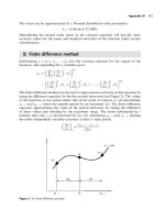
Langasite : Bulk Electrical Properties
• Single activation energy in the temperature range 500 -
900 °C
• Extrapolated room temperature conductivity: σ = 4.4×10
-18
S cm
-1
8 9 10 11 12 13
10
-7
10
-6
10
-5
10
-4
Y-cut
σ
0
= 2.1 S cm
-1
E
A
= 105 kJ mol
-1
10
4
/T [1/K]
σ
[S cm
-1
]
900 800 700 600 500
T [°C]
13