BARRIER SYSTEMS for ENVIRONMENTAL CONTAMINANT CONTAINMENT and TREATMENT - PART 3 pptx
Bạn đang xem bản rút gọn của tài liệu. Xem và tải ngay bản đầy đủ của tài liệu tại đây (1.78 MB, 65 trang )
143
3
Material Stability
and Applications
Prepared by*
Craig H. Benson
University of Wisconsin at Madison, Madison,
Wisconsin
Stephan F. Dwyer
Sandia National Laboratories, Albuquerque,
New Mexico
3.1 OVERVIEW
This chapter focuses on material properties and behavior for caps, cutoff walls,
and permeable reactive barriers (PRBs), with an emphasis on understanding the
mechanisms and factors that affect their durability in full-scale systems. Infor-
mation obtained from laboratory tests are analyzed in this context. The reader is
referred to the preceding book in the containment series, Assessment
of
Barrier
Containment
Technologies
(Rumer and Mitchell, 1995), as well as Daniel (1993),
Gavaskar et al. (1998), LaGrega et al. (2000), Blowes et al. (2000), Naftz et al.
(2002), and Reddi and Inyang (2000) for detailed information on the general
characteristics of barrier materials mix design approaches and performance issues.
In this chapter, the emphasis is on fundamental factors and laboratory and field
observations that relate to the long-term performance of materials used in con-
structing various types of containment systems. The overall performance of these
systems has been analyzed holistically using the systems approach in Chapter 1.
Chapter 2 dealt with models of water and contaminant fate and transport through
components of containment systems. It is herein recognized that material properties
* With contributions by David W. Blowes, University of Waterloo, Waterloo, Ontario, Canada; David
A. Carson, U.S. Environmental Protection Agency, Nashville, Tennessee; Peter W. Deming, Mueser
Rutledge Consulting Engineers, New York, New York; Jeffrey C. Evans, Bucknell University, Lewis-
burg, Pennsylvania; Glendon W. Gee, Battelle Pacific Northwest National Laboratory, Richland,
Washington; Hilary I. Inyang, University of North Carolina at Charlotte, Charlotte, North Carolina;
Stephan A. Jefferis, University of Surrey, Surrey, United Kingdom; Mark R. Matsumoto, University
of California at Riverside, California; Gustavo Borel Menezes, University of North Carolina at
Charlotte, Charlotte, North Carolina; Stanley J. Morrison, Environmental Services Laboratory, Grand
Junction, Colorado; Scott D. Warner, Geomatrix Consultants, Oakland, California; John A. Wilkens,
DuPont, Wilmington, Delaware
4040_C003.fm Page 143 Wednesday, September 21, 2005 12:29 PM
© 2006 by Taylor & Francis Group, LLC
144 Barrier Systems for Environmental Contaminant Containment & Treatment
play a significant role in overall system performance. This chapter is divided into
three primary subsections, each of which addresses materials performance for a
specific type of containment structure.
3.1.1 THE ROLE OF BARRIER MATERIAL MINERALOGY AND MIX
COMPOSITION ON PERFORMANCE
Earthen materials or geomaterials are the most frequently used materials in
containment system barrier construction. Generally, barrier mixes are composites
of particles of various sizes and minerologies. For barriers that are designed to
minimize flow rates and retard contaminant solute transport through physico-
chemical interactions, clays are commonly used in mixes with silts; sands; and
amendments such as resins, activated carbon, slags, polymers, and ash. The clays
are usually alumino-silicates native to the barrier material, or they may be added
to the barrier mix in cases where the natural clay content of the barrier material
is insufficient to provide the required mix characteristics. In other cases, barrier
materials are fabricated and used to provide specific functions. An example is a
geomembrane that can be incorporated as a component into a containment structure
for fluid retention, separation of clay to minimize the chance of attack by aggres-
sive permeants, and diversion of gas flow to desirable control points. Table 3.1
provides a general listing of various characteristics of barriers that affect classes
of phenomena that relate to the most significant barrier design objectives. Some of
TABLE 3.1
Containment System Design Considerations and Material
Characteristics that are Usually Evaluated in Bench-Scale Tests
Physico-Chemical
Design Consideration Phenomena of Concern
Significant Barrier
Material Properties
Reduction of
contaminant release
and transport
Advection Hydraulic conductivity
Density
Moisture content
Gradation
Porosity
Crack density
Diffusion Porosity
Dispersion Tortuosity
Leachability Crack density
Chemical compatibility Inadequate retardation Density
Physical durability Chemical attack Mineralogy relative to
contaminant chemistry
Radiation transport Density, mass attenuation
coefficient
4040_C003.fm Page 144 Wednesday, September 21, 2005 12:29 PM
© 2006 by Taylor & Francis Group, LLC
Material Stability and Applications 145
the barrier parameters such as hydraulic conductivity, porosity, and crack density
apply to compacted, cemented, and fabricated materials.
For granular barrier materials that may be compacted or cemented into barrier
layers, the component material mineralogy and specific surface area are key
material factors that, in combination with the emplacement density, control the
initial and long-term barrier material textures when exposed to physical stresses
and chemical contact. Mineralogy controls the physico-chemical interactions
(including the reactivity) of a barrier component with permeating fluids under a
given environmental condition. Under the most frequently encountered temper-
ature, pressure, and pH–Eh conditions in the field, clays (comprising mostly
aluminosilicates) react with permeants much more aggressively than sands (com-
prising mostly silica). Because of their mineralogy, the charged clay surfaces
present opportunities for the chemisorption of charged contaminants such as
heavy metals as summarized by Inyang (1996) in Table 3.2.
For a barrier material that has favorable mineralogy (i.e., a mineralogy that
favors its interaction with permeating fluids in reactions that remove solutes
without degrading the barrier), the opportunity for its interaction with the per-
meant is enhanced if its specific surface is high. The specific surface is the ratio
of surface area to weight of a material, and it is inversely proportional to the
grain size of the material. For surface reactions like cation exchange and adsorp-
tion that are prevalent in barriers, their role in increasing the contaminant distri-
bution coefficients (i.e., cleaning the permeating fluid in terms of its entry vs.
exit chemistries) increases as the specific surface of the component material
increases, as reflected in results plotted by Milne-Home and Schwartz (1989)
presented in Figure 3.1. Often, even when a specific barrier component exhibits
a desirable material characteristic, it may not be adequate with respect to another
characteristic. For example, a clay mineral such as sodium montmorillonite may
be sorptive enough for heavy metals but inadequate in terms of providing strength
against desiccation. Yet still, cost considerations usually preclude the use of
single-component barrier systems in waste containment. Essentially, most barrier
materials are composites, the proportions of which are designed to optimize
performance characteristics at minimal cost. In the case illustrated in Figure 3.2,
D’Appolonia (1980) evaluated the effects of fines (% minus #200 sieve) on the
permeability of soil-bentonite (SB) backfill candidate materials and found that
for both plastic fines and nonplastic/low-plasticity fines, the permeability
decreased as the fines content increased. Permeability values for the plastic fines
were generally lower than those of the nonplastic/low-plasticity fines. Presumably,
the plastic fines comprise more moisture-sensitive or expansive minerals than the
nonplastic/low-plasticity fines. Figure 3.3 shows the effects of bentonite (mont-
morillonite) content on the permeability of the SB backfill candidate material
mixes. A bentonite content of 3% (by dry weight) was adequate to reduce the
permeability values from 5 ×
10
–5
to 5 ×
10
–3
centimeters per second (cm/s) to
about 10
–7
cm/s for well-graded coarse materials.
In another investigation that illustrates the optimization of mix composition
to obtain a favorable material characteristic, Ryan and Day (1986) evaluated the
4040_C003.fm Page 145 Wednesday, September 21, 2005 12:29 PM
© 2006 by Taylor & Francis Group, LLC
146 Barrier Systems for Environmental Contaminant Containment & Treatment
TABLE 3.2
Sorption Characteristics of Soil Minerals and Chemical Additives
for Hazardous and Radioactive Metals
Single
Component
Material
General
Properties
Metals
Tested
Test
Type
Test
Conditions Results
Montmorillonite
(Garcia-
Miragaya and
Page, 1976)
CEC =
94.8 meql/L;
particle size
<2 µ
m
Cd
2+
Batch Initial pH
range =
4.6–7.3
95%, 95%, and 90%
of Cd
2+
sorbed by
Na-, Ca-, and
K-montmorillonite,
respectively
Montmorillonite
from Texas
(Puls and
Bohn, 1988)
Ca —
saturated
Cd
2+
, Zn
2+
,
Ni
2+
Batch Initial pH =
5.5, 6.5, 7.5
50% of metals were
adsorbed at pH
range of 4–5.81
Vermiculite
(Ziper et al.,
1988)
K — fixed,
500–1000
µ
m particle
size, SSA =
22.5 m
2
/g
Cd
2+
Batch Initial pH =
5.0, 10
–9
–10
–5
M
0.9 moles of Cd
2+
adsorbed per kg
Kaolinite
(Puls and
Bohn, 1988)
Fine particles Cd
2+
, Zn
2+
,
Ni
2+
Batch Initial pH =
5.5, 6.5, 7.5
Adsorption followed
the order: Cd >
Zn > Ni. 50% of
metals were
adsorbed within pH
range 4.49–5.80
Kaolinite (Yong
and Galvez-
Cloutier, 1993)
LI = 61%,
SSA =
24 m
2
/g;
84% below
2 µ
m
Pb
2+
Batch Initial pH =
3.0. 4 g of
Kaolinite in
40 mL of lead
solutions
Maximum Pb
2+
adsorption
decreased at high
pH due to
precipitation
Goethite
(iron oxide)
(Coughlin and
Stone, 1995)
SSA =
47.5 m
2
/g
Mn
2+
, Co
2+
,
Ni
2+
, Cu
2+
,
Pb
2+
Batch Initial pH =
3–8. NaNO
3
used to
maintain
selected ionic
strength
Coordination
chemistry of oxides
affects adsorption.
50% of Cu
2+
, Pb
2+
,
Co
2+
, Ni
2+
removed
at pH 4.5, 4.8, 6.3,
6.8, respectively
Goethite
(iron oxide)
(Kuo, 1996)
Zn
2+
, Cd
2+
,
Ca
2+
Batch Initial pH =
5.3–8.3.
NaNO
3
used
to maintain
selected ionic
strength
Selectivity order:
Zn
2+
> Cd
2+
> Ca
2+
4040_C003.fm Page 146 Wednesday, September 21, 2005 12:29 PM
© 2006 by Taylor & Francis Group, LLC
Material Stability and Applications 147
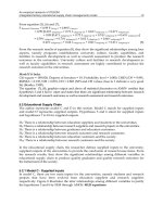
permeability ranges of three mix compositions for a fly ash cement-slurry wall,
the results of which are presented in Figure 3.4. Test results developed (Fleming
and Inyang, 1995) for fly ash amended materials, which may, in some cases,
exhibit cementation if the ash mineralogy is favorable or some cementing agents
are added, show that initial and longer term permeabilities of cemented barrier
materials can be significantly influenced by reactions among the mix components.
Figure 3.5 shows the conceptual textural patterns proposed by Fleming and Inyang
(1995) in a comparative study of the effects of class F (nonreactive) fly ash and
class C (reactive) fly ash amendment of barrier clay on changes in permeability
under freeze-thaw action. The patterns are similar, but the reactive fly ash exhibits
initial and final permeabilities that are lower than those of the nonreactive ash.
3.1.2 APPROACHES TO MATERIAL EVALUATION AND SELECTION
Bench-scale tests provide the best opportunity to evaluate the fundamental char-
acteristics of barrier materials. However, holistic assessments of a barrier system
performance are most meaningfully performed through a combination of bench-
scale testing and field quality assurance and monitoring tests. The bench-scale
approach has been widely used to evaluate barrier material parameters in batch
TABLE 3.2 (continued)
Sorption Characteristics of Soil Minerals and Chemical Additives
for Hazardous and Radioactive Metals
Single
Component
Material
General
Properties
Metals
Tested
Test
Type
Test
Conditions Results
Fly ash (Singer
and Berkgaut,
1995)
Hydrothermal
ly treated,
CEC =
2.5–3 meq/g
Pb
2+
, Sr
2+
,
Cu
2+
, Zn
2+
,
Cd
2+
, Cs
2+
Batch Initial pH =
5.0. Total
concentration
of competing
ions = 0.1 N
Selectivity order:
Pb
2+
> Sr
2+
> Cu
2+
> Cd
2+
> Zn
2+
>
Cs
2+
at 25 mg/L
lead concentration,
absorbed Pb =
35 µ
g/g
Pyrolusite
(MnO
2
) (Ajmal
et al., 1995)
Crushed
samples
Pb
2+
, Cd
2+
,
Zn
2+
, Mg
2+
Batch Washed and
dried at
40°
C; pH
range of
about 2–8
At pH = 6.5, 100%
of initial 22.7 mg/L
of Pb
2+
was sorbed;
other results show
high sorption for
Zn
2+
and Cd
2+
but
low sorption for
Mg
2+
Source:
Inyang, H.I. (1996). Sorption of inorganic chemical substances by geomaterials and additives,
Report CEEST/001R-96, University of Massachusetts, Lowell, MA.
4040_C003.fm Page 147 Wednesday, September 21, 2005 12:29 PM
© 2006 by Taylor & Francis Group, LLC
148 Barrier Systems for Environmental Contaminant Containment & Treatment
systems, monoliths of scaled down dimensions, or columns of media. The latter
can be densely compacted, as in the case of earthen materials considered for
fluid/contaminant transport barriers or loosely emplaced as in reactive columns.
Most of the granular barrier material characteristics that are usually targeted are
summarized in Table 3.3. Not all of these tests need to be performed for all barrier
materials. Some tests, exemplified by porosimetry, are not usually performed
because the influence of the pore size distribution measured is represented along
with barrier material density and reactivity with specific contaminants in data
obtained from column tests for contaminant retardation coefficient estimation.
The tests listed in Table 3.3 have designations that vary from one country to
another, although they are most standardized under the American Society for
FIGURE 3.1
Specific surface vs. bulk cation exchange capacity for various sediments
and minerals. (From Milne-Home, W.A. and Schwartz, F.W., 1989. Proceedings of the
Conference on New Field Techniques for Quantifying the Physical and Chemical Proper-
ties of Heterogeneous Aquifers, Dallas, Texas, pp. 77–98. With permission.)
Specific surface (m
2
/g.)
1000
100
10
1
0.1
0.1 1
Bulk C.E.C. (meq/100 g)
10 100
Montmorillonite
Illite
Kaolinite
Explanation
American Petroleum Institute
Reference clays (Patchett, 1975)
Shales (Patchett, 1975)
Milk River formation
Mome L’Enfer, Erin formations
Belly River formation (GENPAR 2)
Sandstones
Discrete particle clays
Pore ilning clays
Pore bridging clays
1
1
2
3
1
1
1
1
2
2
2
2
2
3
3
3
3
4040_C003.fm Page 148 Wednesday, September 21, 2005 12:29 PM
© 2006 by Taylor & Francis Group, LLC
Material Stability and Applications 149
rials such as geomembranes are tested under protocols that are different from
those of granular barrier materials. Fundamental tests are important because they
can provide data that are helpful in performing a general durability evaluation of
barrier materials and understanding mechanisms that are determinants of their
durability.
3.1.3 GEOSYNTHETICS AND THEIR DURABILITY IN BARRIER SYSTEMS
In general, the ability of barrier materials to retard fluid transport, resist chemical
and biological attack, and maintain structural integrity under externally imposed
stresses depends on their composition, emplaced thickness, and the quality assur-
ance practices implemented during construction. Early in the development of
containment system design configurations, earthen and cementitious barrier mate-
rials were used almost exclusively. A more recent development, particularly
within the past two decades, is an increase in the use of geosynthetic materials
to enhance containment system barrier layer performance. Both earthen and
geosynthetic barrier materials have advantages and disadvantages. Earthen bar-
riers are most commonly clayey soils that are either compacted into layers as in
landfills and surface impoundments or emplaced as slurry backfill as in slurry
cutoff walls. While they can retard contaminant transit through a variety of
processes (e.g., sorption, induced precipitation of dissolved substances within
inter-particle pore spaces), significant variability and uncertainty can exist in the
FIGURE 3.2
Effects of fines content on the permeability of soil-bentonite backfill. (From
D’Appolonia, 1982. Proceedings of the 13th Annual Geotechnical Lecture Series, Phila-
delphia Section
, American Society of Civil Engineers, Philadelphia, PA. With permission.)
% Minus #200 sieve
80
70
60
50
40
30
20
10
0
10
−4
10
−5
10
−6
10
−7
10
−8
10
−9
Plastic
fines
SB Backfill permeability, cm/sec
Nonplastic or low
plasticity fines
4040_C003.fm Page 149 Wednesday, September 21, 2005 12:29 PM
© 2006 by Taylor & Francis Group, LLC
Testing Materials (ASTM) protocols. As evident in Section 3.2, fabricated mate-
150 Barrier Systems for Environmental Contaminant Containment & Treatment
spatial distribution of barrier transport parameters such as hydraulic conductivity
and diffusion coefficient. Furthermore, under aggressive chemical environments
and sustained desiccation processes, earthen barriers can develop enlarged flow
channels that allow contaminants in both the gaseous and liquid phases to travel
through the barrier easily. Geosynthetic materials such as geomembranes have less
FIGURE 3.3
Effects of bentonite content on the permeability of SB backfill. (From
D’Appolonia, 1982.
Proceedings of the 13th Annual Geotechnical Lecture Series, Phila-
delphia Section, American Society of Civil Engineers, Philadelphia, PA. With permission.)
FIGURE 3.4 The effects of cement/water ratio and fly ash/cement ratio on the perme-
abilities of slurry wall mixtures. (From Ryan, C.R. and Day, S.R., 1986. Proceedings of
the 7
th
National Conference on Management of Uncontrolled Hazardous Waste Sites,
Washington, DC. With permission.)
Permeability of SB backfill, cm/sec.
10
–2
10
–3
10
–4
10
–5
10
–6
10
–7
10
–8
10
–9
0 1 2
% Bentonite by dry weight of SB backfill
3 4
5
Well-graded coarse
gradations (30–70% + 20 sieve)
w/10 to 25% nonplastic fines
Poorly graded silty sand
w/30 to 50% nonplastic fines
Clayey silty sand
w/30 to 50% fines
Mix 3
Mix 2
Mix 1
10
–7
10
–6
K, (cm/sec.)
C/W FA/C
Mix 1 0.20 0.00
Mix 2 0.20 0.24
Mix 3 0.25 0.60
10
–5
Average
(typ.)
4040_C003.fm Page 150 Wednesday, September 21, 2005 12:29 PM
© 2006 by Taylor & Francis Group, LLC
Material Stability and Applications 151
variability in the spatial distribution of transport parameter magnitudes because
they are manufactured in tightly controlled processes. Furthermore, they are less
permeable to fluids and offer the opportunity to minimize the overall design
thickness of a barrier layer. On the other hand, punctures, poor joints, and internal
degradation can diminish their effectiveness as barrier layers. Giroud et al. (1992,
1997) have developed quantitative methods for estimating liquid transport through
geomembrane defects.
Geosynthetic barrier materials have been used as barrier layers that comple-
ment the functions of earthen barrier layers. Many composite cover designs such
FIGURE 3.5
Effects of reactions among barrier constituents on the permeability of ash-
modified clayey barrier soil subjected to freeze-thaw cycling. (From Fleming, L.N. and
Inyang, H.I., 1995. ASCE Journal of Materials in Civil Engineering,
7(3), 178–182. With
permission.)
Before freezing
After freeze - thaw cycling
a. Class F fly
ash-modified clay soil
c. Class F fly
ash-modified clay soil
Permeability
b. Class C fly
ash-modified clay soil
d. Class C fly
ash-modified clay soil
Longitudinal fracture
Reactive ash particle
Clay platelet
Reacted rim
Nonreactive ash
particle
P
CA
P
OA
P
CB
0
t
CB
No. of freeze-thaw cycles or time
t
CA
P
OB
4040_C003.fm Page 151 Wednesday, September 21, 2005 12:29 PM
© 2006 by Taylor & Francis Group, LLC
152 Barrier Systems for Environmental Contaminant Containment & Treatment
as those consistent with the minimum design standards developed for the
Resource Conservation and Recovery Act (RCRA), comprise both soil barrier
layers and geosynthetic materials. Othman et al. (1997) have performed studies
of the performance of such barrier configurations in the field. The results indicate
that with adequate quality control, such systems can perform effectively, at least
within the few decades that they have been in service. Another composite barrier
system that typically produces desirably low hydraulic conductivities in barrier
systems is the geosynthetic clay liner (GCL) that has been studied by many
researchers (Estornell and Daniel, 1992; Rad et al., 1994; and Petrov et al., 1997).
The GCL is gaining wider acceptance in the containment industry because of its
cost effectiveness, relatively easy installation, and low barrier thickness. Instal-
Although test protocols, design methods, and quality assurance methods have
been developed [Koerner and Daniel, 1997; Haxo, 1987; United States Environ-
mental Protection Agency (USEPA), 1985], concerns about the long-term dura-
bility of geosynthetic materials in barrier systems remain. This concern is driven
by the knowledge that all materials that are exposed to stressors degrade with
time. Such degradation in the long term is not limited to geosynthetic materials,
but extends to emplaced earthen barrier materials as well. For geosynthetic
TABLE 3.3
General Testing Approaches and Methods for Significant
Characteristics of Batch and Compacted Barrier Materials
Dependent Property Test Method(s)
Soil Texture
Density
a
Direct measurement
Dispersivity Indeterminate; evaluate experimentally
Gradation Sieve, hydrometer tests
Hydraulic conductivity
a,b
Permeameter tests
Moisture content Drying tests
Path length/tortuosity
a
Indeterminate; evaluate experimentally
Plasticity
b
Atterberg limits
Pore size distribution Porosimetry
Porosity (effective)
a
Empirical methods, porosimetry
Soil Composition
Chemical (elemental) composition Chemical tests (e.g., x-ray fluorescence)
Mineralogy (crystallinity) Mineralogy tests (e.g., x-ray diffraction)
a
Denotes a property dependent on compaction.
b
Denotes a property dependent on mineralogy.
Source:
Adapted from Inyang, H.I. et al. (1998). Physico-Chemical Interactions
in Waste Containment Barriers, Encyclopedia of Environmental Analysis and
Remediation,
Vol. 2, Wiley, New York, pp. 1158–1165.
4040_C003.fm Page 152 Wednesday, September 21, 2005 12:29 PM
© 2006 by Taylor & Francis Group, LLC
lation methods are summarized in Section 3.4.3.
Material Stability and Applications 153
materials that have been effectively installed, degradation mechanisms include
aging, chemical attack, and photo-oxidation. To assess the potential effectiveness
of geosynthetic barriers in containment systems over 500 service time frames,
Badu-Tweneboah et al. (1999) analyzed prospective effects of various degradation
processes of a 1.5-millimeter (mm)-thick high-density polyethylene (HDPE)
geomembrane that was installed within a landfill cover. They used data from
studies performed on geomembranes and other polymeric materials to evaluate
the damage potential under sustained contact with aging agents such as oxygen,
microorganisms, heat, ultraviolet radiation, and radioactivity, as well as flaw
development due to abrasion, thermal stresses, animal burrowing, and plant root
penetration. The analysis led to the conclusion that up to 5% reduction in yield
strain can occur per 25 years of service, resulting in an estimated yield strain of
zero if a liner deterioration pattern is assumed or 36% of the original yield strain
in 500 years if a logarithmic deterioration pattern is assumed.
On the basis of their analysis, Badu-Tweneboah et al. (1999) estimated that
the progressive stiffening of the geomembrane due to molecular rearrangement
under induced stresses in common containment system configurations would
likely result in stress cracking after 300 years of service. The challenge is to
relate the damage potential to flaw sizes and numbers — a necessary step for
estimating potential fluid transport rates through geosynthetic materials.
3.2 MATERIAL PERFORMANCE FACTORS IN CAPS
Caps or surface barriers in general are used to isolate buried wastes or contam-
inated soils from the atmosphere and biota on the earth’s surface. To design an
effective cap, it is necessary to consider multiple objectives, including biota
intrusion (i.e., intrusion of plants, animals, and humans into the underlying waste
or contaminated soils), wind and water erosion, gas control, and percolation of
water into underlying waste. The material performance criteria established for
each of these objectives depend on the type of waste to be contained and the
risks imposed by the waste on the nearby environment. For example, stringent
mix design criteria may need to be used for facilities containing long-lived and
toxic radioactive wastes, whereas less stringent criteria can be applied to facilities
containing largely inert construction and demolition wastes. The life span over
which the cap must function is generally associated with the type of waste as
well (e.g., 1,000 years for radioactive wastes or 30 years for solid wastes). In
most containment applications, however, there is no intent of ever exhuming the
waste. Thus, a cap must meet the performance criteria as long as the material
being contained poses a risk to the surrounding environment. In most cases, this
means that caps need to be designed for perpetuity and that a plan be in place to
monitor and maintain the cap as needed.
Percolation from the base of the cap is the primary design criterion in most
cases. A capping approach that will meet a percolation criterion (e.g., <1 mm/year)
is usually selected. Then, the materials and geometry (e.g., layering) are selected
and configured to meet the percolation criterion, as well as the other criteria
4040_C003.fm Page 153 Wednesday, September 21, 2005 12:29 PM
© 2006 by Taylor & Francis Group, LLC
154 Barrier Systems for Environmental Contaminant Containment & Treatment
(e.g., erosion, biota intrusion, gas control). Two general cap designs are used:
resistive designs and water balance designs. Examples of resistive designs are
shown in Figure 3.6; examples of water balance designs are shown in Figure 3.7.
Resistive designs employ a barrier system with high hydraulic impedance to limit
percolation (Benson, 2001). The barrier system can consist of geomembranes,
fine-grained earthen materials, asphalt layers, or combinations of these or similar
materials. A drainage system is often used to limit the driving head on the barrier
and ensure physical stability. The water balance approach employs the store and
release principle to limit percolation to an acceptable amount (Benson, 2001).
Materials are selected that have adequate capacity to store infiltrating water during
wet periods without appreciable percolation. Vegetation is used to remove the
stored water and return it to the atmosphere so that the cover has the capacity to
store water during subsequent infiltration events.
The resistive and water balance design approaches are fundamentally different.
The resistive design approach is predicated on constructing and maintaining a
system that blocks natural water movement. In contrast, the water balance approach
FIGURE 3.6 Profiles of caps relying on a resistive barrier: (a) Compacted clay barrier
and (b) composite barrier.
Vegetated surface layer (150 mm)
Clay liner (>600 mm)
Clay liner (>600 mm)
(a)
(b)
Geomembrane
Geocomposite drain
Vegetated surface layer (150 mm)
4040_C003.fm Page 154 Wednesday, September 21, 2005 12:29 PM
© 2006 by Taylor & Francis Group, LLC
Material Stability and Applications 155
uses natural processes to limit natural water movement. The natural approach used
for water balance covers is considered by some to be superior. The logic is that
a system that works with nature (i.e., water balance cap) is believed to be less
likely to fail over the long term than a system that works against nature
(i.e., resistive cap). However, currently there is no direct evidence demonstrating
that one approach is superior, provided that the cap is designed and constructed
properly.
3.2.1 MATERIAL PERFORMANCE FACTORS IN COMPOSITE BARRIERS
Resistive designs generally employ engineered materials to provide the hydraulic
impedance needed to meet a percolation criterion. These materials include com-
pacted natural clays, bentonites used alone in layers (e.g., as in a geosynthetics
clay liner) or mixed with other earthen materials (e.g., a compacted mixture of
sand and bentonite), polymeric sheets known as geomembranes, and asphalt and
asphalt concrete layers (Koerner and Daniel, 1997). During the last decade, a
wealth of experience has accrued regarding the characteristics of these materials
and the elements that are required to reduce percolation to small amounts. Expe-
rience has shown that systems that rely solely on an earthen barrier (i.e., compacted
FIGURE 3.7 Schematic water balance caps: (a) Monolithic cap design and (b) two-layer
capillary barrier.
Finer-grained
soil
Coarser-grained
soil
Capillary
break
(b)
ick layer of
finer-grained
soil
Waste
(a)
4040_C003.fm Page 155 Wednesday, September 21, 2005 12:29 PM
© 2006 by Taylor & Francis Group, LLC
156 Barrier Systems for Environmental Contaminant Containment & Treatment
clay barrier or GCL) are prone to failure, even after short service lives, whereas
composite designs that combine a geomembrane underlain by an earthen barrier
appear to function extremely well, at least for the relatively short experience record
(<10 years) that currently exists (Benson, 2001, 2002). The performance of caps
that rely solely on a geomembrane or asphalt layer is largely unknown.
The following two examples illustrate how resistive designs that rely solely
on an earthen barrier can fail soon into their service lives. One is a cap employing
a compacted clay barrier consisting of 460 mm of compacted clay placed on
compacted subgrade and overlain with 150 mm of topsoil vegetated with Bermuda
and rye grasses. This type of cap is often the presumptive remedy (i.e., the default
design) for sites in the United States Superfund program, as was the case for the
cap described here. The other is a similar design, except a GCL was used instead
of a compacted clay barrier, and 600 mm of “protective cover soil” was placed
between the GCL and the topsoil layer. The topsoil layer was vegetated with
crown vetch to minimize erosion.
The clay barrier was compacted in a manner that yielded a field hydraulic
conductivity of 5 x 10
–8
cm/s at the time of construction (the design criterion was
10
–7
cm/s). The cap was intended to transmit less than 30 mm/year of percolation.
Concerns about long-term cap performance led to installation of a system for
monitoring all components of the water balance (Benson, 2002; Roesler et al.,
2002) and, most importantly, the percolation rate. Water balance data collected
from the cap since the time of construction are shown in Figure 3.8.
FIGURE 3.8 Water balance data for the clay cap.
0
500
1000
1500
2000
50
100
150
200
250
8/1/02
Surface runoff
Soil water
storage
No
rain
Drying
soil
Water applied, evapotranspiration,
surface runoff, and percolation (mm)
Soil-water storage (mm)
Evapo-transpiration
Percolation
Applied water
4/1/00 8/1/00 12/1/00 4/1/01 8/1/01 12/1/01 4/1/02
4040_C003.fm Page 156 Wednesday, September 21, 2005 12:29 PM
© 2006 by Taylor & Francis Group, LLC
Material Stability and Applications 157
Approximately 10 months after construction (September/October 2000), a
period with little precipitation persisted for approximately six weeks. During this
period, the cap desiccated as evidenced by the monotonic decrease in soil-water
storage during this period. Prior to this period, the cap transmitted percolation at
rate of approximately 30 mm/year, which is consistent with the design criterion.
Afterward, the percolation rate was approximately 500 mm/year (approximately
one half of annual precipitation). Inspection of the clay barrier after it desiccated
showed that the barrier contained desiccation cracks (Albright and Benson, 2002;
Roesler et al., 2002) that served as preferential flow paths, causing the large
percolation rate increases that were measured and the stair-step character of the
cumulative percolation record.
Concerns about the field performance of a cap that relies solely on a GCL
also led to percolation rate monitoring using two 10 m by 10 m lysimeters
(Thorstad, 2002). The cumulative percolation recorded by the lysimeters is shown
in Figure 3.9. Excessive percolation was first noticed during the spring thaws of
1997. The GCL was exhumed in June 1997 and inspected to determine the cause
of the excessive leakage rates. GCL thinning due to pressure applied by gravel
in the lysimeter was the suspected cause of the high percolation rate, but no
quantitative assessment of the failure mechanisms was made. A layer of sand was
added to the lysimeter above the gravel as a cushion, a new GCL was installed,
and the over-lying soil layers were replaced.
Percolation monitoring continued after the lysimeters were rebuilt in 1997.
Approximately 15 months after reconstruction, the percolation rate became exces-
sive again. Monitoring continued until October 1999, when one of the lysimeters
(BL2) was exhumed to inspect the GCL. Monitoring of the other lysimeter (BL1)
continued. Percolation recorded by lysimeter BL1 continued relatively steadily
and averaged 211 mm/year.
Inspection of the GCL exhumed from directly over lysimeter BL2 revealed
that the bentonite was dry and cracked. No thinning due to uneven pressure applied
by the underlying soil was observed. Hydraulic conductivity tests on samples of
the GCL exhumed from inside and outside the lysimeter showed a saturated
hydraulic conductivity ranging between 1.4 × 10
–6
cm/s and 1.0 × 10
–4
cm/s or
as much as 50,000 times the as-built hydraulic conductivity (2 × 10
–9
cm/s).
Chemical analysis showed that the exchange complex of the bentonite was
dominated by calcium and magnesium, whereas sodium was originally the pre-
dominant cation (Thorstad, 2002). The exchange of calcium and magnesium for
sodium reduced the swell potential of the bentonite sufficiently so that cracks
that formed during drier periods could not swell shut during wetter periods. As
a result, the hydraulic conductivity of the GCL became unacceptably high.
When lysimeter BL2 was exhumed in October 1999, it was rebuilt using a
composite barrier consisting of a thin (0.5 mm) polyethylene geomembrane heat
bonded to one side of the GCL. This barrier was installed with the geomembrane
down, as recommended by the manufacturer. The overburden soils removed during
exhumation were replaced after the new GCL was installed. Very little percolation
from the new GCL has been recorded during the two years of monitoring since
4040_C003.fm Page 157 Wednesday, September 21, 2005 12:29 PM
© 2006 by Taylor & Francis Group, LLC
158 Barrier Systems for Environmental Contaminant Containment & Treatment
installation (2.4 mm/year on average), suggesting that the composite barrier is
far superior to the GCL alone.
Positive field performance of caps that employ a resistive design with a
composite barrier has been reported by others as well (Melchior, 1997; Dwyer,
FIGURE 3.9 Profile (a) and cumulative percolation record (b) for GCL cap.
Vegetated surface layer (150 mm)
Silty base layer (600 mm)
Protective layer (600 mm)
GCL
(a)
0
100
200
300
400
500
600
700
800
2000
Original BL1
Original BL2
Rebuild BL1
1st rebuild BL2
2nd rebuild BL2
Elapsed time (days)
1996
1997 1998
1st
rebuild
2nd
rebuild
BL2
2001 2000
(b)
Cumulative percolation (mm)
1999
0 500 1000 1500
4040_C003.fm Page 158 Wednesday, September 21, 2005 12:29 PM
© 2006 by Taylor & Francis Group, LLC
Material Stability and Applications 159
2001; Albright and Benson, 2002). Melchior (1997) reported percolation rates
between 0.8 and 3.0 mm/year for a cap in Germany employing composite barrier
design. The barrier consisted of 600 mm of clay (saturated hydraulic conductivity
less than 10
–7
cm/s) overlain by a 1.5-mm-thick HDPE geomembrane, a sand
drainage layer 250 mm thick, and a vegetated topsoil layer 750 mm thick. Dwyer
(2001) reported an annual percolation rate of 0.1 mm/year for a cap in semi-arid
Albuquerque, New Mexico, having a design similar to Melchior’s cap. Dwyer
(2001) also reported a percolation rate of 1.8 mm/year for a similar cap in
Albuquerque employing a composite barrier with a GCL as the earthen component.
The USEPA’s Alternative Cover Assessment Program (ACAP) is also moni-
toring the percolation rate from seven caps employing composite barrier layers
consisting of a geomembrane underlain by a GCL or compacted clay barrier
(Albright and Benson, 2002; Roesler et al., 2002). Percolation rates from these
caps are summarized in Table 3.4. The percolation rates generally are near zero
in semi-arid and arid climates, and less than 4 mm/year in humid climates. Thus,
the composite barrier generally seems to be effective, largely because the
geomembrane is nearly impervious and the fine-grained soil beneath the geomem-
brane provides impedance to flow at points where the geomembrane may contain
defects.
The exception is the cap located in Monterey, California. This cap is located in
a semi-arid environment, but is transmitting 18 mm/year of percolation (Table 3.4).
The cover soil placed on the geomembrane for this cap consisted of soil from
TABLE 3.4
Summary of Precipitation and Percolation Rates from Caps
with Composite Barriers Monitored by ACAP
Site
Duration
(Days) Climate
Total
Precipitation
(mm)
Percolation
(mm/year)
Altamont, CA 517 Arid 487 0.0 (0.0%)
Apple Valley, CA 156 Arid 115 0.0 (0.0%)
Marina, CA 684 Semi-arid 466 18.1 (3.9%)
Boardman, OR 485 Semi-arid and seasonal 181 0.0 (0.0%)
Polson, MT 847 Semi-arid and seasonal 744 0.2 (0.1%)
Cedar Rapids, IA 381 Humid and seasonal 772 0.9 (0.1%)
Omaha, NE 552 Humid and seasonal 719 3.7 (0.5%)
Percentage of precipitation in parentheses.
Source: Data from Albright, W. and Benson, C. (2002). Alternative Cover Assessment Program
2002 Annual Report, Publication No. 41182, Desert Research Institute, Reno, NV; Roesler, A.
et al. (2002). Field Hydrology and Model Predictions for Final Covers in the Alternative Cover
Assessment Program — 2002, Geo-Engineering Report No. 02-08, University of Wisconsin,
Madison, WI.
4040_C003.fm Page 159 Wednesday, September 21, 2005 12:29 PM
© 2006 by Taylor & Francis Group, LLC
160 Barrier Systems for Environmental Contaminant Containment & Treatment
demolition projects and contained a variety of debris, including reinforcing bars
and angular chunks of concrete. These materials may have caused puncturing of
the geomembrane, which may be responsible for the higher percolation rates
(Roesler et al., 2002). This example illustrates an important point: caps con-
structed with suitable barrier materials can function poorly if other aspects of the
design are not properly implemented.
Although the performance record for caps with composite resistive barriers
is good, the record is short relative to the life span over which the caps are
intended to function. Melchior’s study has the longest record (eight years).
Dwyer’s record is four years, and the monitoring is continuing at ACAP sites. In
general, composite barriers that have been exhumed appear to be in excellent
condition even after several years of service, including those barriers located in
the arid desert in southern California (Corser and Cranston, 1991; Melchior,
1997). Additionally, several studies suggest that geomembranes should perform
adequately for hundreds of years, if not longer (Hsuan and Koerner, 1998; Clarke,
2002; Rowe and Sargam, 2002). However, these predictions are primarily heu-
ristic or based on ancillary measurements (e.g., depletion rate of anti-oxidants).
The reality is that little hard data exist that can be used to make reliable predictions
regarding the life span of geomembranes in composite covers. Given the dearth
of information on life expectancy, this is an area in need of research given that
caps employing composite barriers are ubiquitous.
3.2.2 MATERIAL PERFORMANCE FACTORS IN WATER
BALANCE DESIGNS
Water balance designs generally employ broadly graded finer-textured soils
because of their capacity to store significant amounts of water with little drainage
and their ability to deform without cracking. Coarse-grained materials are also
used to form capillary breaks that enhance storage in the finer layer or divert
water under unsaturated conditions. The coarse material can also be used to
remove water from the barrier through advective drying (Albrecht and Benson,
2002; Stormont et al., 1994). Caps that employ a single layer of fine-textured
soil are generally referred to as monolithic barriers, whereas those with two or
more layers with contrasting particle size are referred to as capillary barriers
(Figure 3.7).
The performance record for water balance designs generally is shorter than
that associated with resistive designs, although a large effort has been underway
in North America during the last decade to collect field data on water balance
caps (Khire et al., 1997; Ward and Gee, 2000; Dwyer, 2001; Albright and Benson,
2002). Perhaps the most notable monitoring program has been conducted at the
semi-arid Hanford site (south-central Washington) for a cap designed to limit
percolation to <0.5 mm/year. The cap is intended to have service life of 1000 years
without maintenance [United States Department of Energy (USDOE), 1999; Ward
and Gee, 2000]. A full-scale test section of the cap was constructed in 1994 and
4040_C003.fm Page 160 Wednesday, September 21, 2005 12:29 PM
© 2006 by Taylor & Francis Group, LLC
Material Stability and Applications 161
has been monitored under natural conditions and conditions that are extremely
wet for the region.
Because a 1000-year life without maintenance was required, natural construc-
tion materials that are known to have existed in place for thousands of years were
selected. The top-to-bottom profile consists of a 2-m-thick layer of vegetated silt-
loam overlying layers of sand, gravel, basalt rock (riprap), and asphalt (Figure
3.10). Each layer serves a distinct purpose. The silt-loam is for storing infiltration
(600 mm of water can be stored in the silt loam before it will drain) and provides
the medium for establishing plants that are necessary for transpiration. The coarser
materials placed directly below the fine soil layer create a capillary break that
enhances the storage capacity of the silt-loam. Placement of the silt-loam directly
over coarser materials also creates an environment that encourages plants and
animals to limit their natural biological activities to the near surface, thereby
reducing biointrusion into the lower layers. The coarser materials also help deter
inadvertent human intruders. The asphalt layer (asphalt concrete overlain by layer
of fluid-applied asphalt) acts as a secondary barrier that employs a resistive
approach to impede and divert water passing through the capillary break. A shrub
and grass cap was established on the cap in November 1994. Two sideslope
configurations, a clean fill gravel on a 10:1 slope and a basalt riprap on a 2:1
slope, were also part of the overall design and testing.
FIGURE 3.10 Hanford cross section of Hanford cap showing (a) interactive water balance
processes, (b) gravel sideslope, and (c) basalt riprap sideslope.
Lateral drainge
Upper neutron probe
access tube
E
rosion-
resistant
gravel
admix
Runoff
Existing grade
(a)
(b)
1
10
1
50
1
2
1
50
Clean fill side slope
(pit run gravel)
(c)
Basalt side slope
Vertical
drainage
Waste crib
Precipitation
(P)
Evapo-transpiration
Neutron probe
access tube
Upper silt
w/admix 1.0 m
Lower silt 1.0 m
Sand filter 0.15 m
Gravel filter 0.3 m
Basalt rock
Riprap 1.5 m
Drainage gravel
0.3 m min.
Composite asphalt
(asphaltic concrete
coated w/fluid
applied asphalt
0.15 m min.)
Top course
0.1 m min.
Sandy soil
(structural) fill
In situ soil
4040_C003.fm Page 161 Wednesday, September 21, 2005 12:29 PM
© 2006 by Taylor & Francis Group, LLC
162 Barrier Systems for Environmental Contaminant Containment & Treatment
From November 1994 through October 1997, sections of the cap were sub-
jected to an irrigation regime of three times the long-term average annual pre-
cipitation, which included a simulated 1,000-year storm event (70 mm of water)
during the last week of March for three years (1995 through 1997). Percolation
did not occur from the cap until the third year, and then only a small amount
(less than 0.2 mm) was transmitted from one section subjected to the enhanced
irrigation treatment. No drainage has occurred since then from this section or
from any other portion of the cap. In fact, the percolation that was recorded has
been attributed to lateral flow from water diverted off an adjacent roadway rather
than flow through the cap (USDOE, 1999).
Despite the large amount of water that was applied, all available stored soil
water was removed from the entire soil profile by late summer each year by
evapo-transpiration (Figure 3.11), which maintained the water storage in the silt-
loam layer well below the estimated drainage limit of 600 mm. If the silt-loam
thickness was reduced from 2 m to 1.5 m, the storage data indicate that little or
no percolation would be expected. However, if the silt-loam thickness was
FIGURE 3.11 Temporal variation in mean soil water storage in the silt-loam in the
Hanford cap. Monitoring was interrupted 1998–2000. Horizontal dashed lines represent
estimated storage limits for caps with silt-loam layers 2 m, 1.5 m, and 1.0 m thick. (From
USDOE, 1999. 200-BP-1 Prototype Barrier Treatability Test Report. DOE/RL-99-11, U.S.
Department of Energy, Richland, WA; Ward, A. and Gee, G., 2000. In Looney, B. and
Falta, R. (Eds.), Vadose Zone Science and Technology Solutions, Battelle Press, Columbus,
OH, pp. 1415–1423. With permission.)
9/30/1994
Date
0
100
200
300
400
500
600
700
Nonirrigated average
Irrigated average
2.0 m silt loam
1.5 m silt loam
1.0 m silt loam
Drainage
under natural
conditions
Water storage (mm water)
9/30/20029/29/2000 9/30/1998 9/29/1996
4040_C003.fm Page 162 Wednesday, September 21, 2005 12:29 PM
© 2006 by Taylor & Francis Group, LLC
Material Stability and Applications 163
reduced to 1 m, it appears that the cap would not perform well under extremely
wet conditions.
The cap tested at Hanford represents perhaps the most sophisticated and
redundant type of water balance design ever considered. The level of complexity
associated with the cap is needed for the radioactive wastes that it is designed to
isolate. For many sites (e.g., municipal solid wastes, demolition debris, contam-
inated soils), however, less sophisticated water balance caps are needed. An
assessment of more typical water balance caps is being conducted by ACAP under
natural climatic conditions (Bolen et al., 2001; Albright and Benson, 2002). The
caps tested by ACAP are intended to meet a target percolation rate that ranges
between 3 and 30 mm/year depending on the type of waste, the regulations in
place at each site, and the climate (semi-arid or arid vs. humid). Laboratory
measurements of unsaturated and saturated soil properties were used in conjunc-
tion with common methods accepted in practice to design each cap (Bolen et al.,
2001). Typically, an unusually wet condition was used for the design calculations.
Percolation rates measured for the ACAP water balance caps as of April 2002
are summarized in Table 3.5, along with the design percolation rates. Nine
monolithic barriers and five capillary barriers are being evaluated. The design
criterion is being achieved at eight of the 10 semi-arid sites, but at none of the
humid sites. The factors contributing to the higher than anticipated percolation
rates are currently under evaluation, but the data do illustrate that water balance
caps do not necessarily perform as intended.
One key factor contributing to the higher than anticipated percolation rates
appears to be the influence of pedogenesis on hydraulic properties near the
surface. Samples are currently being collected from the surface of each test section
as large undisturbed blocks to characterize the hydraulic property changes that
have occurred. A summary of the saturated hydraulic conductivity measurements
obtained to date is provided in Table 3.6. The saturated hydraulic conductivity
has increased due to factors such as desiccation and root penetration at three of
the four sites for which tests have been conducted. At the fourth site, the hydraulic
conductivity has remained about the same. Understanding how the hydraulic
properties change over time is critical to predicting how water balance caps will
perform over the long term. Long-term performance prediction is an issue in need
of research before water balance caps can be considered a long-term solution for
containment. Another important issue probably contributing to higher than antici-
pated percolation rates is scaling between hydraulic properties measured in the
laboratory and those operative in the field. Additional study of scaling issues and
how they can be incorporated in design is needed to understand long-term cap
performance.
3.2.3 COUPLING OF VEGETATION AND MATERIAL
PERFORMANCE FACTORS
Vegetation is not a cap material per se like soils and geosynthetics, but it is critical
to the long-term behavior of most caps, as discussed in detail in Chapter 1.
4040_C003.fm Page 163 Wednesday, September 21, 2005 12:29 PM
© 2006 by Taylor & Francis Group, LLC
164 Barrier Systems for Environmental Contaminant Containment & Treatment
TABLE 3.5
Design and Measured Percolation Rates and Precipitation Summary for Water Balance Caps Monitored
by ACAP
Site
Design
Criterion
(mm/year)
Duration
(Days) Climate Cover Type
Total
Precipitation
(mm)
Percolation
(mm/year)
Altamont, CA 3 517 Arid Monolithic barrier 487 1.0 (0.3%)
Apple Valley, CA 3 156 Arid
Monolithic barrier 115 0.0 (0.0%)
Marina, CA 3 684 Semi-arid Capillary barrier 466 61.8 (13.3%)
Sacramento, CA 3 847 Semi-arid and seasonal
Monolithic barrier 1080 mm thick 744 48.4 (11.1%)
Monolithic barrier 2450 mm thick 3.1 (0.7%)
Polson, MT 3 847 Semi-arid and seasonal Capillary barrier
744 0.2 (0.1%)
Helena, MT 3 905 Semi-arid and seasonal Monolithic barrier
385 0.0 (0.0%)
Boardman, OR 3 485 Semi-arid and seasonal
Monolithic barrier 1220 mm thick 181 0.0 (0.0%)
3 485 Semi-arid and seasonal Monolithic barrier 1840 mm thick
181 0.0 (0.0%)
Monticello, UT 3 607 Semi-arid
Capillary barrier 514 0.0 (0.0%)
Albany, GA 30 722 Humid Monolithic barrier with trees 1983 91.3 (7.2%)
Cedar Rapids, IA 3 381 Humid and seasonal
Monolithic barrier with trees 772 143.1 (15.6%)
Omaha, NE 3 552 Humid and seasonal Capillary barrier, 760 mm storage
layer
719 3.7 (0.5%)
552 Humid and seasonal Capillary barrier, 1060 mm storage
layer
719 3.7 (0.5%)
Percentage of precipitation in parentheses.
4040_C003.fm Page 164 Wednesday, September 21, 2005 12:29 PM
© 2006 by Taylor & Francis Group, LLC
Material Stability and Applications 165
Vegetation reduces erosion and, for water balance caps, is mostly responsible for
removing water stored in the cap. There are three important factors that affect
the success associated with establishing vegetation: proper preparation of the cap
surface (e.g., not over-compacted), provision of nutrients, and selection of veg-
etation that is consistent with the surrounding environment (e.g., a heavy grass
cover should not be used for a water balance cap in the desert of Las Vegas,
Nevada).
When these issues are considered during design and construction, vegetation
has largely been successful. For example, at the Hanford site, the survival rate
of transplanted shrubs has been remarkably high (97% for sagebrush and 57%
for rabbitbrush). Heavy invasions of tumbleweed have occurred (e.g., in 1995),
but have not persisted. Grass cover consisting of 12 varieties of annuals and
perennials, including cheatgrass, several bluegrasses, and bunch grasses, currently
dominates the surface. Approximately 75% of the surface remains covered by
vegetation requiring no maintenance, which is a value typical of shrub-steppe
plant communities (Gee et al., 1996). A similar example is shown in Figure 3.12
for the water balance caps at the ACAP site in Sacramento, California. Within
one year of construction, a healthy cover of grasses and forbs was established
with a leaf area index on the order of 1.4 (Roesler et al., 2002).
Characterizing the transpiration that can be expected from vegetation is a
more challenging issue (Figure 3.13). Figure 3.13 shows water balance quantities
for the thinner (1,080 mm) monolithic water balance cap in Sacramento being
monitored by ACAP (test section on right-hand side of photographs shown in
Figure 3.12). During the first growing season after construction (2000), the
vegetation was able to extract the water and deplete the soil-water storage to the
wilting point (approximately 180 mm), thereby providing an adequate soil res-
ervoir for storing water during the subsequent winter. However, the vegetation
was far less effective in extracting the water in Spring 2001, even though the
precipitation record was similar in both years, the water stored at the end of both
wet seasons was comparable (approximately 400 mm), and the vegetation
TABLE 3.6
Summary of Saturated Hydraulic Conductivities
of Samples Retrieved from the Surface of Covers being
Monitored by ACAP
Site
Geometric Mean Hydraulic Conductivity (cm/s)
End of Construction Summer 2002
Albany, GA 1.9 × 10
–7
2.8 × 10
–5
Cedar Rapids, IA 1.5 × 10
–5
4.6 × 10
–4
Helena, MT 5.0 × 10
–7
1.6 × 10
–7
Polson, MT 4.9 × 10
–5
1.3 × 10
–4
4040_C003.fm Page 165 Wednesday, September 21, 2005 12:29 PM
© 2006 by Taylor & Francis Group, LLC
166 Barrier Systems for Environmental Contaminant Containment & Treatment
appeared no different during either growing season. Despite these similar condi-
tions, the vegetation removed approximately 140 mm less water during the 2001
growing season. Inadequate water removal resulted in inadequate storage capacity
the following wet season. As a result, the storage capacity (approximately 430 mm)
was quickly exceeded during the wet period, and most of the water that infiltrated
the cap surface became percolation.
The inadequate transpiration observed during the 2000 growing season did
not persist. During the 2001 growing season, the vegetation removed all of the
available stored water. However, the reason for these differences remains a mys-
tery, and efforts are currently underway to better understand why transpiration
was greatly lower in 2001. This example illustrates, however, that characterizing
and understanding the characteristics of vegetation is as important as understand-
ing other materials used for caps, particularly for water balance caps that rely on
transpiration as a critical barrier system process.
FIGURE 3.12 ACAP test sections in Sacramento, CA, at the end of construction (a) and
one year after construction (b).
(a)
(b)
4040_C003.fm Page 166 Wednesday, September 21, 2005 12:29 PM
© 2006 by Taylor & Francis Group, LLC
Material Stability and Applications 167
3.3 MATERIAL PERFORMANCE FACTORS IN PRBS
In contrast to most containment systems, which are usually designed to impede
the flow of water, PRBs provide containment by treating contaminated water that
passes through them. PRBs rely on a reactive material placed in the subsurface
(or manipulation of the physico-chemical properties of the subsurface environ-
ment) to treat contaminated groundwater (Figure 3.14). As contaminated water
passes though the PRB, reactions occur between the contaminants and the reactive
medium, resulting in effluent that meets a target concentration, such as a maximum
contaminant level (MCL) (depicted as “remediated water” in Figure 3.14).
A variety of reactive media are used for PRBs, including granular iron metal,
granular activated carbon, zeolitic minerals, compost, limestone, and other “solid”
materials placed in the subsurface to promote the physical, chemical, and bio-
logical conditions necessary for contaminated groundwater treatment. A summary
of many of the materials being used is provided in Table 3.7. A photograph of
granular iron and clinoptilolite is shown in Figure 3.15.
The most commonly used treatment material is granular iron metal, which is
effective for treating groundwater affected by both organic and inorganic constit-
uents (Gillham and O’Hannesin, 1994). Although the proportion of all PRB
applications using granular iron has not been computed, a reliable estimate is
that 70% to 90% of PRBs installed as tests or full-scale applications have used
FIGURE 3.13 Water balance quantities for thin cover (1080 mm thick) monolithic water
balance covers being monitored by ACAP in Sacramento, CA. (Data from Roesler et al.,
2002. Field Hydrology and Model Predictions for Final Covers in the Alternative Cover
Assessment Program — 2002, Geo-Engineering Report No. 02-08, University of Wisconsin,
Madison, WI; Albright, W. and Benson, C., 2002. Alternative Cover Assessment Program
2002 Annual Report, Publication No. 41182, Desert Research Institute, Reno, NV.)
0
200
400
600
800
1000
1200
1400
0
50
100
150
200
7/1/99
Soil-water storage
Precipitation
Percolation
Surface runoff
1080-mm monolithic cover
Evapo-transpiration
Cumulative precipitation, evapo-transpiration,
and soil-water storage (mm)
Percolation and surface runoff (mm)
7/1/02 9/30/01 12/30/00 3/31/00
4040_C003.fm Page 167 Wednesday, September 21, 2005 12:29 PM
© 2006 by Taylor & Francis Group, LLC