Volume 1 Mechanical Science Handbooks DOE-HDBK Part 4 pdf
Bạn đang xem bản rút gọn của tài liệu. Xem và tải ngay bản đầy đủ của tài liệu tại đây (678.4 KB, 9 trang )
DIESEL ENGINES DOE-HDBK-1018/1-93 Diesel Engine Fundamentals
These rings function as the seal between the piston and the cylinder wall and also act to
reduce friction by minimizing the contact area between the piston and the cylinder wall.
The rings are usually made of cast iron and coated with chrome or molybdenum. Most
diesel engine pistons have several rings, usually 2 to 5, with each ring performing a
distinct function. The top ring(s) acts primarily as the pressure seal. The intermediate
ring(s) acts as a wiper ring to remove and control the amount of oil film on the cylinder
walls. The bottom ring(s) is an oiler ring and ensures that a supply of lubricating oil is
evenly deposited on the cylinder walls.
Connecting Rod
The connecting rod connects the piston to the crankshaft. See Figure 2 and Figure 3 for
the location of the connecting rods in an engine. The rods are made from drop-forged,
heat-treated steel to provide the required strength. Each end of the rod is bored, with the
smaller top bore connecting to the piston pin (wrist pin) in the piston as shown in
Figure 6. The large bore end of the rod is split in half and bolted to allow the rod to be
attached to the crankshaft. Some diesel engine connecting rods are drilled down the
center to allow oil to travel up from the crankshaft and into the piston pin and piston for
lubrication.
A variation found in V-type engines that affects the connecting rods is to position the
cylinders in the left and right banks directly opposite each other instead of staggered
(most common configuration). This arrangement requires that the connecting rods of two
opposing cylinders share the same main journal bearing on the crankshaft. To allow this
configuration, one of the connecting rods must be split or forked around the other.
Crankshaft
The crankshaft transforms the linear motion of the pistons into a rotational motion that
is transmited to the load. Crankshafts are made of forged steel. The forged crankshaft
is machined to produce the crankshaft bearing and connecting rod bearing surfaces. The
rod bearings are eccentric, or offset, from the center of the crankshaft as illustrated in
Figure 7. This offset converts the reciprocating (up and down) motion of the piston into
the rotary motion of the crankshaft. The amount of offset determines the stroke (distance
the piston travels) of the engine (discussed later).
The crankshaft does not ride directly on the cast iron block crankshaft supports, but rides
on special bearing material as shown in Figure 7. The connecting rods also have
bearings inserted between the crankshaft and the connecting rods. The bearing material
is a soft alloy of metals that provides a replaceable wear surface and prevents galling
between two similar metals (i.e., crankshaft and connecting rod). Each bearing is split
into halves to allow assembly of the engine. The crankshaft is drilled with oil passages
that allow the engine to feed oil to each of the crankshaft bearings and connection rod
bearings and up into the connecting rod itself.
The crankshaft has large weights, called counter weights, that balance the weight of the
connecting rods. These weights ensure an even (balance) force during the rotation of
the moving parts.
ME-01 Rev. 0
Page 8
Diesel Engine Fundamentals DOE-HDBK-1018/1-93 DIESEL ENGINES
Figure 7 Diesel Engine Crankshaft and Bearings
Flywheel
The flywheel is located on one end of the crankshaft and serves three purposes. First,
through its inertia, it reduces vibration by smoothing out the power stroke as each
cylinder fires. Second, it is the mounting surface used to bolt the engine up to its load.
Third, on some diesels, the flywheel has gear teeth around its perimeter that allow the
starting motors to engage and crank the diesel.
Cylinder Heads and Valves
A diesel engine's cylinder heads perform several functions. First, they provide the top
seal for the cylinder bore or sleeve. Second, they provide the structure holding exhaust
valves (and intake valves where applicable), the fuel injector, and necessary linkages. A
diesel engine's heads are manufactured in one of two ways. In one method, each
cylinder has its own head casting, which is bolted to the block. This method is used
primarily on the larger diesel engines. In the second method, which is used on smaller
engines, the engine's head is cast as one piece (multi-cylinder head).
Diesel engines have two methods of admitting and exhausting gasses from the cylinder.
They can use either ports or valves or a combination of both. Ports are slots in the
cylinder walls located in the lower 1/3 of the bore. See Figure 2 and Figure 3 for
examples of intake ports, and note their relative location with respect to the rest of the
Rev. 0 ME-01
Page 9
DIESEL ENGINES DOE-HDBK-1018/1-93 Diesel Engine Fundamentals
engine. When the piston travels below the level of the ports, the ports are "opened" and
fresh air or exhaust gasses are able to enter or leave, depending on the type of port.
The ports are then "closed" when the
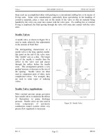
Figure 8 Diesel Engine Valve
piston travels back above the level of
the ports. Valves (refer to figure 8)
are mechanically opened and closed to
admit or exhaust the gasses as needed.
The valves are located in the head
casting of the engine. The point at
which the valve seals against the head
is called the valve seat. Most
medium-sized diesels have either
intake ports or exhaust valves or both
intake and exhaust valves.
Timing Gears, Camshaft, and
Valve Mechanism
In order for a diesel engine to
operate, all of its components must
perform their functions at very precise intervals in relation to the motion of the piston.
To accomplish this, a component called a camshaft is used. Figure 9 illustrates a
camshaft and camshaft drive gear. Figure 2 and Figure 3 illustrate the location of a
camshaft in a large overhead cam diesel engine.
Figure 9 Diesel Engine Camshaft and Drive Gear
A camshaft is a long
bar with egg-shaped
eccentric lobes, one
lobe for each valve and
fuel injector (discussed
later). Each lobe has a
follower as shown on
Figure 10. As the
camshaft is rotated, the
follower is forced up
and down as it follows
the profile of the cam
lobe. The followers are
connected to the
engine's valves and fuel
injectors through
various types of
linkages called pushrods
and rocker arms. The
ME-01 Rev. 0
Page 10
Diesel Engine Fundamentals DOE-HDBK-1018/1-93 DIESEL ENGINES
pushrods and rocker arms transfer the reciprocating motion generated by the camshaft
lobes to the valves and injectors, opening and closing them as needed. The valves are
maintained closed by springs.
As the valve is opened by the camshaft, it compresses the valve spring. The energy
stored in the valve spring is then used to close the valve as the camshaft lobe rotates out
from under the follower. Because an engine experiences fairly large changes in
temperature (e.g., ambient to a normal running temperature of about 190°F), its
components must be designed to allow for thermal expansion. Therefore, the valves,
valve pushrods, and rocker arms must have some method of allowing for the expansion.
This is accomplished by the use of valve lash. Valve lash is the term given to the "slop"
or "give" in the valve train before the cam actually starts to open the valve.
The camshaft is driven by
Figure 10 Diesel Engine Valve Train
the engine's crankshaft
through a series of gears
called idler gears and
timing gears. The gears
allow the rotation of the
camshaft to correspond or
be in time with, the
rotation of the crankshaft
and thereby allows the
valve opening, valve
closing, and injection of
fuel to be timed to occur at
precise intervals in the
piston's travel. To
increase the flexibility in
timing the valve opening,
valve closing, and injection
of fuel, and to increase
power or to reduce cost,
an engine may have one or
more camshafts. Typically,
in a medium to large V-type engine, each bank will have one or more camshafts per head.
In the larger engines, the intake valves, exhaust valves, and fuel injectors may share a
common camshaft or have independent camshafts.
Depending on the type and make of the engine, the location of the camshaft or shafts
varies. The camshaft(s) in an in-line engine is usually found either in the head of the
engine or in the top of the block running down one side of the cylinder bank. Figure 10
provides an example of an engine with the camshaft located on the side of the engine.
Figure 3 provides an example of an overhead cam arrangement as on a V-type engine.
On small or mid-sized V-type engines, the camshaft is usually located in the block at the
Rev. 0 ME-01
Page 11
DIESEL ENGINES DOE-HDBK-1018/1-93 Diesel Engine Fundamentals
center of the "V" between the two banks of cylinders. In larger or multi-camshafted V-
type engines, the camshafts are usually located in the heads.
Blower
The diesel engine's blower is part of the air intake system and serves to compress the
incoming fresh air for delivery to the cylinders for combustion. The location of the
blower is shown on Figure 2. The blower can be part of either a turbocharged or
supercharged air intake system. Additional information on these two types of blowers is
provided later in this module.
Diesel Engine Support Systems
A diesel engine requires five supporting systems in order to operate: cooling, lubrication, fuel
injection, air intake, and exhaust. Depending on the size, power, and application of the diesel,
these systems vary in size and complexity.
Engine Cooling
Figure 11 Diesel Engine Cooling System
Nearly all diesel
engines rely on a
liquid cooling
system to transfer
waste heat out of
the block and
internals as shown
in Figure 11. The
cooling system
consists of a closed
loop similar to that
of a car engine and
contains the
following major
components: water
pump, radiator or
heat exchanger,
water jacket (which
consists of coolant
passages in the
block and heads),
and a thermostat.
ME-01 Rev. 0
Page 12
Diesel Engine Fundamentals DOE-HDBK-1018/1-93 DIESEL ENGINES
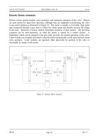
Engine Lubrication
An internal combustion engine would not run for even a few minutes if the moving parts
were allowed to make metal-to-metal contact. The heat generated due to the tremendous
amounts of friction would melt the metals, leading to the destruction of the engine. To
prevent this, all moving parts ride on a thin film of oil that is pumped between all the
moving parts of the engine.
Once between the moving parts, the oil serves two purposes. One purpose is to lubricate
the bearing surfaces. The other purpose is to cool the bearings by absorbing the friction-
generated heat. The flow of oil to the moving parts is accomplished by the engine's
internal lubricating system.
Figure 12 Diesel Engine Internal Lubrication System
Rev. 0 ME-01
Page 13
DIESEL ENGINES DOE-HDBK-1018/1-93 Diesel Engine Fundamentals
Oil is accumulated and stored in the engine's oil pan where one or more oil pumps take
a suction and pump the oil through one or more oil filters as shown in Figure 12. The
filters clean the oil and remove any metal that the oil has picked up due to wear. The
cleaned oil then flows up into the engine's oil galleries. A pressure relief valve(s)
maintains oil pressure in the galleries and returns oil to the oil pan upon high pressure.
The oil galleries distribute the oil to all the bearing surfaces in the engine.
Once the oil has cooled and lubricated the bearing surfaces, it flows out of the bearing
and gravity-flows back into the oil pan. In medium to large diesel engines, the oil is also
cooled before being distributed into the block. This is accomplished by either an internal
or external oil cooler. The lubrication system also supplies oil to the engine's governor,
which is discussed later in this module.
Fuel System
All diesel engines require a method to store and deliver fuel to the engine. Because
diesel engines rely on injectors which are precision components with extremely tight
tolerances and very small injection hole(s), the fuel delivered to the engine must be
extremely clean and free of contaminants.
The fuel system must, therefore,
Figure 13 Diesel Engine Fuel Flowpath
not only deliver the fuel but also
ensure its cleanliness. This is
usually accomplished through a
series of in-line filters.
Commonly, the fuel will be
filtered once outside the engine
and then the fuel will pass through
at least one more filter internal to
the engine, usually located in the
fuel line at each fuel injector.
In a diesel engine, the fuel system
is much more complex than the
fuel system on a simple gasoline
engine because the fuel serves two
purposes. One purpose is
obviously to supply the fuel to run the engine; the other is to act as a coolant to the
injectors. To meet this second purpose, diesel fuel is kept continuously flowing through
the engine's fuel system at a flow rate much higher than required to simply run the
engine, an example of a fuel flowpath is shown in Figure 13. The excess fuel is routed
back to the fuel pump or the fuel storage tank depending on the application.
ME-01 Rev. 0
Page 14
Diesel Engine Fundamentals DOE-HDBK-1018/1-93 DIESEL ENGINES
Air Intake System
Because a diesel engine requires close tolerances to achieve its compression ratio, and
because most diesel engines are either turbocharged or supercharged, the air entering the
engine must be clean, free of debris, and as cool as possible. Turbocharging and
supercharging are discussed in more detail later in this chapter. Also, to improve a
turbocharged or supercharged engine's efficiency, the compressed air must be cooled after
being compressed. The air intake system is designed to perform these tasks.
Air intake systems vary greatly
Figure 14 Oil Bath Air Filter
from vendor to vendor but are
usually one of two types, wet or
dry. In a wet filter intake system,
as shown in Figure 14, the air is
sucked or bubbled through a
housing that holds a bath of oil
such that the dirt in the air is
removed by the oil in the filter.
The air then flows through a
screen-type material to ensure any
entrained oil is removed from the
air. In a dry filter system, paper,
cloth, or a metal screen material is
used to catch and trap dirt before
it enters the engine (similar to the
type used in automobile engines).
In addition to cleaning the air, the
intake system is usually designed
to intake fresh air from as far
away from the engine as
practicable, usually just outside of
the engine's building or enclosure.
This provides the engine with a
supply of air that has not been
heated by the engine's own waste
heat.
The reason for ensuring that an engine's air supply is as cool as possible is that cool air
is more dense than hot air. This means that, per unit volume, cool air has more oxygen
than hot air. Thus, cool air provides more oxygen per cylinder charge than less dense,
hot air. More oxygen means a more efficient fuel burn and more power.
Rev. 0 ME-01
Page 15
DIESEL ENGINES DOE-HDBK-1018/1-93 Diesel Engine Fundamentals
After being filtered, the air is routed by the intake system into the engine's intake
manifold or air box. The manifold or air box is the component that directs the fresh air
to each of the engine's intake valves or ports. If the engine is turbocharged or
supercharged, the fresh air will be compressed with a blower and possibly cooled before
entering the intake manifold or air box. The intake system also serves to reduce the air
flow noise.
Turbocharging
Turbocharging an engine occurs when the engine's own exhaust gasses are forced
through a turbine (impeller), which rotates and is connected to a second impeller
located in the fresh air intake system. The impeller in the fresh air intake system
compresses the fresh air. The compressed air serves two functions. First, it
increases the engine's available power by increasing the maximum amount of air
(oxygen) that is forced into each cylinder. This allows more fuel to be injected
and more power to be produced by the engine. The second function is to increase
intake pressure. This improves the scavenging of the exhaust gasses out of the
cylinder. Turbocharging is commonly found on high power four-stroke engines.
It can also be used on two-stroke engines where the increase in intake pressure
generated by the turbocharger is required to force the fresh air charge into the
cylinder and help force the exhaust gasses out of the cylinder to enable the engine
to run.
Supercharging
Supercharging an engine performs the same function as turbocharging an engine.
The difference is the source of power used to drive the device that compresses the
incoming fresh air. In a supercharged engine, the air is commonly compressed
in a device called a blower. The blower is driven through gears directly from the
engines crankshaft. The most common type of blower uses two rotating rotors
to compress the air. Supercharging is more commonly found on two-stroke
engines where the higher pressures that a supercharger is capable of generating
are needed.
Exhaust System
The exhaust system of a diesel engine performs three functions. First, the exhaust system
routes the spent combustion gasses away from the engine, where they are diluted by the
atmosphere. This keeps the area around the engine habitable. Second, the exhaust system
confines and routes the gasses to the turbocharger, if used. Third, the exhaust system
allows mufflers to be used to reduce the engine noise.
ME-01 Rev. 0
Page 16