báo cáo khoa học: " Three lateral osteotomy designs for bilateral sagittal split osteotomy: biomechanical evaluation with three-dimensional finite element analysis" ppt
Bạn đang xem bản rút gọn của tài liệu. Xem và tải ngay bản đầy đủ của tài liệu tại đây (1.28 MB, 10 trang )
RESEARC H Open Access
Three lateral osteotomy designs for bilateral
sagittal split osteotomy: biomechanical evaluation
with three-dimensional finite element analysis
Hiromasa Takahashi
1*
, Shigeaki Moriyama
2
, Haruhiko Furuta
1
, Hisao Matsunaga
2
, Yuki Sakamoto
2
, Toshihiro Kikuta
1
Abstract
Background: The location of the lateral osteotomy cut during bilateral sagittal split osteotomy (BSSO) varies
according to the surgeon’s preference, and no consensus has been reached regarding the ideal location from the
perspective of biomechanics. The purpose of this study was to evaluate the mechanical behavior of the mandible
and screw-miniplate system among three lateral osteotomy designs for BSSO by using three-dimensional (3-D)
finite element analysis (FEA).
Methods: The Trauner-Obwegeser (TO), Obwegeser (Ob), and Obwegeser-Dal Pont (OD) methods were used for
BSSO. In all the FEA simulations, the distal segments were advanced by 5 mm. Each model was fixed by using
miniplates. These were applied at four different locations, including along Champy’s lines, to give 12 different FEA
miniplate fixation methods. We examined these models under two different lo ads.
Results: The magnitudes of tooth displacement, the maximum bone stress in the vicinity of the screws, and the
maximum stress on the screw-miniplate system were less in the OD method than in the Ob and TO methods at all
the miniplate locations. In addition, Champy’s lines models were less than those at the other miniplate locations.
Conclusions: The OD method allows greater mechanical stability of the mandible than the other two techniques.
Further, miniplates placed along Champy’s lines provide greater mechanical advantage than those placed at other
locations.
Background
Bilateral sagittal split osteotomy (BSSO) is the most
common orthognathic surgical procedure [1]. It was
first described by Trauner and Obwegese r in 1957 [2].
Since then, several modifications of the technique have
been introduced with the aim of improving surgical con-
venience, minimizing morbidity, and maximizing proce-
dural stability. These modifications include the
technique described by Dal Pont [3]; it is generally
recognized that the buccal osteotomy cut of the Obwe-
geser-Dal Pont method is positioned more anteriorly
than that of the Obwegeser method [4], thereby increas-
ing the amount of cancellous bone contact.
There are several factors determining the optimal
modification for BSSO in a patient, including the
position of the m andibular foramen (lingual), course of
the inferior alveolar nerve in the mandible, presence of
the mandibular third molars, and planned direc tion and
magnitude of distal segment movement [5]. However,
the location of the lateral osteotomy cut for BSSO varies
according to the surgeon’s preference, and no consensus
has been reached regarding the ideal location from the
perspective of biomechanics. Although biomechanics is
only one of the factors determining the osteotomy tech-
nique to be used, it is important for the surgeon to con-
sider the presence of jaw deformities while planning the
treatment strategy.
Rigid internal fix ation is routinely used to stabilize the
proximal and distal segments following BSSO, for fast
bone healing, initiating early postoperative mandibular
function, and decreasing the amount of relapse [6].
Similarly, a stable osteotomy design is desired. Although
numerous studies have been conducted to compa re the
different types of fixation techniques, experiments
* Correspondence:
1
Department of Oral and Maxillofacial Surgery, Faculty of Medicine, Fukuoka
University, 7-45-1 Nanakuma, Jonan-ku, Fukuoka, Japan
Takahashi et al. Head & Face Medicine 2010, 6:4
/>HEAD & FACE MEDICINE
© 2010 Takahas hi et al; licensee BioMed Central Ltd. This is an Open Access article distributed under the terms of the Creative
Commons Attribution License (http://creativecommon s.org/licenses/by/2 .0), which permits unrestricted use, distribut ion, and
reprodu ction in any medium, provided the original work is properly cited.
compa ring different BSSO techniques for use in orthog-
nathic surgery are limited [7].
Korkmaz et al. [8] have fou nd that the miniplate
orientation and shape are not the primary factors aff ect-
ing the stability; the location of the miniplates (superior,
middle, or inferior) was determined to be the main
parameter by using finite element analysis (FEA) simula-
tion. Champy et al. [9] determined “the ideal line of
osteosynthesis in the mandible,” where miniplate fixa-
tion is the most stable. Therefore, when comparing the
stability of BSS O techniques, not only the location for
the osteotomy cut but also the location of the miniplate
may influence mandibular stability. Therefore, to com-
pare the stability of different lateral osteotomy methods
absolutely, we should eliminate the possibility that the
location of the miniplates will affect the stability.
FEA is widely used in engineering and can also be
used to solve complex problems in dentistry [10]. Sev-
eral authors have reported the accuracy of FEA for
describing the biomechanical behavior of bony speci-
mens [11-13]. We had earlier reported the feasibility of
FEA simulation to compare experimental studies and
FEA simulations [14]. Vollmer et al. [15] have found
quite a high correlation between FEA simulation and in
vitro measurements of mandibular specimens (correla-
tion coefficient = 0.992). FEA is therefore a suitable
numerical method for addressing biomechanical ques-
tions and a powerful research tool that can provide pre-
cise insight into the complex mechanical behavior of the
mandible affected by mechanical loading, which is diffi-
cult to assess by other means [16-18].
In this study, we aimed to assess three lateral osteot-
omy designs (i.e., cuts at the ramus, mandibular angle,
and mandibular body regions) from the viewpoint of
biomechanical stability and the complex biomechanical
behavior of the mandible and screw-miniplate system.
For this, we used FEA simulations of three BSSO techni-
ques with miniplate fixation at four different locations,
resulting in 12 FEA miniplate fixation methods. We
then applied inci sal and contralateral molar compressive
loads to compare the resultant incisal and bilateral
molar displacements as well as the maximum von Mises
stress in the screw-miniplate system and maximum
bone stress in the vicinity of the screws among the
miniplate fixation methods. Here, we show that the
Obwegeser-Dal Pont meth od for BSSO allows the great-
est mechanical stability of the mandible.
Methods
Mandibular modeling
We performed a computed tomography (CT) scan
(Aquillion 64 DAS TSX-1014/H A; Toshiba Medical Sys-
tems, Tokyo, Jap an) of a synthetic mandible model
(8596; Synbone AG, Malans, Switzerland) made of
polyurethane. The polyurethane replica was created
from exactly matched human anatom y in all dimensions
and proportions [19]. A three-dimensional (3-D) FEA
model was constructed from 0.5-mm serial axial sec-
tions apart from the two-dimensional (2-D) CT image.
The model consisted of 134,836 elements and 29,582
nodes. For simplification, bone was assumed to be a sin-
gle homogenous phase. The material properties were
defined as Young’s modulus of 13.7 GPa and Poisson’s
ratio of 0.3 [20]. We then simulated osteotomy on the
model by using each of three BSSO techniques. The dis-
tal segments were advanced by 5 mm parallel to the
occlusal plane without allowing change in the condylar
position and thenfixed with bilateral monocortical mini-
plate fixation using four screws per miniplate. We
assumed that all the models had perf ect slippage at the
bone interfaces. All surgical simulations and analyses
were performed with Mechanical Finder version 6.0
(Research Center Computational Mechanics, Tokyo,
Japan).
The BSSO techniques
Mandibular biomechanical stability was compared
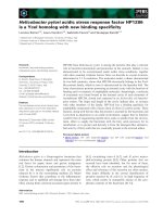
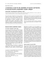
among three BSSO techniques (Fig. 1). In the T rauner-
Obwegeser (TO) method, the lateral osteotomy cut was
made horizontally from the distal region of the second
molar to the posterior border well above the mandibular
angle. This osteotomy technique was first performed in
1955 [21] and published in English in 1957 [2].
Figure 1 Schematic of the three lateral osteotomy des igns for
bilateral sagittal split osteotomy (BSSO). (A) In the Trauner-
Obwegeser (TO) method, the lateral osteotomy cut was made
horizontally from the distal region of the second molar to the
posterior border well above the mandibular angle. (B) In the
Obwegeser (Ob) method, the lateral osteotomy cut was made from
the distal region of the second molar to the midpoint of the
mandibular angle. (C) In the Obwegeser-Dal Pont (OD) method, the
lateral osteotomy cut was made vertically from the distal of second
molar to the lower border of the ascending ramus.
Takahashi et al. Head & Face Medicine 2010, 6:4
/>Page 2 of 10
In the Obwegeser (Ob) method, which was introduced
in 1957 [21], the lateral osteotomy cut w as made from
the distal region of the second molar to the midpoint of
the mandibular angle.
In the Obwegeser-Dal Pont (OD) method, the lateral
osteotomy cut was made vertically from the distal of
secondmolartothelowerborderoftheascending
ramus. This osteotomy technique was first performed in
1958 [21] and published in English in 1961 [3].
Miniplate and screw modeling
Each model was stabilized following the simulated
osteotomy by using miniplates and screws. The mini-
plates were not bent and fit the bone surfa ce as closely
as possible. They were simulated as four-hole, straight
titanium miniplates (447-224; Synthes Maxillofacial,
West Chester, PA) of 1.0-mm thickness by using the
3-D computer-aided design software SolidWorks2008
(SolidWorks Japan, Tokyo, Japan). The screws were
simulated as simple 2.0-mm cylinders of length appro-
priate for monocortical penetration and miniplate fixa-
tion. We assumed perfect adaptation between the plate
hole and screw through which it was mounted as well
as between the screws and bone with no slippage at
their interface [8]. The titanium plates and screws were
modeled with Young’ s modulus of 110 GPa and Pois-
son’s ratio of 0.34, using previously reported data [22].
The material properties were the averages of the values
in the literature [23,24].
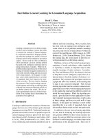
Miniplate locations
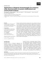
The three BSSO techniques were divided into four sub-
groups each. We compared mandibular biomechanical
stability among four miniplate locations (Fig. 2), which
are frequently encountered inadvertently in the clinical
setting. Therefore, 12 different FEA miniplate fixation
methods were developed (Fig. 3), as follows:
1. A miniplate was applied along Champy’slinesof
ideal osteosynthesis, as close to the alveolar border as
possible (OD-1, Ob-1, and TO-1 methods).
2. A miniplate was placed in translation 5 mm inferior
to the first location (OD-2, Ob-2, and TO-2 methods).
3. A miniplate was placed 20° in clockwise rotation to
the first location (OD-3, Ob-3, and TO-3 methods).
4. A miniplate was placed 20° in counterclockwise
rotation to the first location (OD-4, Ob-4, and TO-4
methods).
Constraints
The bilateral temporomandibular joints were completely
constrained (Fig. 4A).
Loading
We examined these models under two different loads.
For incisal loading, a 66.7-N compressive load was
applied to the central incisors perpendicular to the
occlusal plane (Fig. 4B). For contralateral molar loading,
a 260.8-N compressive load was applied to the occlusal
surface of the right first molar perpendicular to the
occlusal plane (Fig. 4C).
The evaluated parameters
For assessing the stability in the three BSSO techniques,
central incisor displacement on incisal and contralateral
molar loadings, the maximum von Mises stress in the
screw-miniplate system, and the maximum bone stress
in the vicinity of the screws on both loadings were
examined and compared.
For assessing the complex biomechanical behavior on
incisal and contralateral molar loadings, first molar dis-
placement bilaterally, the maximum von Mises stress in
the bilateral screw-miniplate system, and the maximum
bone stress in the vicinity of the bilateral screws in the
OD-1, Ob-1, and TO-1 methods were examined.
Figure 2 Minip late locations . The baseline location was along Champy’s lines; the miniplate was applied along Champy’s lines of ideal
osteosynthesis as close to the alveolar border as possible (the upper miniplates). (A) The miniplate was placed in translation 5 mm inferior to
the baseline location. (B) The miniplate was placed 20° in clockwise rotation to the baseline location. (C) The miniplate was placed 20° in
counterclockwise rotation to the baseline location.
Takahashi et al. Head & Face Medicine 2010, 6:4
/>Page 3 of 10
Namely, we compared the working side and balancing
side on contralateral molar loading.
Results
Central incisor displacement, maximum bone stress,
and maximum von Mises stress
Comparisons of the predicted central incisor displace-
ments, maximum predicted bone mecha nical stress in
the vicinity of the screws, and maximum predicted von
Misesstressinthescrew-miniplate system on incisal
loading and contralateral molar loading are shown in
Table 1 and Table 2, respectively. On comparing the
three BSSO techniques, the OD method showed the
least central incisor displacement, least maximum bone
mechanical stress in the screw vicinity, and least von
Mises stress in the screw-miniplate system on both
loadings, followed by the Ob method and TO method.
Similarly, on comparing the four miniplate locations, the
Champy’s lines models (OD-1, Ob-1, and TO-1 meth-
ods) showed the least tooth displacement, least maxi-
mum bone stress in the screw vicinity, and least
maximum von Mises stress in the screw-miniplate sys-
tem on both loadings, again followed by the Ob method
and TO method.
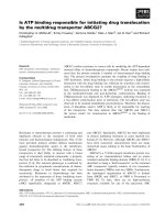
Figure 3 The 12 finite element analysis (FEA) miniplate fixation models.TO-1to4,theTrauner-Obwegesermethod;Ob-1to4,the
Obwegeser method; OD-1 to 4, the Obwegeser-Dal Pont method. The miniplates were fixed as described in Figure 2.
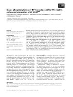
Figure 4 Establishing the constraints and loading.(A)The
bilateral temporomandibular joints were completely constrained. (B)
For incisal loading, a 66.7-N compressive load was applied to the
central incisors perpendicular to the occlusal plane. (C) For
contralateral molar loading, a 260.8-N compressive load was applied
to the occlusal surface of the right first molar perpendicular to the
occlusal plane.
Takahashi et al. Head & Face Medicine 2010, 6:4
/>Page 4 of 10
Detailed analyses of the Champy’s lines model in each
BSSO technique
The displacement fields in the mandibles of the Champy’s
lines models on incisal and contralateral molar loadings
are presented in Figure 5. Comparisons of the predicted
bilateral first molar displacements, maximum bone
mechanical stress in the vicinity of the bilateral screws,
and von Mises stress in th e bilateral screw-miniplate sys-
tems on incisal loading and contralateral molar loading
are shown in Table 3 and Table 4, respectively. Regional
distributions of von Mises bone stress in the vicinity of the
screws and von Mises stress in the bilateral screw-mini-
plate system of the Champy’s lines models on both load-
ings are shown in Figure 6 and Figure 7, respectively.
On incisal loading, for a structurally symmetrical
mandible, the bilateral first molar displacements, maxi-
mum bone stress, and maximum stress on the screw-
miniplate system were nearly symmetrical. I n contrast,
on contralateral molar loading, the right first molar dis-
placements, maximum bone stress, and maximum stress
on the screw-miniplate system were higher than those
of the left side.
The screw site s were numbered in all the models as
1-4 from distal (i.e., the ramus) to proximal (i.e., the
symphysis) [25]. The highest concentration of bone
mechanical stress was found at site 3 bilaterally. Simi-
larly, the site 3 screw and miniplate demonstrated very
high tensile stresses.
Table 1 Summary of the comparative results for incisal loading
Parameter Model TO method Ob method OD method
Deflection at the central incisor (mm) 1 5.323 4.180 3.038
2 5.635 4.550 3.286
3 6.780 4.235 3.222
4 6.989 4.661 3.539
Maximum von Mises bone stress in the screw vicinity (MPa) 1 249.981 190.631 110.492
2 269.497 219.385 132.409
3 289.571 191.092 131.958
4 289.737 253.757 139.572
Maximum von Mises stress on the miniplate (MPa) 1 1459.151 1421.798 1124.772
2 1492.856 1450.541 1247.729
3 1763.471 1443.686 1216.838
4 1939.372 1559.816 1289.623
Maximum von Mises stress on the screws (MPa) 1 904.507 827.426 809.941
2 921.232 919.923 858.749
3 926.003 854.493 829.947
4 964.445 983.235 914.539
Table 2 Summary of the comparative results for contralateral molar loading
Parameter Model TO method Ob method OD method
Deflection at the central incisor (mm) 1 11.357 8.522 4.255
2 14.222 9.665 4.877
3 15.114 8.630 4.786
4 15.271 9.931 4.972
Maximum von Mises bone stress in the screw vicinity (MPa) 1 512.634 361.865 256.623
2 726.506 463.139 325.129
3 730.439 405.240 320.893
4 775.176 504.709 356.547
Maximum von Mises stress on the miniplate (MPa) 1 3250.620 2955.626 1766.932
2 3549.566 3195.330 2082.756
3 3878.755 3127.397 1941.177
4 4261.597 3381.705 2156.119
Maximum von Mises stress on the screws (MPa) 1 2118.952 1778.286 1591.128
2 2239.526 2047.883 1639.485
3 2336.934 1826.871 1609.271
4 2397.104 2476.061 1754.459
Takahashi et al. Head & Face Medicine 2010, 6:4
/>Page 5 of 10
Figure 5 The displacement fields in the mandibles in the OD-1, Ob-1, and TO-1 methods. The displacement fields in the mandibles of the
Champy’s lines models were determined following (A) incisal loading and (B) contralateral molar loading.
Table 3 Incisal loading
Parameter Side TO-1 method Ob-1 method OD-1 method
Deflection at the first molar (mm) Right 2.786 (100%) 2.068 (100%) 1.231 (100%)
Left 2.778 (99.7%) 2.053 (99.2%) 1.205 (97.9%)
Maximum von Mises bone stress in the screw vicinity (MPa) Right 249.981 (100%) 190.631 (100%) 110.492 (100%)
Left 248.304 (99.3%) 189.818 (99.6%) 101.587 (91.9%)
Maximum von Mises stress on the miniplate (MPa) Right 1459.191 (100%) 1421.798 (100%) 1124.772 (100%)
Left 1427.779 (97.8%) 1419.124 (99.8%) 1113.104 (99.0%)
Maximum von Mises stress on the screw (MPa) Right 904.507 (100%) 827.426 (100%) 809.941 (100%)
Left 905.978 (100.2%) 823.438 (99.5%) 797.614 (98.5%)
Table 4 Contralateral molar loading
Parameter Side TO-1 method Ob-1 method OD-1 method
Deflection at the first molar (mm) Right 6.149 (100%) 4.537 (100%) 1.979 (100%)
Left 5.840 (95.0%) 4.161 (91.7%) 1.708 (86.3%)
Maximum von Mises bone stress in the screw vicinity (MPa) Right 512.643 (100%) 361.865 (100%) 256.623 (100%)
Left 441.897 (86.2%) 294.699 (81.4%) 196.790 (76.7%)
Maximum von Mises stress on the miniplate (MPa) Right 3250.620 (100%) 2955.626 (100%) 1766.932 (100%)
Left 3101.392 (95.4%) 2598.595 (87.9%) 1665.914 (94.3%)
Maximum von Mises stress on the screw (MPa) Right 2118.952 (100%) 1778.286 (100%) 1591.128 (100%)
Left 1964.085 (92.7%) 1663.766 (93.6%) 1474.351 (92.7%)
Takahashi et al. Head & Face Medicine 2010, 6:4
/>Page 6 of 10
Discussion
Using FEA simulation, we have s hown that the magni-
tudes of t ooth displacement, the maximum bone stress,
and the maximum stress on the screw-miniplate system
in the OD method were less than those in the Ob and
TO methods at all the miniplate locations on both inci-
sal and contralateral molar loadings. This means that
the OD method provided greater resistance to the simu-
lated functional forces than the other two techniques.
These results only refer to the miniplate fixation techni-
que and not to screws or semirigid systems.
The smaller size of the lever arm in the OD method
probably plays an important role in yielding less stress
and smaller displacement. By using FEA simulation,
Puricelli et al. [7] suggested that their osteotomy techni-
que presents better mechanical stability than the original
OD method. The Puricelli osteotomy is performed at a
region further distal to the osteotomy in the OD
method, performed nearer to the mental foramen. They
speculated that the size of the lever arm decreases as a
result of the increased surface area of medullary bone
contact [26]; we agree with this interpretation of the
results. Howeve r, in our FEA simulation, we did not
consider bone contact (i.e., all the model s were assumed
to have perfect slippage at the bone interfaces), because
osseous healing starts and is not completed in the early
postoperative period. As a matter of course, a larger
surface of bone cont act promotes faster healing and has
less displacement due to muscle activity.
Further, the magnitudes of tooth displacement, the
maximum bone stress, and the maximum stress on the
plating system were less in the Champy’s lines models
than in the other models in our s tudy. This means that
the Champy’s lines models provided greater resistance
to the simulated functional forces than the models with
other miniplate locations.
Champy and colleagues determined “the ideal line of
osteosynthesis ” in the mandible, where miniplate fixa-
tion is the m ost stable [27]. In the mandibular angle
region, this line indicates that a plate may be placed
either along or just below the oblique line of the mand-
ible [9]. Similarly, in our FEA simulation, the models
with miniplates placed along Champy’ slinesdemon-
strated a trend toward higher stability than those with
other miniplate locations. Unfortunately, the ideal sites
frequently overlap tooth roots. Avoidance of damage to
the roots of teeth and contents of the inferior alveolar
canal is important [27].
In an in vitro study, Ozden et al. [28] compared the
biomechanical stability of ten different fixation methods
used in BSSO by using fresh sheep mandibles. Their
osteotomy line was similar to that used in our OD
method. They tentatively claimed that a miniplate
placed obliquely in a clockwise pattern provides greater
Figure 6 Regional distributions of von Mises bone stress in the vicinity of the screws in the OD-1, Ob-1, and TO-1 methods.The
highest concentration of bone mechanical stress was found at site 3 bilaterally in all three methods on (A) incisal loading and (B) contralateral
molar loading.
Takahashi et al. Head & Face Medicine 2010, 6:4
/>Page 7 of 10
stability than that placed horizontally. In contrast, in our
FEA simulation, the miniplate placed horizontally (OD-1
method) provided greater biomechanical stability than
that placed obliquely in a clockwise pattern (OD-3
method). Similarly, in the other BSSO techniques, the
rotated miniplate model provided less stability than the
Champy’ s lines models. Therefore, the relationship
between angular variation of a miniplate and orientation
of the loading may contribute to mechanical stability.
However, this relat ionship has not been systematically
studied and warrants further investigation.
Dal Pont et al. [3] demonstrated that the advantages
of the OD method are better and easier adaptation of
the fragments; broader contact surfaces; greater possibi-
lity for correction of prognathism, micrognathia, and
apertognathia; and avoidance of as much muscular dis-
placement as possible. On the basis of our findings, we
can append another advantage: the OD method provides
greater resistance to functional forces than the other
BSSO techniques. Good stability of the mandible in the
early postoperative period may contribute to primary
bone union, immediate postoperative function, and a
shortened maxill omandibular fixation period. Moreover,
Dolce et al. [29] reported that most of the relapse
occurs within the first 8 weeks postsurgically, consistent
with the findings of other authors.
Furthermore, when we observed the Champy’slines
models closely, the tooth displacements and stresses on
the mandible bilaterally were in the same range on inci-
sal loading. In contrast, on contralateral molar loading,
the displacements and stresses on the working side were
great er that those on the balancing side. The magnitude
of all the parameters on the balancing side accounted
for about 80% of that on the working side, which is
higher than we had thought. Korioth and Hannam [30]
have indicated that under conditions of static equili-
brium and within the l imitations of the current model-
ing approach, the human jaw deforms elastically during
symmetrical and asymmetrical clenching tasks. This
deformation is complex, and includes the rotational dis-
tortion of the corpora around their axes. In addition,
the jaw deforms parasagittally and transversely.
Figure 7 Regional distributions of von Mises stress on the bilateral screw-miniplate systems in the OD-1, Ob-1, and TO-1 methods.
The site 3 screws and miniplates demonstrated very high tensile stresses in all three methods on (A) incisal loading and (B) contralateral molar
loading.
Takahashi et al. Head & Face Medicine 2010, 6:4
/>Page 8 of 10
A wide range of magnitudes of chew ing forces after
BSSO has been reported [31-33]. We assumed the early
postoperative condition in this FEA simulation. Mastica-
tory loads of 66.7 N on the central incisors and 260.8 N
on the right first molar were simulat ed, corresponding to
the mean immediate postoperative (mandibular advance-
ment) bite force [33]. Although such bite forces were not
measured experimentally, it i s possible to estimate them
by multiplying the rates of improvement [33].
We evaluated the biomechanical behavior in the three
BSSO techniques following fixation using miniplates and
screws. Although the applied incisal loading mimicked
vertically deforming forces and molar loading mimicked
torsionally deforming forces encountered under clinical
circumstances, they cannot completely represent the
complex interaction between the mandible and muscula-
ture in function. Therefore, we can only expect to iden-
tify trends in behavior that will help in making decisions
clinically [34].
In our study, the highest concentration of bone
mechanical stress was found at site 3 in a ll the Cham-
py’s lines models. Similarly, the highest concentration of
mechanical stress was found on the site 3 screws and
upper outer rim of the miniplate near site 3. Chuong et
al. [25] produced a 3-D finite element model and exam-
ined the stress on fixation after BSSO. They reported
that the stress was concentrated on the upper outside
rim of the miniplate near site 3, as seen in our results.
It has been suggested that this stress concentration is
responsible for the screw loosening and miniplate break-
age seen clinically [35,36].
Armstrong et al. [37] reported the limitations of in
vitro experimental study for comparing the multitude of
rigid fixation systems. These limitations are almost the
same as those of FEA simulation and include the follow-
ing: the fixation systems were tested by using forces
applied vertically, whereas mixed vertical, l ateral, and
rotational forces may be encountered clinically as dic-
tated by the anatomical environment; the in situ plates
may be affected by the physiological environment (e.g.,
inflammation or infection); and the plates were sub-
jected to a single continuous load and not repeatedly
loaded as in normal function. In addition to these lim-
itations, FEA simulation also has some inherent limita-
tions [10,16]. The values of the stresses provided by
FEA are not necessarily identical to the real ones. In
this study, we made several assumptions and simplifi ca-
tions regarding the material properties and model gen-
eration. In FEA models, bone is frequently modeled as
isotropic, but it is actually anisotropic. In this study,
bone was modeled as homogeneous, isotropic, and line-
arly elastic. Another crucial limitation is that the mini-
plates were not bent, whereas the plates are often
adapted to fit the contour of the bone surface clinically.
Nonetheless, the FEA simulation allowed realistic repre-
sentation of the stress distribution in the fixation
material.
Conclusions
The OD method allows greater mechanical stability of
the mandible than the other two BSSO techniques. In
addition, miniplates placed along Champy’s lines provide
greater mechanical advantage than those placed at other
locations.
Acknowledgements
We thank Associate Prof. Kazuhiko Okamura, Department of Morphol ogical
Biology at Fukuoka Dental College, Japan, for his thoughtful review of this
manuscript. This work was supported in part by a fund (096006) from the
Central Research Institute of Fukuoka University, Japan.
Author details
1
Department of Oral and Maxillofacial Surgery, Faculty of Medicine, Fukuoka
University, 7-45-1 Nanakuma, Jonan-ku, Fukuoka, Japan.
2
Department of
Mechanical Engineering, Faculty of Engineering, Fukuoka University, 8-19-1
Nanakuma, Jonan-ku, Fukuoka, Japan.
Authors’ contributions
HF conceived the study design. HT conceptualized the study design, wrote
the manuscript, and participated in the FEA analyses. SM, YS, and HM
participated in the FEA analyses. TK edited and reviewed the manuscript. All
authors read and approved the final manuscript.
Competing interests
The authors declare that they have no competing interests.
Received: 16 July 2009 Accepted: 26 March 2010
Published: 26 March 2010
References
1. Watzke IM, Turvey TA, Phillips C, Proffit WR: Stability of mandibular
advancement after sagittal osteotomy with screw or wire fixation: a
comparative study. J Oral Maxillofac Surg 1990, 48:108-121, discussion
122-123.
2. Trauner R, Obwegeser H: The surgical correction of mandibular
prognathism and retrognathia with consideration of genioplasty. I.
Surgical procedures to correct mandibular prognathism and reshaping
of the chin. Oral Surg Oral Med Oral Pathol 1957, 10:677-689, contd.
3. Dal Pont G: Retromolar osteotomy for the correction of prognathism.
J Oral Surg Anesth Hosp Dent Serv 1961, 19:42-47.
4. Hashiba Y, Ueki K, Marukawa K, Shimada M, Yoshida K, Shimizu C, Alam S,
Nakagawa K: A comparison of lower lip hypoesthesia measured by
trigeminal somatosensory-evoked potential between different types of
mandibular osteotomies and fixation. Oral Surg Oral Med Oral Pathol Oral
Radiol Endod 2007, 104:177-185.
5. Cillo JE, Stella JP: Selection of sagittal split ramus osteotomy technique
based on skeletal anatomy and planned distal segment movement:
current therapy. J Oral Maxillofac Surg 2005, 63:109-114.
6. Chung IH, Yoo CK, Lee EK, Ihm JA, Park CJ, Lim JS, Hwang KG:
Postoperative stability after sagittal split ramus osteotomies for a
mandibular setback with monocortical plate fixation or bicortical screw
fixation. J Oral Maxillofac Surg 2008, 66:446-452.
7. Puricelli E, Fonseca JS, de Paris MF, Sant’Anna H: Applied mechanics of the
Puricelli osteotomy: a linear elastic analysis with the finite element
method. Head Face Med 2007, 3:38.
8. Korkmaz HH: Evaluation of different miniplates in fixation of fractured
human mandible with the finite element method. Oral Surg Oral Med
Oral Pathol Oral Radiol Endod 2007, 103:e1-13.
9. Champy M, Loddé JP, Schmitt R, Jaeger JH, Muster D: Mandibular
osteosynthesis by miniature screwed plates via a buccal approach.
J Maxillofac Surg 1978, 6:14-21.
Takahashi et al. Head & Face Medicine 2010, 6:4
/>Page 9 of 10
10. Erkmen E, Simsek B, Yücel E, Kurt A: Three-dimensional finite element
analysis used to compare methods of fixation after sagittal split ramus
osteotomy: setback surgery-posterior loading. Br J Oral Maxillofac Surg
2005, 43:97-104.
11. Voo K, Kumaresan S, Pintar FA, Yoganandan N, Sances A Jr: Finite-element
models of the human head. Med Biol Eng Comput 1996, 34:375-381.
12. Hart RT, Hennebel VV, Thongpreda N, Van Buskirk WC, Anderson RC:
Modeling the biomechanics of the mandible: a three-dimensional finite
element study. J Biomech 1992, 25:261-286.
13. Korioth TW, Versluis A: Modeling the mechanical behavior of the jaws
and their related structures by finite element (FE) analysis. Crit Rev Oral
Biol Med 1997, 8:90-104.
14. Takahashi H, Furuta H, Moriyama S, Sakamoto Y, Matsunaga H, Kikuta T:
Assessment of three bilateral sagittal split osteotomy techniques with
respect to mandibular biomechanical stability by experimental study
and finite element analysis simulation. Med Bull Fukuoka Univ .
15. Vollmer D, Meyer U, Joos U, Vègh A, Piffko J: Experimental and finite
element study of a human mandible. J Craniomaxillofac Surg 2000,
28:91-96.
16. Erkmen E, Atac MS, Yücel E, Kurt A: Comparison of biomechanical
behaviour of maxilla following Le Fort I osteotomy with 2- versus
4-plate fixation using 3D-FEA: part 3: inferior and anterior repositioning
surgery. Int J Oral Maxillofac Surg 2009, 38:173-179.
17. Simsek B, Erkmen E, Yilmaz D, Eser A: Effects of different inter-implant
distances on the stress distribution around endosseous implants in
posterior mandible: a 3D finite element analysis. Med Eng Phys 2006,
28:199-213.
18. Yoon HJ, Rebellato J, Keller EE: Stability of the Le Fort I osteotomy with
anterior internal fixation alone: a case series. J Oral Maxillofac Surg 2005,
63:629-634.
19. Haug RH, Fattahi TT, Goltz M: A biomechanical evaluation of mandibular
angle fracture plating techniques. J Oral Maxillofac Surg 2001,
59:1199-1210.
20. Tanne K, Miyasaka J, Yamagata Y, Sachdeva R, Tsutsumi S, Sakuda M: Three-
dimensional model of the human craniofacial skeleton: method and
preliminary results using finite element analysis. J Biomed Eng 1988,
10:246-252.
21. Obwegeser HL: Orthognathic surgery and a tale of how three
procedures came to be: a letter to the next generations of surgeons.
Clin Plast Surg 2007, 34:331-355.
22. Arbag H, Korkmaz HH, Ozturk K, Uyar Y: Comparative evaluation of
different miniplates for internal fixation of mandible fractures using
finite element analysis. J Oral Maxillofac Surg 2008, 66:1225-1232.
23. Geng JP, Tan KB, Liu GR: Application of finite element analysis in implant
dentistry: a review of the literature. J Prosthet Dent 2001, 85:585-598.
24. Fernández JR, Gallas M, Burguera M, Viaño JM: A three-dimensional
numerical simulation of mandible fracture reduction with screwed
miniplates. J Biomech 2003, 36
:329-337.
25. Chuong CJ, Borotikar B, Schwartz-Dabney C, Sinn DP: Mechanical
characteristics of the mandible after bilateral sagittal split ramus
osteotomy: comparing 2 different fixation techniques. J Oral Maxillofac
Surg 2005, 63:68-76.
26. Puricelli E: A new technique for mandibular osteotomy. Head Face Med
2007, 3:15.
27. Worthington P, Champy M: Monocortical miniplate osteosynthesis.
Otolaryngol Clin North Am 1987, 20:607-620.
28. Ozden B, Alkan A, Arici S, Erdem E: In vitro comparison of biomechanical
characteristics of sagittal split osteotomy fixation techniques. Int J Oral
Maxillofac Surg 2006, 35:837-841.
29. Dolce C, Van Sickels JE, Bays RA, Rugh JD: Skeletal stability after
mandibular advancement with rigid versus wire fixation. J Oral Maxillofac
Surg 2000, 58:1219-1227, discussion 1227-1228.
30. Korioth TW, Hannam AG: Deformation of the human mandible during
simulated tooth clenching. J Dent Res 1994, 73:56-66.
31. Kikuta T, Hara I, Seto T, Yoshioka I, Nakashima T, Yasumitsu C: Evaluation of
masticatory function after sagittal split ramus osteotomy for patients
with mandibular prognathism. Int J Adult Orthodon Orthognath Surg 1994,
9:9-17.
32. Harada K, Watanabe M, Ohkura K, Enomoto S: Measure of bite force and
occlusal contact area before and after bilateral sagittal split ramus
osteotomy of the mandible using a new pressure-sensitive device:
a preliminary report. J Oral Maxillofac Surg 2000, 58:370-373, discussion
373-374.
33. Throckmorton GS, Buschang PH, Ellis E: Improvement of maximum
occlusal forces after orthognathic surgery. J Oral Maxillofac Surg 1996,
54:1080-1086.
34. Peterson GP, Haug RH, Van Sickels J: A biomechanical evaluation of
bilateral sagittal ramus osteotomy fixation techniques. J Oral Maxillofac
Surg 2005, 63:1317-1324.
35. Nakajima M, Motohashi T, Okuda K, Sunada N, Shojyu Y, Yoshimoto H,
Tanaka K, Kakudo K, Matsumoto N, Matsumoto T: Biomechanical analysis
by the three-dimensional finite element method of stress in bone
fixation plates after sagittal spliting ramus osteotomy. J Osaka Dent Univ
2007, 41:89-96.
36. Fujioka M, Fujii T, Hirano A: Complete breakage of three-dimensional
miniplates: unusual complication of osteosynthesis after sagittal split
osteotomy. Two case reports. Scand J Plast Reconstr Surg Hand Surg 2000,
34:259-263.
37. Armstrong JE, Lapointe HJ, Hogg NJ, Kwok AD: Preliminary investigation
of the biomechanics of internal fixation of sagittal split osteotomies
with miniplates using a newly designed in vitro testing model. J Oral
Maxillofac Surg 2001, 59:191-195.
doi:10.1186/1746-160X-6-4
Cite this article as: Takahashi et al.: Three lateral osteotomy designs for
bilateral sagittal split osteotomy: biomechanical evaluation with three-
dimensional finite element analysis. Head & Face Medicine 2010 6:4.
Submit your next manuscript to BioMed Central
and take full advantage of:
• Convenient online submission
• Thorough peer review
• No space constraints or color figure charges
• Immediate publication on acceptance
• Inclusion in PubMed, CAS, Scopus and Google Scholar
• Research which is freely available for redistribution
Submit your manuscript at
www.biomedcentral.com/submit
Takahashi et al. Head & Face Medicine 2010, 6:4
/>Page 10 of 10