Thumb for Mechanical Engineers 2011 Part 4 doc
Bạn đang xem bản rút gọn của tài liệu. Xem và tải ngay bản đầy đủ của tài liệu tại đây (1.36 MB, 30 trang )
80
Rules
of
Thumb
for
Mechanical Engineers
Equipment Checks
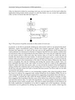
One of the most important considerations for reliable seal
performance
is
the operating condition of the equipment.
Many times, mechanical seal failures are a direct result of
poor equipment maintenance. High vibration, misalign-
ment, pipe strain, and many other detrimental conditions
cause poor mechanical seal life. There are also several di-
mensional checks that are often overlooked.
Because half of the seal is rotating with the
shaft,
and the
other half is fixed to a stationary housing, the dimension-
al relationships of concentricity and “squareness”
are
very
important. The centrifugal pump
is
by far the most common
piece of rotating equipment utilizing a mechanical seal.
For
this reason, the dimensional checks
will
be referenced
to
the shaft and seal chamber for a centrifugal pump.
Axial Shaft Movement
Axial shaft movement (Figure
28)
can be measured by
placing a dial indicator at the end
of
the shaft and gently tap-
ping
or
pulling the shaft back and forth. The indicator
movement should be no more
than
0.010’’
TIR
[
11.
Radial
Bearing
U
Figure
28.
Checking pump
for
axial shaft movement.
(Courtesy
of
Durametallic Cop.)
~~
Radial Shaft Movement
There are two types of radial shaft movement (Figure
Mid
Bearing
29)
that need to be inspected. The first type is called
shafi
defection,
and is a good indication of bearing con-
ditions and bearing housing fits. To measure, install the
dial
indicators as shown, and lift up
or
push down
on
the
end
of
the shaft. The indicator movement should not
ex-
ceed
0.002”
TIR
[
11.
The second type of radial shaft movement
is
called
shu#
mn-out,
and
is
a good way to check for a bent shaft con-
dition.
To
measure, install the dial indicators as shown in
Figure
29.
Checking pump
for
radial shaft movement.
(Coudesy
of
Durametallic Cop.)
Mechanical
Seals
81
Seal Chamber Face Run-Out
Figure
29,
and slowly
turn
the shaft. The indicator move-
ment should not exceed
0.003”
TIR
[
11.
As stated
earlier,
because the stationary portion of the me-
chanical
seal
bolts directly to the pump case, it is very im-
portant that the face of the seal chamber be perpendicular
to the
shaft
center-line. To check for “out-of-squareness,”
mount the dial indicator directly to the shaft, as shown in
Figure
30.
Sweep the indicator around the face of the seal
housing by slowly turning the shaft. The indicator move-
ment should not exceed
0.005”
TIR
[
11.
Radial
Bearing
Eearlng-r
Figure
30.
Checking pump
for
seal chamber face
out.
(CouWy of Durametallic Corp.)
run-
Seal Chamber Bore Concentricity
There
are
several stationary seal components that have
close diametrical clearances to the shaft, such as the throt-
tle bushing. For
this
reason, it is important for the seal
chamber to be concentric with the pump shaft. Addition-
ally, for gland ring designs with
O.D.
pilots, the outer reg-
ister must also
be
concentric.
To
measure, install the dial
indicators as shown in Figure
3
1. The indicator movement
should not exceed
0.005”
TIR
[
11.
Figure
31.
Checking pump
for
seal chamber bore con-
centricity.
(Courtesy
of
Durametallic Corp.)
CALCULATING SEAL CHAMBER PRESSURE
The
seal
chamber pressure is a very important
data
point
for selecting both the proper seal design and
seal
flush
scheme. Udortumtely, the
seal
chamber
pressure
varies con-
siderably with different pump designs and impeller styles.
Some pumps operate with chamber pressures close
to
suc-
tion pressure, while others are near discharge pressure.
The easiest and most accurate way to determine the seal
chamber pressure
on
an existing pump
is
simply to mea-
sure
it. Install a pressure gauge into a tapped hole in the seal
chamber, and record the results with the pump running. The
second most accurate method for determining seal cham-
ber
pressure
is to consult the pump manufacturer. If neither
of these two methods is feasible, there are ways of esti-
mating the seal chamber pressure on standard pumps.
82
Rules
of
Thumb
for
Mechanical Engineers
Single-Stage
Pumps
The majority of overhung process pumps use wear rings
and balance holes in the impeller to help reduce the pres-
sure in the seal chamber. The estimated chamber pressure
for this arrangement can be calculated with the following
equation:
where: Pb
=
seal chamber pressure (psi)
P,
=
pump suction pressure (psi)
Pd
=
pump discharge pressure
In
some special cases, where the suction pressure is very
high, pump designers will remove the back wear ring and
balance holes in an effort to reduce the loading on the
thrust bearing. In this case, the seal chamber pressure
(Pb)
will be equal to discharge pressure (Pd).
Another common technique
for
reducing seal chamber
pressure is
to
incorporate pumpout vanes
in
the back of the
impeller. This is used primarily with ANSI-style pumps, and
can be estimated with the equation:
The
final
type of single-stage pump is the double suction
pump, and for this pump design, the seal chamber pressure
(Pb) is typically equal to the pump suction pressure (Ps).
~~~~~ ~ ~
Multistage
Pumps
Horizontal multistage pumps typically are “between
bearing” designs, and have two seal chambers. On the
low-pressure end
of
the pump, the seal chamber pressure
(Pb) is usually equal to the pump suction pressure (Ps). On
the high-pressure end of the pump, a balance piston and
pressure balancing line
is
typically incorporated
to
reduce
both the thrust load and the chamber pressure. Assuming
that the balance line is
open
and clear, the seal chamber
pres-
sure is estimated to be:
The seal chamber pressure for vertical multistaged pumps
can vary greatly with the pump design. The seal chamber
can be located either in the suction stream or the discharge
stream, and can incorporate a pressure balancing line, with
a “breakdown” bushing, on high-pressure applications. Ver-
tical pumps tend to experience more radial movement
than
horizontal pumps, and for
this
reason
the effectiveness
of
the
balancing line becomes a function of bushing wear. With
so
many variables, it is difficult to estimate the pressure in the
sealing chamber. The best approach is either to measure the
pressure directly, or consult the manufacturer.
As
previously discussed, different seal designs
are
used
in different seal arrangements to handle a vast array
of
different fluid applications. In every case, the seal must be
provided
with
a clean lubricating fluid to perform proper-
ly. This fluid can be the actual service fluid, a barrier fluid,
or an injected fluid from an external source. All these op-
tions
require
a different flushing
or
piping scheme. In an ef-
fort to organize and easily refer
to
the different seal flush
piping plans, the American Petroleum Institute (API)
de-
veloped a numbering system for centrifugal pumps that is
now universally used
[7].
The following is a brief discus-
sion of the most commonly used piping schemes, and
where they are
used.
Mechanical
Seals
83
Single
Seals
API Plan 11
TO
pump
suction
*-I+,
The API Plan 11 (Figure 32) is by far the most commonly
used
seal flush scheme. The seal is lubricated by the pumped
fluid, which is recirculated from the pump discharge noz-
zle through a flow restriction orifice and injected into the seal
chamber. In
this
case, the chamber pressure must be less than
the discharge pressure. The Plan 11 also serves as a means
of venting gases from the seal chamber area as liquids are
introduced in the pump. This is a very important function
for preventing dry running conditions, and when at all pos-
sible, the piping should connect to the top of the gland. The
API Plan 11 is primarily used for clean, cool services.
Figure
33.
API Plan
13.
@PI-682.
Courtesy
of
American
Figure 34.
API Plan
21.
@PI-682.
Courtesy
of
American
Petroleum Institute.)
Figure
32.
API Plan
11.
@PI-682.
Courtesy
of
American
Petroleum Institute.
)
API Plan 13
The API Plan 13 (Figure 33) is very similar to the Plan
11, but uses a different recirculation path. For pumps with
a seal chamber pressure equal to the discharge pressure, the
Plan 13 seal flush is used. Here, the pumped fluid goes
across the seal faces, out the top of the gland ring, through
a restricting orifice, and into the pump suction. This pip-
ing plan is also used primarily in clean, cool applications.
API Plan 21
Figure 34 shows the arrangement for
an
API Plan 21.
Th~s
plan is used when the pumpage is to hot to provide good
lubrication to the seal faces. A heat exchanger is added in
the piping to reduce the fluid temperature before it is in-
troduced into the seal chamber. The heat removal require-
ment for this plan can be quite high, and is not
always
the
most economical approach.
API Plan 23
The API Plan 23 is also used to cool the seal flush, but
utilizes a more economical approach. For the Plan
2
1.
the
fluid passes through the heat exchanger one time before
it
is injected into the seal chamber and then introduced back
into the pumping stream. The Plan 23 (Figure
35)
recircu-
lates only the fluid that is in the seal chamber.
In
this
case,
an internal pumping device is incorporated into the seal de-
sign, which circulates
a
fixed volume of fluid out
of
the seal
chamber through a heat exchanger and back to the gland
ring. This greatly reduces the amount of heat removal nec-
84
Rules
of
Thumb
for
Mechanical Engineers
1
F?
r"r
FI
an>
Figure
35.
API
Plan
23.
(API-682. Courtesy
of
American
Petroleum Institute.)
arrangement does not use the pumped fluid as a seal flush.
In
this
case, a clean, cool, compatible seal flush is taken from
an external source and injected into the seal chamber. This
arrangement is used primarily in abrasive slurry applications.
Iv
essary to achieve a certain flush temperature (and in the
process industry, heat is always money). This flush plan is
primarily used in boiler feed water applications.
API Plan
32
The last seal flush plan for single seals is API Plan
32,
shown in Figure
36.
Unlike the previous piping plans, this
Figure
36.
API Plan
32.
(API-682. Courtesy ofAmerican
Petroleum Institute.)
~~~
Tandem Seals
API Plan
52
Tandem seals consist of two mechanical seals. The pri-
mary, or inboard, seal always operates in the pumped fluid,
and therefore utilizes the same seal flush plans as the sin-
gle seals. The secondary, or outboard, seal must operate in
a self-contained, nonpressurized barrier fluid. The API
Plan
52,
shown in Figure
37,
illustrates the piping scheme
for the barrier fluid. An integral pumping device is used to
circulate the barrier fluid from the seal chamber up to the
reservoir. Here, the barrier fluid is typically cooled and grav-
ity-fed back to the seal chamber. The reservoir is general-
ly vented to a flare header system to allow the primary seal
weepage to exit the reservoir.
Vent
L
Figure
37.
API Plan 52.
(API-682. Courtesy
of
American
Petroleum Institute.)
Mechanical Seals
85
Double
Seals
API Plan
53
API Plan
54
Double seals also consist of two mechanical seals, but
in
this
case,
both
seals must
be
lubricated by the barrier fluid.
For this reason, the barrier fluid must be pressurized to
15
to
25
psi above the seal chamber pressure. The API Plan
53 (Figure 38) is very similar to Plan 52, with the excep-
tion of the external pressure source. This pressure source
is typically an inert gas, such as nitrogen.
To
External
Pressure
Source
The API Plan
54
(Figure
39)
uses a pressurized, exter-
nal barrier fluid to replace the reservoir arrangement. This
piping arrangement is typically used for low-pressure ap-
plications where local service water can be used for the bar-
rier fluid.
External
source
Figure
39.
API Plan 54.
@PI-682.
Courtesy
of
American
Petroleum Institute.)
Figure
38.
API Pian
53.
(AH-682- Courtesy
of
American
Petroleum Institute.)
INTEGRAL PUMPING FEATURES
Many seal flush piping plans require that the seal lubri-
cant be circulated through a heat exchanger or reservoir.
While there are several different ways to accomplish this,
the most reliable and cost-effective approach is with an in-
tegral pumping feature. There are many different types of
integral pumping devices available, but the most common
are the radial pumping ring and the axial pumping screw.
86
Rules
of
Thumb for Mechanical Engineers
Radial
Pumping Ring
The radial pumping ring, shown in Figure 40, operates
much like a centrifugal pump. The slots in the circumfer-
ence of the ring carry the fluid as the shaft rotates. When
each slot, or volute, passes by the low-pressure area of the
discharge tap located in the seal housing, the fluid is pushed
out into the seal piping. This design
is
very dependent on
peripheral speed, close radial clearance, and the configu-
ration of the discharge port.
A
tangential discharge port will
produce four times the flow rate, and two times the pres-
sure, of a radial discharge tap. Higher-viscosity fluids also
have a negative effect on the output of the radial pumping
Figure
40.
Radial pumping ring.
@PI-682. Courtesy
of
American Petroleum Institute.)
ring. Fluids with a viscosity higher than 150
SSU,
such as
oils, will reduce the flow rate by 0.25 and the pressure by
0.5.
Figure
41
shows the performance of a typical radial
pumping ring
[
1
1.
2.5
-
Flow
for
Water
fPm
rpm
x
ring
O.D.
In
inches
x
0.262
For
oils
and
other
liquids
2000
lpm
(10.2
m/s)
1000
fpm
(
5.1
mls)
Feet
of
Head
Figure
41.
Typical radial pumping ring performance
curve.
(Courtesy
of
Durametallic Corp.)
Axial
Pumping
Screw
The axial pumping screw, shown on the outboard seal of
Figure 42, consists of a rotating unit with an
O.D.
thread
and a smooth walled housing. This is called a single-act-
ing pumping screw. Double-acting screws are also avail-
able for improved performance and utilize a screw on both
the rotating and stationary parts. Unlike the screw thread
of a fastener, these screw threads have a square or rectan-
gular cross-section and multiple leads. The axial pumping
screw does have better performance characteristics than the
radial pumping ring, but while gaining in popularity, the
axial pumping screw is still primarily used on high-per-
formance seal designs.
Figure
42.
Axial pumping screw.
@PI-682. Courtesy
of
American Petrobum Institute.)
Mechanical Seals
87
Piping Considerations
Integral pumping features are, by their design, very in-
efficient flow devices. Consequently, the layout of the seal
piping can have a great impact on performance. The fol-
lowing are some general rules for the piping:
Minimize the number of fittings used. Eliminate elbows
and tees where possible, using long radius bent pipe as
a replacement.
Where
possible,
utilize
piping that is one
size
larger
than
the seal chamber pipe connections.
Slope the piping a minimum of
K"
per foot, and elim-
inate any areas where a vapor pocket could form.
Provide
a minimum of
10
pipe diameters of straight pipe
length out of the seal housing before any directional
changes are made.
SEAL
SYSTEM
HEAT
BALANCE
Excessive heat is a common enemy for the mechanical
seal and to reliable seal performance. Understanding the
sources of heat, and how to quantify the amount of heat,
is essential for maintaining long
seal
life. The total heat
load
(QTotd)
Can be stated
as:
QTotd
=
Qsgh
+
Qhs
where:
Qtod
=
total heat load (btu/hr)
Qsgh
=
seal generated heat (btu/hr)
Qhs
=
heat
soak
(btu/hr)
Seal-generated heat is produced primarily at the seal
faces. This heat can be generated by the shearing of the
lu-
bricant between the seal faces, contact between the differ-
ent asperities
in
the face materials, or by actual
dry
running
conditions at the face. Any one, or all, of these heat-gen-
erating conditions can take place at the same time.
A
heat
value can be obtained from the following equation
[2]:
Qsgh
=
0.077
X
P
X
v
X
f
X
A
where
Qsgh
=
seal generated heat (btu/hr)
P
=
seal face pressure (psi)
V
=
mean velocity (ft/min)
f
=
face friction factor
A
=
seal face contact area (in2)
and
The face friction factor
(f)
is similar
to
a coefficient of fric-
tion, but is more tailored
to
the
different lubricating condi-
tions and fluids being sealed
than
to the actual material
properries. The following values
can
be
used
as
a general rule:
f
=
0.05
for light hydrocarbons
f
=
0.07
for water and medium hydrocarbons
f
=
0.10
for oils
For a graphical approach
to
determining seal-generated
heat values, see Figure
43
[2].
88
Rules of Thumb for Mechanical Engineers
TYPICAL SEAL GENERATED HEAT VALUES
t
Figure
43.
Typical seal-generated heat values.
(Courtesy
of
Du-
rarnetallic
Cop.)
Heat
soak
(Qhs)
is the conductive heat flow that results
from a temperature differential between the seal chamber
and the surrounding environment. For a typical pump ap-
plication,
this
would
be
the temperature differential between
the chamber and the back of the pump impeller. Obvious-
ly, seals using an API Plan
11
or
13
would have no heat
soak.
But for Plans
21
or
23,
where the seal flush is cooled,
there would be a positive heat flow from the pump to the
seal chamber. Radiant or convected heat losses from the seal
chamber walls to the atmosphere are negligible.
There are many variables that affect heat soak values,
such as materials, surface configurations, or film coeffi-
cients. In the case of a pump, heat can transfer down the
shaft, or through the back plate, and can be constructed from
several different materials. To make calculating the heat soak
values simpler, a graphical chart, shown in Figure
44,
has
been provided which is specifically tailored for mechani-
cal seals in centrifugal pump applications
[SI.
Mechanical
Seals
89
-SEAL
SIZE,
INCHES
Figure
44.
Heat-soak curve
for
316
stainless
steel.
(Courtesy
of
Durametallic
Cow.)
FLOW
RATE CALCULATION
Once the heat load of the sealing system has been
de-
termined, removing the heat becomes an important factor.
Seal applications with a high heat
soak
value will typical-
ly require a heat exchanger to help with heat removal.
In
this
case, assistance from the seal manufacturer is
required
to
size the exchanger and determine the proper seal flush
flow rate. For simpler applications, such
as
those using
API
Plans
1
1,13,
or
32,
heat removal requirements can
be
de-
termined
from
a simple flow
rate
calculation. Using values
for seal-generated heat and heat
soak,
when
required,
a flow
rate
value can
be
obtained from the following equation
[2]:
(gpm)
=
Q~otal
500
x
C,
x
S.G.
x
AT
where:
C,
=
specific heat (btdlb-"F)
AT
=
allowable temperature rise ("F)
S.G.
=
specific gravity
90
Rules of Thumb for Mechanical Engineers
The allowable temperature rise
(AT)
will vary depending
on the fluid being sealed. For fluids that are very close to
the flashing temperature, the temperature rise should not ex-
ceed 5-10°F. For nonflashing fluids, the maximum
allow-
able temperature rise is 20°F. Once the flow is determined.
Figure
45
can be used to obtain the proper orifice
size
[5].
Figure
45.
Graph of water
flow
through
a
sharp-edged ori-
fice.
(Courtesy
of
Durametallic
Corp.)
Mechanical
Seals
91
1.
Durametallic Corporation, “Guide to Modern Mechan-
ical Sealing,”
Dura
Seal
Manual, 8th
Ed.
2. Durametallic Corporation, “Sizing and Selecting Seal-
ing Systems,” Technical Data SD-1162A.
3.
Durametallic Corporation, “Dura Seal Pressure-Veloc-
ity Limits,” Technical Data SD-1295C.
4. Durametallic Corporation, “Dura
Seal
Selection Guide,”
Technical Data SD-634-9
1.
5.
Durametallic Corporation, “Dura Seal Recommenda-
tions for Fugitive Emissions Control in Refinery and
Chemical Plant Service,” Technical Data SD- 1475.
6. Durametallic Corporation, “Achieve Fugitive Emissions
Compliance with Dura
Seal
Designs,” Technical Data
7. API Standard 682, “Shaft Sealing Systems for Cen-
trifugal and Rotary Pumps,” 1st Ed., October 1994.
8.
Adams, Bill, “Applications of Mechanical Seals
in
High
Temperature Services,” Mechanical Seal Engineering
Seminar, ASME South Texas Section, October 1985.
9. Will, Thomas P., Jr., “Mechanical Seal Application
Audit,” Mechanical Seal Engineering Seminar,
ASME
South Texas Section, November
1985.
SD-1482B.
Pumps
and
Compressors
Bhabani
P
.
Mohanty.
Ph.D.,
Development Engineer.
Allison
Engine Company
€
.
W
.
McAllister.
PI.,
Houston. Texas
Pump Fundamentals and Design
93
93
Pump Design Parameters and Formulas
93
Types
of
Pumps
94
Centrifugal Pumps
95
Net Positive Suction Head
(NPSH)
and Cavitation
96
96
Recirculation
97
97
97
Performance Curves
98
Series and Parallel Pumping
99
Design Guidelines
100
Reciprocating Pumps
103
Pump
and Head
Terminology
Pumping Hydrocarbons and Other Fluids
Pumping Power and Efficiency
Specific Speed
of
Pumps
Pump Similitude
98
Compressors
110
Definitions
110
Performance Calculations for Reciprocating
Estimating Suction
and
Discharge Volume Bottle
Sizes for Pulsation Control for Reciprocating
Compressors
114
Compressor Horsepower Determination
117
Generalized Compressibility Factor
119
Centrifugal Compressor Performance Calculations
120
Estimate HP Requkd
to
Compress
Natural
Gas
123
Estimate Engine Cooling Water Requirements
124
Estimate
Fuel
Requirements for Internal Combustion
Engines
124
References
124
Compressors
111
92
Pumps
and
Compressors
93
Pumps convert mechanical energy input into fluid energy.
They are just the opposite of turbines. Many of the basic
engineering facts regarding fluid mechanics are discussed
in a separate chapter. This chapter pertains specifically
to
pumps from
an
engineering point of view.
Pump and Head Terminolosv
Symbol
Variable and Unit
Q=
cfs=
gpm
=
P=
bbl
=
bpd
=
bph
=
bhp
=
whp
=
g=
T=
t=
s=
D=
e=
N=
c=
H=
v=
A=
NPSH
=
rl=
P=
Y=
flow capacity (gallondminute or gpm)
flow (@/second)
flow (gallondminute)
pressure
(psi)
barrel
(42
gallons)
barreldday
barrelslhour
brake horsepower
water horsepower
acceleration due
to
gravity
(32.1
6
ftlsec)
torque
(ft.
Ibs)
temperature
rF)
specific gravity
of
fluid
impeller diameter (inch)
pump efficiency (in decimal)
revolution per minute
(rpm)
specific heat
total head
(ft)
velocity (Wsec)
area
(sq.
in.)
net positive suction
head
(ft
of
water)
efficiency
density
specific weight
of
liquid
Pump Design Parameters and Formulas
Following are the pump design parameters in detail:
Flow
Capacity:
The quantity of fluid discharged in unit
time. It can be expressed in one of the following popular
units: cfs, gpm, bph, or bpd.
gpm
=
449
x
cfs
=
0.7
x
bph
(4)
Head
This may
also
be
called the specific energy, i.e., en-
ergy supplied
to
the fluid per unit weight.
This
quantity may
be obtained through Bernoulli’s equation. The head is the
height to which a unit weight of the fluid may be raised by
the energy supplied by the pump.
H
=
2.31
x
P/s
(5)
The velocity head is defined as the pressure equivalent of
the dynamic energy required to produce the fluid velocity.
Power:
Energy consumed by the pump per unit time for
supplying liquid energy in the form of pressure.
bhp
=
Q
x
H
x
~43,960
x
e)
=
Q
x
P/(1,715
x
e)
(6)
Efficiency:
The
ratio
of useful hydraulic work done to the
actual work input. It consists
of
the product
of
three
com-
ponents: the volumetric efficiency, the hydraulic efficien-
cy, and the mechanical efficiency.
r\
=
qvqhqrn
(7)
The overall efficiency varies from 50% for
small
pumps to
90%
for large ones.
94
Rules
of
Thumb
for
Mechanical Engineers
Types
of
Pumps
Pumps fall into two distinct categories:
dynamic pumps
and
positive displacement pumps.
Dynamic pumps
are
of
two
types: centrifugal and axial.
They are characterized by the way
in
which energy is con-
verted from the high liquid velocity at the inlet into pres-
sure head in a diffusing flow passage. Dynamic pumps
have a lower efficiency than positive displacement pumps.
But their advantages lie in the output of relatively high flow
rates compared to their sizes, and their low maintenance
costs. They also operate at relatively higher speeds.
Positive displacement pumps
are
of
several types, in-
cluding reciprocating,
rotary
screw, and gear pumps. These
pumps
operate
by forcing a fmed volume
of
fluid from the
inlet pressure
section
to
the discharge section of the pump.
In reciprocating pumps,
this
is done intermittently; and in
others this is done continuously. These types
of
pumps
are physically larger than the dynamic pumps for compa-
rable capacity, and they operate at relatively lower
speeds.
Table
1
shows major pump types, their characteristics,
and their applications.
Source
Cheremisinoff,
N.
P.,
Fluid
Flow
Handbook
Hous-
ton:
Gulf Publishing Co.,
1984.
Table
1
Major
Pump
ms
splk
asing
Impeller antilevffsd beyond bearings.
2
impellers cantilevered
beyond
bearings.
lmpsller between bearing; casing
Capcing
patterns
&signed
with
thin
bw
flow
pamgol.
erosion
n~wl
Pump and
motor
endosed
in
pressure
Nozzle
usually
in
bottom
half
of
casing.
Outer
casing confines inner
stack
of
rsdially
or
axially
split.
snctlonr
for
high
cat
alloys;
sniall
sizes.
fsabrrsr
shell:
no
muffing
box.
mPhm*
Verdcal orientation.
Many
rmgcr.
low
headhge.
Anmgsd
for
idlnc
Innallation,
like a
HslVR
speeds
to
380
rpr.
head
to
in0
m
Qring immned
in
sump
for
lrntdlmien
convenience md primlng
(LBIB.
Vow long shafts
Propeller
rhaped
impeller,
usually
law
size.
Fluted impeller;
flow
path
like
maw
amund porlphery.
slow
speeds:
valves,
Mindem. stuffing
Smqll
units
with
precision
flow
control
No
stuffing
box;
can
be
pnauma(ically
bo==.
Wblfft
to
F.
tymm
or
hydraulicaIly
rtuat.d.
1.2or
3
screw
roton
lntarmahing gaar
wheds
HqIizontal
I
"
Vertical
Y
n
"
Venical
Horizontal
Ha-zontal
I
Y
I
Urusl
No.
of
?!!?E
1
2
1
1
1
1
Multi
Multl
1
Multi
'1
1
1
Multi
1
1.2
1
1
1
1
1
ReIaUVa
Maintonama
R.quinmnt
Low
Low
Low
Medium
High
Low
Low
Low
Low
Medium
LOW
Medium
Low
Medium
Low
Med
to
High
Hi&
Medlum
Huh
Madium
Mulium
COlnnnnO
Cawcity varies
with
haad.
Low
to
medium
speciris
speed.
Most
common
stqle
used
in
process
~rvicsr
For
heads
dbwc
single
stage
capebilii.
For
high
flow
to330
m
head.
Low
pressurn and
lempenture
mings.
Low
speed;
adjustable
axial clcwara
Low
heawity limits for
modelr
usnd
For
modeme
temperaarngrr~up
Rtinor
For high tempersturepmm~re rabngs.
in
chemical
SEMCK.
*le
used
primarily
to
exploit
low
NPSH
requirement.
Hi& head
capnbility,
low
NPSH
requirement.
Allows
low
cost
instdlatim,
simplii
piping
rymmr
Low
cost
inmllation.
e01t
for
high
heodnw
now.
Waler
well
service
with
driver
at
grade.
A
fkw
appliianr
in
chem.*d
plants
and
Low
flow-hii
head
perfomanm.
CapaSw
vimdy
independent
of
head.
Mineries.
Drii
bv
stwm
enghe cylinders
or
moton
Diaphragm
through
and
~kclrsc
packed
plunger
tvpa.
Used
for
chmid
durries:
dlaphrapr
prone
to
failurn.
For
high
vim,
hii
flow
high
prrrourr.
For
high
viscdw.
moderate
pratun.
modem
now.
Pumps
and
Compressors
95
Centrifuflal
Pumps
Centrifugal pumps are made in a variety of configura-
tions, such
as
horizontal, vertical, radial split, and
axial
split
casings. The choice is a function of hydraulic require-
ments such
as
the desired pressure and desired flow rate.
Other important points
to
consider
are
the space limitations
at the installation site and the ease of maintenance.
Centrifugal pumps are well-suited either for large vol-
ume applications
or
for large (volume/pressure) ratio ap-
plications at smaller volumes. The system variables that dic-
tate the selection are fluid viscosity, fluid specific gravity,
head nquirement, and the system throughput. These pumps
may
be
used
in a series, a parallel, or a series-parallel com-
bination to achieve system objectives.
Power needed to drive the pump
is
the sum of the power
required to overcome
all
the losses
in
the system and the
power needed to
provide
the
required
fluid energy
at
the sys-
tem outlet.
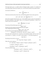
Figure
1
shows the vector relationships at the pump
inlet and outlet in terms of flow and velocity triangles.
The
pump head
is
the difference of
total
(static and dynamic)
heads between the pump’s inlet and outlet:
The
virtual
head (theoretical maximum head for a given set
of operating conditions) is given by:
u2c2
cos
a2
-
u,c,
cos
a,
H=
g
Lquid entering a
pump
usually moves along the impeller,
in
which case
al
=
90
degrees
and
the above relation becomes:
H=
(3)
Figure
1.
Flow
and velocity triangles
for
centrifugal
im-
pellers
[6].
where
V
represents the volumetric
rate
of flow through the
pump and
(2qb)
represents the cross-section of the flow
leaving the impeller.
Source
Cheremisinoff,
N.
P.,
Fluid
Flow
Handbook
Hous-
ton: Gulf Publishing Co.,
1984.
96
Rules
of
Thumb
for
Mechanical Engineers
Net Posltive Suction Head (NPSH) and Cavltation
The net positive suction head (NPSH) represents any
extra energy added
to
unit weight of liquid. Mathematically,
where pa is the atmospheric pressure, pv is the vapor pres-
sure of liquid,
y
is the specific weight of the liquid, z, is the
suction head, and
V
is the reference velocity. The NPSH
should always be above the vapor pressure of the liquid
being pumped.
This
is important for safe and reliable pump
operation.
NPSH
is given in feet of head above the vapor
pressure required at the pump centerline. The NPSH
re-
quirement increases as the pump capacity increases. Hence,
it is important
to
consider the range of flow requirements
during the pump selection time. However, too much
of
an
operational margin is not good either, because the pump ef-
ficiency at the low end of the design range will be lower
too. The available
NPSH
should be about 10 to
15
percent
higher than the required
NPSH,
no more and no less.
When a liquid flows into a space where its pressure is re-
duced to vapor pressure, it boils and vapor packets devel-
op in it. These bubbles
are
carried along until they meet a
region of higher pressure, where they collapse. This is
called
cavitation,
and creates a very high localized pressure
that causes pitting of
the
region. Cavitation lowers efficiency
of the fluid
machine.
It is always accompanied by noise and
vibrations. The cavitation parameter
Q
is defined
as:
Q=-
P-Pv
pv2
I2
(9)
where p is the absolute pressure at the point, pv is the
vapor pressure of liquid,
p
is the density of the liquid, and
V
is the reference velocity. This parameter is a nondimen-
sional parameter similar to the pressure coefficient.
A
hy-
draulic system is designed to prevent cavitation. The fol-
lowing points should be remembered when addressing
cavitation:
1.
Avoid low pressures if at
all
possible.
Pressurize
the
2.
Reduce the fluid temperature.
3.
Use a larger pipe diameter, and reduce minor losses
4.
Use special cavitation-resistant materials or coatings.
5.
Small
amounts of
air
entrained into the fluid systems
6.
The available NPSH should always be more than the
supply tank.
in
the pipe.
reduce the amount of cavitation damage.
required
NPSH.
Pumping Hydrocarbons and Other Fluids
It should be remembered that the NPSH specification by
a manufacturer is for use with cold water. It does not
change much for small changes in water temperature. But
for hydrocarbons, these values may be lowered
to
account
for the slower vapor release properties of such complex
or-
ganic liquids.
The head developed by a pump is independent of the liq-
uid being pumped. (The required horsepower, of course,
is
dependent on
the
fluid’s specific gravity.) Because of
this
independence, pump performance curves
from
water tests
are
applicable to other Newtonian fluids such
as
gasoline
Or alcohol.
The above independence is not true for high-viscosity
fluids. Therefore, correction factors have been experi-
mentally established for certain high-viscosity fluids.
These correction factors
(in
limited viscosity and size
ranges) may be applied to water curves under the under-
lying assumptions.
Pumps
and
Compressors
97
Recirculation
A recirculation problem is just the opposite of a cavita-
tion problem. Cavitation occurs when a pump is forced
to
operate at a flow rate higher than the intended rate. But if
the pump is operated at a
rate
considerably lower than the
one it was designed for,
this
causes
recirculation.
It results
in noise and vibration because
the
fluid energy is reduced
through fluid shear and internal
friction.
Pumping Power and
Eff
ilciency
A pump runner produces work
Qy3H,
where H
is
the
pump head. The energy added by the pump can be deter-
mined by writing Bernoulli's equation using the entry and
exit points of the pump:
The pump output is memured in
water
horsepowel;
or whp;
whereas
the
input horsepower
to
the pump shafl
is
called the
bruke
horsepower; or bhp. These
two
are
related by:
The difference between the
two
is called thefriction horse-
powel;
or fhp:
Large horsepower pumps
are
usually powered by
three-
phase induction motors,
whose
synchronous
speed
is:
Knowing the number of poles
Npoles
(always
an
even num-
ber), and the frequency fin cycledsecond
(Hz),
one
can
cal-
culate the synchronous speed. The actual
speed
is about
4
to
8
percent lower
than
the synchronous
speed.
This
dif-
ference is characterized
as
slip.
To
obtain
the
pump
oper-
ating speed, one could
use
either gear or belt drives.
Specific Speed of Pumps
The
specific
speed
of
a homologous unit is widely
used
as
the criterion
for
selection of a pump for a
specific
purpose.
It can
be
used to avoid cavitation or to select the most
ece
nomical pump for a given system layout. The
specific
speed
of a series is defined for
the
point of best efficiency-one
that delivers Unit discharge at unit head-and is given by:
Centrifugal pumps have low specific
speeds,
mixed
flow
pumps have higher values, and axial flow pumps have
even higher values.
The
specific
speed
of centrifugal pumps
may
vary between
1,000
to
15,000,
but values above
12,000
are
considered impractical. Whenever possible, a value
below
8,500
is usually recommended. Note that the rela-
tion above
is
dimensional
in
nature. Hence
the
value
of
N,
depends on the units of discharge and head involved. The
above values were given in
U.S.
customary units, where
Q
is in
gallons
per
minute
and
H
is
the
NPSH
infeet
offluid
NQ~I~
N,
=-
(13)
H3/4
98
Rules
of
Thumb
for
Mechanical Engineers
Two geometrically similar pumps
are
said
to
be homol-
ogous when
Q
-constunt
ND3
where the flow rate Q is equal
to
CdA Cd
being the
discharge coefficient,
A
is a reference area, and H is the
head. Rearranging terms in the equation above, the ho-
mologous condition may also
be
specified as:
H
-
=
Constant
N~D~
A
systematic Buckingham’s
Pi
Theorem analysis of
the
functional
form for the pump characteristics shows that the
nondimensional parameters for a pump may be expressed
as:
QHg
One might draw as many conclusions about pump
simil-
itude from the above functional relationship
as
the= are
re-
arrangements that can
be
made of the
terms.
As
an example,
because power is proportional to yQH, the nondimension-
al power
may
be
derived to be
(s)
Example
1
A
pump delivers
400
gaVmin at
3,000
rpm. How much
will it deliver at
2,500
rpm?
Solution.
Within design limits
of
the pump, the discharge
will be approximately proportional to the speed, Qz/Q1
=
N2/N1. Hence Qz
=
Q1. Nz/Nl=
400.2,500/3,000
=
333.33
gdmin. Similarly, for a given pump design, the head varies
as
the square of speed, and the power as the cube of speed.
Example
2
Develop a relation for power
P
in terms of speed
N
and
impeller diameter
D.
Solution:
From
our
pump similitude analysis earlier:
Q
=klND3andH=k2N21Y
From
our
knowledge in fluids:
P
=
“IQH
=
yklk2N3D5
=
k3yN3D5
(15)
Performance Curves
The power required to run a pump depends on two pur-
poses: first, to overcome
all
the losses in the related flow
circuits; and second, to supply the energy to the fluid for
the specified
task.
The first part of the power requirement
(to overcome losses) is called the brake horsepower (bhp),
and it is the absolute minimal required power even when
the volumetic flow rate is
zero.
The various losses that it
accounts for include mechanical friction losses in various
components, frictional losses at the impeller, losses due
to
fluid turbulence, and leakage losses. With increasing flow
rate
requirements, the bhp increases even
for
zero head. Fig-
ure
2
shows the head-discharge relations.
Figure
3
typifies a manufacturer’s performance curve of
a pump.
In
a carpet plot
like
this
one, for any
two
given val-
ues, the rest of the pumping variables
may
be
computed by
interpolation and careful extrapolation.
Figure
4
shows the effect of speed change on the pump’s
performance. Like Figures
2
and
3,
this
is again a typical
sample. For actual curves, one must consult the pump’s
manufacturer.
Q
Figure
2.
Head-discharge (H-Q) relationship.
Pumps
and
Compressors
99
0
9
0
8-
K
E,
‘
0
Y-
5
3.
:
s
U
.A
.I-
n-
w
I
0
N’
0
-
0-
eo
-
-
0
PO
40
80
80
100
120
140
160
180
zoo
CAPACITY
(GPM)
Figure
3.
Characteristics
of
a centrifugal pump
[q.
Saurces
Cheremisinoff,
N.
P.,
Fluid
Flow
Handbook.
Hous-
McAllister, E.
W.
(Ed.),
Pipe Line
Rules
of7hrnb
Hand-
book,
3rd
Ed.
Houston: Gulf Publishing
Co.,
1993.
ton: Gulf Publishing Co.,
1984.
Series and Parallel Pumping
Pumps may be operated in series, in parallel,
or
in any
series-parallel combination. When connected in series, the
total available head
is
the
sum
total of
all
heads at
a
given
rate
of
flow. When connected parallel, the total flow is the
sum total
of
all
flows at a given value
of
head.
In
other
words, series pumping is called
pressure
addih’ve;
and par-
allel pumping
is
dedflow
additive.
(See
Figures
5
and
6.)
The same rules
are
applied to determine
the
total head
or
flow
calculations for any series-parallel combination
HI
I
+Pumps
in Series
1
Pump
m
I
I
I
I
I
I I
100%
Q
0
Figure
5.
Effect
of
series pumping on
H-Q
cuwe.
HI
100%
I I
50%
100%
Q
0’
Figure
6.
Effect
of parallel pumping on
H-Q
cuwe.
of pumps. When connected in series, one pump’s discharge
is
connected
to
another’s
suction;
but
pumps
in
parallel
share
a
common suction and a common discharge line. It is
im-
portant to match the pumps
that
are in parallel
so
that they
develop
the
same head at
the
same flow
rate.
Multiple units are often used to allow a variety
of
pump-
ing conditions to be met without throttling, and therefore
wasting, power.
100
Rules
of
Thumb
for
Mechanical Engineers
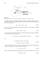
Design
Guidelines
Pipework
Table
2
lists common flow velocities in commercial use
and Table
3
lists recommended flow velocities based on the
The
fluids section
in
this book should be consulted
for
pipe
calculations,
but a
general
guideline
for
calculating
pipe
bore
size is:
Operating Performance
specific sravity
SG.
gal/min
Table
4
provides a
summary
of
operating
limitations
of
Borepi,
=
JE
m
=
/T
inches
(16)
different types
of
pumps.
Table
2
Common
Row
Velocities in Commercial Practice
Medium
later
'etrol
Iilr
iydro-
:arbons
4ir
~
Steam
Piping
Piston pumps
Feed
pumps of
steam
boilers
Piping for
condensate
and sludge
Gravel,
sand and other
drifted substances
Piping for cold
water
Piping for cold water
up to
50mm
diameter
up to 1DOmm diameter
up to 2Wmm diameter
above 200mm diameter
Piping for cooling water
Pressure water
Delivery piping in mines
Supply to water turbines
Municipal
water
mains,
main
faed
pipings
municipal water
Symm
suction
delivery
suction
deliwry
suction
delivery
delivsry
delivery
suction
NX.
NX.
max.
suction
delivery
Benzol.
gas
oil
Heavy
suction
Low-pressure piping
High-pressurcr piping
For steam
lines
up to 4MPa
Highgmssure
steam
Superheated
steam
Lowpressure heating
steam
Exhaust steam
Volocity mlrn
05-1.5
1
.0-2.0
0.3-0.5
2.0-2.5
0.3-0.5
1.0-2.0
0.5-2.0
1
.&3
.O
1.0
1.3
1.7
2.0
0.7-1
5
1
n-2.0
15M0.0
1.0-1.6
3.0
3.0-7.0
1
.o-2.0
0.5-1.2
1 n-2D
05-2.0
0.3-08
12-15
20-25
2040
30-80
39-80
10-15
15-40
Remarks
The piping
is
selected
accoi
ing
to
its
length.
A
lower
velocity
is
chosen with long
piping,
a
higher velocity
foi
short piping (does not appl
to
delivery
of
liquids con-
taining solid partic,les)
In special cases up to
5m/r
Low
head
High head
Normally
0.6
to
0.7mlsec
~-
According to viscosity
Velocities must be chosen
economically according to
the length
of
the piping
Pumps and Compressors
101
Table
3
Recommended
Flow
Velocities Based on Fluids
SG
Power
Drivrn
Pump
SG
=
1.0
I
SG
-
0.76
Pip.
Dumtor
Turbin
Drivon
Pumps
mm
SG
-
1.0
0.5
m/r
1.80
2.00
2.15
2.40
2.60
2.75
2
.a0
2.90
2.90
-
SG
-
0.76
SG.
hlr
6.00
6.50
7
1x1
8.00
8.50
9.00
9.25
9.50
9.50
-
-
inch
-
2
3
4
6
8
10
12
14
16
mlu
tlr
5.50
6.00
6.50
7.00
7.50
7.75
8.00
8.00
8.00
-
-
m/r
50
75
100
150
200
250
300
350
400
6.00
7
.00
8
.00
9
.oo
10.00
11.00
11.50
11.75
12.00
-
5.w
5.50
6.00
6.50
6.75
7
.oo
7 .00
7
.m
7 .00
1.50
1.70
1.80
2
.m
2.10
2.15
2.15
2.15
2.15
1.70
1
BO
2 .OO
2.15
2.30
2.35
2.40
2.40
2.40
1.80 7.00 2.10
2.10
8.00
2.40
2.40 9.00 2.75
2.75 10.00 3.00
3.00 11.25 3.40
3.25 12.00 3.66
3.50 12.50 380
3.60 13.W 4.00
3.65 13.00 4.00
and
over
Table
4
Summary
of
Operating Performances
of
Pumps
1-320
1-75
1-2500
65
65
0.1
-
1250
1-700
1-550
1-650
1
-5Ooo
1-750
0.3-25
1-45
0.3-25
1-6500
0.1
-
125
1-650
0-
1
0.1-6
0.1
-
125
950-
3X1V
950-
7.1X10'
950
-
2.4X10⁶
6.2X10'
6.2X10'
95-
1.2x10⁶
950-
6.7xlV
950-
5.2XlV
950-
6.2XlV
950-
4.8
X
106
950-
7.1X10'
285
-
2.4X10'
950-
4.3
X
10'
285
-
2.4X10'
950
-
6.2
X
106
95-
1.2XlV
950-
6.2XlV
0-950
95-
5.7X10'
95-
1.2XlV
150
425
335
73
120
1500
1675
1675
245
1830
215
1770
60
1830
1%
760
W)
34m
517000
34m
m
492
1394
1099
2.39
394
4922
54%
5495
804
6004
705
5807
197
6ow
39.4
2493
*i)
5oM8
74985
ux)4
uxn
493
MH
MH
MH
H
L
M
M
M
M
M
L
MH
M
H
M
M
L
L
M
M
2-6 6.6-20
650
2-6.7 6.6-22 430
2-7.6 6.6-25
650
1.2-6 3.9-20
650
1.5-7.6 4.9-25
650
2-6 6.6-20 430
2-6 6.6-20 430
2-6 6.6-20 430
1.01
0.67
1.01
1.01
1.01
0.67
0.67
0.67
1.01
0.67
0.67
0.17
0.67
0.67
1.01
0.17
1.71
1.71
1.46
20-80
455 851
20-75
455
851
30-90 205-455 401-851
20-75
205
401
20-80 455 851
20-70
540
1004
65-90 205-260401-500
40-75
20-85
25-90
20-80
10-50
40-75
30-75
65-85
55-85
55-85
-20
-20
455
851
0.3-6 1-20
650
a.3 6 1-20 430
2-6 1-20 430
2.4- 12 7.9-39.8 109
0.3-6.7 1-22 430
0.3-6 1-20 430
-2
6.6
650
2-2.5 6.6-8.2 109
345
653
26om
260
m
260
500
205
401
65
149
120 248
3.7
12 1100
4.6 15.1
1100
3.7
l2J 750
290
554
290
554
26om
260500
345
653
(=)
(W
-3
-9.8
150x106 150x106 50-80
-3
-9.8 150x106 150x106
50-80
0.1-320 95-
3400
3.OXlV
MH-moderately high; H-high; M-medium;
Uow
102
Rules
of
Thumb
for
Mechanical Engineers
Vacuum
Systems
Given two parameters, (a) rate of evacuation and
(b)
final
pressure to be realized, determine the size and number
of
pumps required for the job. The evacuation time is related
to the system parameters by the following equation:
2.3V
PI
Timemhutes
=
-
log,,
-
Q,
p*
where:
V
=
volume to be evacuated (liters),
Q,
=
effective
pump speed
(litedmin),
and PI and
Pz
are
initial and final
Note
that mechanical pumps are not suitable
for
pro-
ducing partial
pressures
less
than
about
lW3
torr.
Highly
spe
cialized pumps
are
used for the purpose.
pressures (torr).
Hoke
The following
formula
can
be
used
to
estimate the gener-
al noise level
of
a
centrifugal pump
within
plus
or
minus
2
dB.
where
Po
is total pressure rise across the impeller (bar),
Q
is the flow rate (m3/min), N, is the specific speed,
o
is
the
angular speed
(radsec),
and a2 is the impeller outside
ra-
dius (cm);
r,
is width of impeller at outlet (cm).
Noise may also
be
controlled by changing operating
conditions
of
the pump. The blade frequency noise levels
can change about
10
dB
by changing the operating point
of the pump. Minimum noise levels usually do happen at
flow rates around 15% above the design operating point.
Sources
Cheremisinoff,
N.
P.,
Fluid
Flow
Handbook
Hous-
Warring,
R.
H.,
Pumping
Manual,
.7th Ed. Houston: Gulf
ton: Gulf Publishing
Co.,
1984.
Publishing
Co.,
1984.
Pumps and Compressors
103
~~
Reciprocating
Pumps
A.
How
a
Reciprocating Pump
Works
A
reciprocating pump
is
a
positive
displacement mechanism
with
liquid discharge pressure being limited only by the
strength of the structural
parts.
Liquid volume or capacity
delivered is constant regardless of pressure, and is varied
only by speed changes.
Characteristics of a
GAS0
reciprocating pump are
1)
positii
displacement of liquid,
2)
high pulsations caused by the
sinusoidal motion of the piston,
3)
high volumetric efficien-
cy,
and
4)
low
pump maintenance cost.
8.
Plunger
or
Piston
Rod
Load
Plunger
or
piston
“rod
load”
is
an
important power end design
consideration for reciprocating pumps.
Rod
load is the force
caused
by
the liquid pressure acting on the face of the piston
or
plunger.
This
load
is
transmitted
directly to
the
power frame
assembly and is normally the limiting factor in determining
maximum discharge pressure ratings. This load is directly
proportional to the pump guage discharge pressure and pro-
poftional to the square of the plunger or piston diameter.
Occasionally, allowable liquid end pressures limit the
allowable
rod
load to a value below the design
rod
load. IT
IS
IMPORTANT THAT LIQUID END PRESSURES DO NOT
EXCEED PUBLISHED LIMITS.
C.
Calcuktlans
of
Volumetric Efficiency
Volumetric efficiency
(E,,)
is defined
as
the ratio of plunger
or
piston displacement to liquid displacement.
The
volumetric
efficiency calculation depends upon the internal configura-
tion of
each
individual liquid body, the piston size, and the
compressibility of the liquid being pumped.
D.
Tools
for
Liquid
Pulsation
Control,
Inlet
and
Discharge
Pulsation Control Tools (“PCT”, often referred to as
“dampeners” or “stabilizers”) are used on the inlet and
discharge piping to protect
the
pumping mechanism and
associated piping by reducing the high pulsations within the
liquid caused by the motions of the slidercrank mechanism.
A
properly located and charged pulsation control tool may
reduce
the length of pipe
used
in
the acceleration head equa-
tion to a value of
5
to
15
nominal pipe diameters. Figure
5
is a suggested piping system for power pumps. The pulsa-
tion control tools are specially required to compensate
for
in-
adequately designed or oldladapted supply and discharge
systems.
E. Acceleration
Head
Whenever a column of liquid is accelerated
or
decelerated,
pressure
surges
exist.
This
condition is found on the inlet side
of the pump
as
well
as
the discharge side. Not
only
can the
surges cause vibration in the inlet line, but they can restrict
and impede
the
flow of liquid and cause incomplete filling
of the inlet valve chamber. The magnitude
of
the surges and
how they
will
react in the system is impossible to predict
without an extremely complex and costly analysis
of
the
system. Since the behavior of the natural frequencies in the
system
is
not easily predictable,
as
much of the surge as
possible must be eliminated at the source. Proper installa-
tion of an inlet pulsation control PCT will absorb a large
percentage of the surge before
it
can travel into the system.
The function of the PCT is to absorb the “peak” of the surge
and
feed
it back at the
low
part of the
cyde.
The best posi-
tion for the PCT is
in
the liquid supply line
as
close to the
pump
as
possible, or attached to the blind flange side of the
pump inlet. In either location, the surges
will
be dampened
and harmful vibrations reduced.
RECIPROCATING
PUMPS
FLOW
CHARACTERISTICS
A
100%
0%
0
60
120 180
240
300
360
Crankshaft Angle (Degree)
100%
‘
‘
\/
f/
p.
\
r’
‘,
#
4
’
0%
I
0
60
120
180
240
300
360
Crankshaft Angle (Degree)
DUPLEX DOUBLE-ACTING
Average
Flow
-
100%
Maximum
Flow
-
100%
+
Minimum
Flow
-
100%
-
Total
Flow
Var.
-
46%
TRIPLEX SINGLE-ACTING
Average
Flow
-
100%
Maximum
Flow
-
100%
+
Minimum
Flow
-
100%
-
Total
Flow
Var.
-
23%
24%
22%
6%
17%
104
Rules
of
Thumb for Mechanical Engineers
100%
QUINTUPLEX SINGLE-ACTING
Average
Flow
-
100%
Maximum
Flow
-
100%
+
2%
Minimum
Flow
-
1000/0
-
5%
Total
Flow
Var.
-
7%
0%
0
60
1
20 180
240
300 360
Crankshaft Angle (Degree)
1000/,
0%
SEPTUPLEX SINGLE-ACTING
Average
Flow
-
100%
Maximum
Flow
-
100%
+
1.2%
Minimum
Flow
-
100%
-
2.6%
Total
Flow
Var.
-
3.8%
0
60
1
20
1
a0
240
300
360
Crankshaft Angle (Degree)
NONUPLEX SINGLE-ACTING
Average
Flow
-
100%
Maximum
Flow
-
100%
+
0.6%
Minimum
Flow
-
100%
-
$1.5%
Total
Flow
Var.
-
2.1%
0
60
120
180
240
300
360
Crankshaft Angle (Degree)
REQUIRED FORMULAE AND DEFINITIONS
Acceleration
Hesd
ha
P
LVNC
V
=
GPM
Kg (2.45)
(D)
Where
=
Acceleration head (in feet)
P
=
Length of liquid supply line (in line)
V
=
Average velocity in liquid supply line (in fps)
N
=
Pump speed (revolutions per minute)
C
=
Constant depending on the type of pump
C
=
0.200
for simplex double-acting
=
0.200
for duplex single-acting
=
0.115 for duplex double-acting
=
0.066
for triplex single or double-acting
=
0.040
for quintuplex single or double-acting
=
0.028 for septuplex, single
or
doubleacting
=
0.022 for nonuplex, single or double-acting
K
=
Liquid compressibility factor
K
=
2.5
For relatively compressible liquids
K
=
2.0 For most other hydrocarbons
K
=
1.5 For amine, glycol and water
K
=
1.4 For liquids with almost no compressibility
(hot water)
g
=
Gravitational constant
=
32.2
Wsec2
d
=
Inside diameter
of
pipe (inches)
Stroke
One complete uni-directional motion
of
piston
or
plunger.
Stroke length is expressed in inches.
(ethane, hot oil)
Pump Capacity
(Q)
The capacity of a reciprocating pump is the total volume
through-put per unit of time at suction conditions. It includes
both liquid and any dissolved or entrained gases at the stated
operating conditions. The standard unit of pump capacity is
the
U.S.
gallon per minute.
Pump Displacement
(D)
The displacement of a reciprocating pump is the volume
swept by all pistons or plungers per unit time. Deduction for
piston rod volume is made on double acting piston type
pumps when calculating displacement. The standard unit of
pump displacement is the
U.S.
gallon per minute.
For single-acting pumps:
D
=
Asnm
-
231
For double-acting piston pumps:
D
-
(2A
-
a) snm
231
Where
A
=
Plunger or piston area, square inch
a
=
Piston
rod
cross-sectional area, square inch
s
=
Stroke length, inch
n
=
RPM
of
crankshaft
m
E
Number
of
pistons or plungers
(double-acting pumps)