Safety at Work 6 E Part 11 docx
Bạn đang xem bản rút gọn của tài liệu. Xem và tải ngay bản đầy đủ của tài liệu tại đây (567.37 KB, 60 trang )
Workplace pollution, heat and ventilation 575
3.6.4 Ventilation control of a workplace environment
As a result of the COSHH regulations there is a legal duty to control
substances that are hazardous to health. The Approved Code of Practice
(ACOP)
7
associated with these regulations sets out in order the methods
that should be used to achieve adequate control. Extract and dilution
ventilation are two of the methods mentioned. These regulations also
require the measurement of the performance of any ventilation systems
that control substances that are hazardous to health. The places where
measurements are required to be taken are listed in para. 61 of the ACOP.
3.6.4.1 Extract ventilation
In the design of extract ventilation it is important to create, at the point of
release of the pollutants, an air velocity sufficiently strong to capture and
draw the pollutants into the ducting. This is known as the capture
velocity and can be as low as 0.25 m/s for pollutants released gently into
still air such as the vapour from a degreasing tank or as much as 10 m/s
or more for heavy particles released at a high velocity from a device such
as a grinding wheel. The capturing device can be a hood, a slot or an
enclosure to suit the layout of the workplace and the nature of the work
but the more enclosure that is provided and the closer to the point of
emission it is placed, the more effective will be the capture.
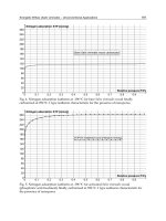
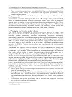
Difficulty can be experienced with moving sources of pollution such as
the particles from hand-held power saws and grinders. In these
circumstances high velocity low volume extractors can be fitted to the
tools using flexible tubing of 25–50 mm diameter to draw the particle-
laden air to a cleaner which contains a high efficiency filter and a strong
suction fan (Figure 3.6.4).
Figure 3.6.4 High velocity low volume extractor. (Courtesy BVC Ltd)
576 Safety at Work
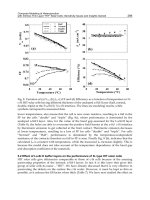
Hoods attached to larger diameter flexible tubing can be used for
extraction from the larger moving sources such as welding over wide
areas, but owing to the higher weight of these devices some form of
movable support system is required (Figure 3.6.5).
When siting a capture hood or slot, advantage should be taken of the
natural movement of the pollutants as they are released. For example, hot
substances and gases are lighter than air and tend to rise, thus overhead
capture might be most suitable, whereas some solvent vapours when in
concentrated form are heavier than air and tend to roll along horizontal
surfaces, so capture points are best placed at the side. Care must be taken
to ensure that all contaminants are drawn away from the breathing zone
of the worker – this particularly applies to places where workers have to
lean over or get close to their work. It is important to note that whenever
extract ventilation is exhausted outside, a suitably heated supply of
make-up air must be provided to replace that volume of air discarded.
There are established criteria for the design of extract systems
8
.
3.6.4.2 Dilution ventilation
This method of ventilation is suitable for pollutants that are non-toxic and
are released gently at low concentrations and should be resorted to only
if it is impossible to fit an extractor to the work station. It should not be
used if the pollutants are released in a pulsating or intermittent way or if
they are toxic. The volume flow rate of air required to be provided must
be calculated taking into account the volume of the pollutants released,
Figure 3.6.5 Portable collecting hood. (Courtesy Myson Marketing Services Ltd)
Workplace pollution, heat and ventilation 577
the concentration permitted in the workplace and a factor of safety which
allows for the layout of the room, the airflow patterns created by the
ventilation system, the toxicity of the pollutant and the steadiness of its
release
9,10
.
Hourly air change rates are sometimes quoted to provide a degree of
dilution ventilation. The volume flow rate of air in cubic metres per hour
is calculated by multiplying the volume of the room in cubic metres by
the number of air changes recommended. There are recommended air
change rates for a range of situations
11
.
3.6.5 Assessment of performance of ventilation systems
In addition to the testing of the airborne concentrations of pollutants, it is
necessary, and indeed is a requirement of COSHH, to check airflows and
pressures created in a ventilation system to ensure that it is working to its
designed performance by measuring:
1 Capture velocity.
2 Air volume flow rates in various places in the system.
3 The pressure losses across filters and other fittings and the pressures
developed by fans.
The design value of these items should be specified by the maker of the
equipment. Therefore, instruments and devices are required to:
1 Trace and visualise airflow patterns.
2 Measure air velocities in various places.
3 Measure air pressure differences.
Figure 3.6.6 Smoke tube
578 Safety at Work
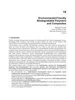
Figure 3.6.7 Vane anemometer. (Courtesy Air Flow Developments Ltd)
Workplace pollution, heat and ventilation 579
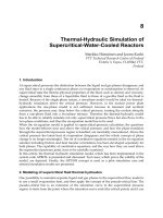
Air flow patterns can be shown by tracers from ‘smoke tubes’ which
produce a plume of smoke when air is ‘puffed’ through them (Figure 3.6.6).
For workplaces where airborne particles are released it is possible to
visualise the movement of the particles by use of a dust lamp. This shines a
strong parallel beam of light through the dust cloud highlighting the
particles in the same way that the sun’s rays do in a darkened room.
Air velocities can be measured by a variety of instruments but vane
anemometers and heated head (hot wire or thermistor) air meters are the
most common. Vane anemometers (Figure 3.6.7) have a rotating ‘windmill’
type head coupled to a meter and are most suitable for use in open areas
such as large hoods and tunnels. The heated head type of air meter (Figure
3.6.8) is more suitable for inserting into ducting and small slots and is more
versatile than the vane anemometers except that it is unsuitable for use in
areas where flammable gases and vapours are released. Most air flow
measuring instruments require checking and calibration from time to time.
One instrument which requires no calibration but is only effective in
measuring velocities above approximately 3 m/s is the pitot-static tube
which, in conjunction with a suitable pressure gauge, measures the
velocity component of the pressure of the moving air which can be
converted to air velocity by means of the simple formula:
p
v
=
1
⁄
2
v
2
or v =
ͱ
2p
v
where p
v
= velocity pressure (N/m
2
or Pa); = air density (usually taken
to be 1.2 kg/m
3
for most ventilation situations); and v = air velocity
(m/s).
Figure 3.6.8 Heated head air meter. (Courtesy Airflow Developments Ltd)
580 Safety at Work
Pitot-static tubes are small in diameter and can easily be inserted into
ducting.
All the above air velocity measuring instruments need to be placed
carefully in an airstream so that their axes are parallel to the stream lines;
any deviation from this will give errors.
Differences in air pressure can be measured by a manometer or U-tube
gauges filled with water or paraffin, placed either vertically or, for greater
accuracy, inclined. If the two limbs of the gauge are coupled by flexible
plastic or rubber tubing to either side of the place to be measured, such
as a fan or a filter, then the difference in height between the two columns
of the tube indicates the pressure difference. Pressure tappings in
ductings must be at right angles to the air flow to measure what is termed
‘static pressure’.
Liquid-filled gauges are prone to spills and the inclusion of bubbles
and before use must be carefully levelled and zeroed. Diaphragm
pressure gauges avoid these problems but need to be checked for
accuracy from time to time. Electronic pressure gauges are also
available.
Airflow measuring techniques vary to suit the application
2
.
References
1. ACGIH, Air Sampling Instruments, 8th edn, American Conference of Governmental
Industrial Hygienists, Cincinnati, Ohio (1995)
2. Gill, F.S. and Ashton, I., Monitoring for Health Hazards at Work, Chapter 4, ‘Ventilation’,
Blackwell Science, Oxford (2000)
3. Youle, A., ‘The thermal environment’ chapter in Occupational Hygiene (Eds Harrington,
J.M. and Gardiner, J., Blackwell Science, Oxford (1995)
4. Harrington, J.M., Gill, F.S., Aw, T.C. and Gardiner, K., Occupational Health Pocket
Consultant, Blackwell Science, Oxford (1998)
5. Health and Safety Executive, Guidance Note EH40, Occupational Exposure Limits, HSE
Books, Sudbury, latest issue
6. ACGIH, Threshold Limit Values for Chemical Substances and Physical Agents in the Workroom
Environment, American Conference of Governmental Industrial Hygienists, Cincinnati,
Ohio (2001)
7. Health and Safety Executive, Legal series booklet no. L 5, General COSHH ACOP
(Control of substances hazardous to health), Carcinogens ACOP (Control of carcinogenic
substances) and Biological agents (Control of biological agents). Control of Substances
Hazardous to Health Regulations 2002. Approved Code of Practice, HSE Books, Sudbury
(2002)
8. British Occupational Hygiene Society, Technical Guide No. 7, Controlling Airborne
Contaminants in the Workplace, Science Reviews Ltd, Leeds (1987)
9. Gill, F.S., ‘Ventilation’ chapter in Occupational Hygiene (Eds Harrington, J.M. and
Gardiner, K), Blackwell Scientific, Oxford (1995)
10. ACGIH, Industrial Ventilation, 22nd edn, American Conference of Governmental
Industrial Hygienists, Cincinnati, Ohio (1995)
11. Daly, B. B., Woods Practical Guide to Fan Engineering, chapter 2, Woods of Colchester Ltd
(1978)
12. EEC Council Regulation no. EEC/793/93 on the evaluation and control of the risks of
existing substances, EC, Luxembourg (1993)
Further reading
Ashton, I. and Gill, F.S., Monitoring for Health Hazards at Work, Blackwell Science, Oxford
(2000)
581
Chapter 3.7
Lighting
E. G. Hooper and updated by Jonathan David
3.7.1 Introduction
Lighting plays an important role in health and safety, and lighting
requirements are increasingly being included in legislation and stan-
dards, albeit that primary legislation tends to specify that lighting shall be
‘sufficient and suitable’. Legislation whose content has lighting in its
requirements includes that for the workplace
1
, work equipment
2
, docks
3
,
the use of electricity
4
and display screen equipment
5
. Most people prefer
to work in daylight making the best possible use of natural light, though
this may not always be the most energy efficient approach. However, for
many working environments natural light is often insufficient for the
whole working day, and in deeper spaces may not be adequate at any
time. It therefore has to be supplemented or replaced by artificial lighting,
usually electric lighting. The quality of the lighting installation can have
a significant effect on health, productivity and the pleasantness of interior
spaces in addition to its role in safety.
3.7.2 The eye
The front of the eye comprises, in simple terms, a lens to control the
focusing point within the eye and an iris to control the light entering the
eye. The back of the eye contains the retina which is made up of rod and
cone shaped cells which are sensitive to light and are linked by optic
nerves to the brain. The lens ensures that the image being viewed is
focused on the retina and the iris controls the amount of light. Different
cells in the retina are sensitive to different colours, and while the central
part of the retina, known as the fovea, is sensitive to colours the
peripheral areas are sensitive only to light intensity. A result is that colour
vision disappears at low light levels.
582 Safety at Work
3.7.3 Eye conditions
The eye is a very delicate and sensitive structure and is subject to a
number of disorders and injuries requiring skilled treatment: some of
these disorders are mentioned briefly below.
Conjunctivitis is an inflamed condition of the conjunctiva (the mucous
membrane covering the eyeball) caused by exposure to dust and fume
and occasionally to micro-organisms.
Eye strain, so called, is caused by subjecting the eye to excessively
bright light or glare; the term is also used colloquially to describe the
symptoms of uncorrected refractive errors. There is no evidence that the
eye can be ‘strained’ simply by being used normally.
Accommodation is a term for the ability of the eye to alter its refractive
powers and to adjust for near or distant vision. As the eye ages the lens
loses its elasticity and hence its accommodation, thus affecting the ability
to read and requiring corrective spectacles. In addition to this ageing
process defects in accommodation can occur early in life, such as by the
presence of conditions known as
1 astigmatism due to the cornea of the eye being unequally curved and
affecting focus;
2 hypermetropia, or long sight, in which the eyeball is too short; and
3 myopia, or short sight, in which the eyeball is too long.
These defects can usually be corrected by spectacles.
Nystagmus is an involuntary lateral or up and down oscillating and
flickering movement of the eyeball, and is a symptom of the nervous
system observed in such occupations as mining.
Double vision is the inability of both eyes to focus in a co-ordinated way
on an object usually caused by some defect in the eye muscles. It can be
due to a specific eye injury, to tiredness or be a symptom of some illness.
It may be a momentary phenomenon or may last for longer periods.
Colour blindness is a common disorder where it is difficult to distinguish
between certain colours. The most common defect is red/green blindness
and may be of a minor character where red merely loses some of its
brilliance, or of a more serious kind where bright greens and reds appear
as one and the same colour – a dangerous condition in occupations
requiring the ability to react to green and red signals or to respond to
colour coding of pipework or electrical cables.
Temporary blindness may be due to some illness but it can occur in the
following circumstances:
1 Involuntary closure of the eyelids due to glare.
2 Impairment of vision due to exposure to rapid changes in light
intensity and to poor dark adaptation or to excessively high light
levels.
The act of seeing requires some human effort which is related to the
environmental conditions. Even with good eyesight a person will find it
difficult to see properly if the illumination (level of lighting) is not
Lighting 583
adequate for the task involved, e.g. for the reading of small print or
working to fine detail. But no standard of lighting, however well planned,
can correct defective vision and anyone with suspected visual disability
should be encouraged to undergo an eye test and, if advised, wear
corrective spectacles. Legislation now requires that employees working
with visual display terminals (vdts) be offered free eye tests by their
employers if they so request
5
.
3.7.4 Definitions
6
The following terms are used in connection with illumination:
Candela (cd) is the SI unit of luminous intensity, i.e. the measure
describing the power of a light source to emit light.
Lumen (lm) is the unit of luminous flux used to describe the quantity of
light emitted by a source or received by a surface.
Illuminance (symbol E, unit lux) is the luminous flux density of a
surface, i.e. the amount of light falling on a unit area of a surface, 1 lux =
1 lm/m
2
.
Maintained illuminance is the average illuminance over the reference
surface at the time maintenance has to be carried out. It is the level below
which the illuminance should not drop at any time in the life of the
installation.
Luminance (symbol L, unit cd/m
2
) is the physical measure of the
stimulus which produces the subjective sensation of brightness, meas-
ured by the luminous intensity of the light emitted or reflected in a given
direction from a surface element divided by the projected area of the
element in the same direction.
Luminance = (illuminance ϫ reflection factor)/
Brightness is the subjective response to luminance in the field of view
dependent on the adaptation of the eye.
Reflectance factor is the ratio of the luminous flux reflected from a
surface to the luminous flux incident upon it.
Incandescent lamp is a lamp where the passage of a current through a
filament (usually coiled) raises its temperature to white heat (incandes-
cence), giving out light. Oxidisation within the glass bulb is slowed down
by the presence of an inert gas or vacuum sealing of the bulb. The most
commonly used lamp is the General Service Lamp, but there also exists a
wide range of decorative lamps. Higher efficiency incandescent lamps
can be created by including in the bulb a small amount of a halogen
element such as iodine or bromine. In such lamps, usually known as
tungsten-halogen lamps, the halogen combines with the tungsten and is
deposited on the inside of the bulb. When this compound approaches the
filament it decomposes, owing to the high temperature, and deposits the
tungsten back on the filament.
The European Commission has developed a scheme for energy rating
of lamps commonly used for domestic purposes. This does not apply to
other lamp types or lamps sold to commercial and industrial
organisations.
584 Safety at Work
Electric discharge lamp is a lamp where an arc is created between two
electrodes within a sealed and partially evacuated transparent tube.
Depending on the format of the tube, the remaining gas pressure and the
trace elements that are introduced, numerous different types of lamp can
be produced:
1 Low pressure sodium lamp used chiefly for road lighting which produces
a monochromatic yellow light but is highly efficient. However,
increased knowledge of the performance of the eye at very low light
levels has led to a questioning of whether the low pressure sodium
lamp is as effective as previously thought.
2 Low pressure mercury lamp – the ubiquitious ‘fluorescent tube’ in which
the ultraviolet radiation from the discharge is converted to visible light
by means of a fluorescent coating (phosphor) on the inside of the tube.
Fluorescent lamps come in various forms:
(a) Linear lamps, both full size (600–2400 mm long) and miniature (less
than 600 mm long), come in a range of wattages and efficiencies as
well as a range of whites and colours. Traditionally, while
halophosphate phosphors were used, there was a trade-off between
colour quality and efficiency; with modern triphosphor and multi-
band lamps this is no longer the case. T12 (38 mm diameter) lamps
have largely been superseded by T8 (26 mm) or T5 (15.5 mm) lamps
offering higher efficacies and better light control. T5 lamps are
offered in two specific ranges: standard and high output. A recent
development is T2 (6.5 mm diameter) lamps which offer high efficacy
but require dedicated control gear and careful light control. These
were originally offered for specialist applications such as under-shelf
lighting in retail shops but are finding wider applications.
(b) Compact lamps, in both retrofit designs intended for existing
installations and for newer installations when compatibility with
other lamp types does not matter, come in a variety of formats and
ratings from 5 W to 55 W.
3 High pressure mercury lamp is a largely obsolete type of lamp where light
is produced by means of a discharge within an arc tube doped with
mercury. The light tends to be bluish in colour and efficiency is lower
than other currently used types of discharge lamp. It is still popular in
some tropical countries because of its ‘cool’ light.
4 High pressure sodium lamp is similar to a mercury lamp except that the
arc tube is doped with sodium giving a yellow light whose colour
rendering and whiteness depend on the vapour pressure within the
tube.
5 Metal halide lamp is similar to the mercury lamp except that the mercury
is replaced by a carefully designed cocktail of rare earth elements.
Colour rendering can be very good and efficiency is high with
additional coloured light being generated by the suitable choice of
elements in the cocktail. The small arc tube means that light control can
be very good. There can be problems with colour stability over the life
of the tube.
Induction lamp in which the lamp itself is simply a glass tube containing
an inert gas and coated on the inside with a phosphor to convert the
Lighting 585
ultraviolet radiation to visible light. The discharge which takes place in
the tube is initiated by an electric or microwave field outside the lamp by
equipment containing a powerful electromagnet or a magnetron. Differ-
ent manufacturers have adopted different physical formats. Efficiency is
fairly high and, because there are no moving parts in the tube, lamp life
can be extremely long making the lamp ideal where maintenance access
is difficult.
Luminaire is a general term for all the apparatus necessary to provide a
lighting effect. It usually includes all components for the mounting and
protection of lamps, controlling the light distribution and connecting
them to the power supply, i.e. the whole lighting fitting. Occasionally part
of the control gear may be mounted remote from the luminaire.
3.7.5 Types of lighting
The selection of the source of light appropriate to the circumstances
depends on several factors. It is important to consider efficiency, ease
of installation, costs of installation and running, maintenance, lamp life
characteristics, size, robustness and heat and colour output. The
efficiency of any lamp (often termed efficacy) can be expressed in terms
of light output per unit of electricity used (lumens per watt). Generally
speaking, incandescent lamps are less efficient than discharge
sources.
Type of lamp Lumens per watt
Incandescent lamps Up to 15
Tungsten halogen Up to 22
High pressure sodium Up to 140
Metal halide Up to 100
Fluorescent Up to 100
Compact fluorescent Up to 85
Induction Up to 65
Low pressure sodium Up to 200
Note that smaller ratings are usually less efficient than larger ratings and
that the above figures do not include losses within the control gear
needed for all but incandescent lamps. Note also that control gear losses
can differ markedly between brands. A rating scheme for efficiency of
ballasts for fluorescent lamps has been introduced in Europe
7
.
In any choice between incandescent and the other types of lamp the
total lighting costs must take into account not only running costs but also
installation and replacement costs. Incandescent lamps are much cheaper
to buy and install, they give out light immediately they are switched on
and they can be dimmed easily, but they are more expensive to run and
have short lives, thus increasing maintenance costs. High pressure
discharge and fluorescent lamps cost more to install but their greater
efficiency and longer lives make them more cost effective for general
lighting. Linear and compact fluorescent lamps come to full light output
586 Safety at Work
reasonably quickly but discharge lamps need some time to strike and
then achieve maximum light output, and may need several minutes to
cool before they will restrike if accidentally extinguished. Hot restrike is
possible for some lamps but is expensive.
In larger places of work the choice is often between discharge and
fluorescent lamps. Where colour performance is important the sodium
lamp, with its rather warm golden effect, may not be suitable and the
choice is usually between the tubular fluorescent lamp and the metal
halide lamp. A limitation of the fluorescent lamp is the restricted loading
per point (i.e. more lamps are required per unit surface area) and in
certain workshops where luminaire positioning at heights is required (in
workshops with overhead travelling cranes for example) the high
pressure discharge lamp with its higher loading per point (generally up
to 1 kW) is often selected. Figure 3.7.1 shows factory lighting where fine
work and colour rendering are important.
3.7.6 Illuminances
The illuminance (lighting level) required depends upon such things as the
visual performance necessary for the tasks involved and general comfort
and amenity requirements. The average illuminance out of doors in the
UK is about 5000 lux on a cloudy day, but may be 10 times that on a sunny
Figure 3.7.1 Factory lighting where fine work is carried out and colour rendering is
important, making use of reflector luminaires with tubular fluorescent lamps.
(Courtesy Lighting Industry Federation)
Lighting 587
day. Inside a workplace, the illuminance from natural light at, say, a desk
next to a window, will probably be only about 20% of the value obtaining
outdoors. As working areas get further from windows the natural light
produces illuminance values of perhaps only 1 to 10% of outdoor values
so requires supplementing by artificial lighting. The normal way of
expressing the effectiveness with which daylight reaches an interior is
termed daylight factor
8
.
In normal practice, decisions should be based on the recommendations
of the Code for Lighting, produced by the Society of Light and Lighting,
part of the Chartered Institution of Building Service Engineers
9
(CIBSE)
or the recommendations of a similar national body. Most such rec-
ommendations are now based on European standards and/or inter-
national recommendations. Typical values of maintained illuminance for
certain locations and tasks are given below but for detailed information,
for particular industries and tasks, reference should be made to the
Society. Guidance and advice can be obtained from an HSE publication
10
and the Lighting Industry Federation
12
. However, HSE requirements deal
only with health and safety issues, whereas the Society of Light and
Lighting recommendations also take account of cost effectiveness,
productivity and amenity.
Although the term maintained illuminance represents levels that are
good for general purposes, increases over the figures given may be
necessary where tasks of high visual difficulty are undertaken, or low
reflection or contrast are present, or where the location is a windowless
interior. The Code for Lighting
9
gives criteria on which such adjustments
can be based.
Maintained
Location and task illuminance (lx)
Storage areas, plant rooms, entrance halls etc. 150–200
Rough machinery and assembling, conference
rooms, typing rooms, canteens, control rooms,
wood machinery, cold strip mills, weaving and
spinning etc. 300–400
Routine office work, medium machinery and
assembly etc. 500
Spaces containing vdts used regularly as part of
office tasks. 300–500
Demanding work such as in drawing offices,
inspection of medium machinery etc. 750
Fine work requiring colour discrimination, textile
processing, and fine machinery and assembly etc. 1000
Very fine work, e.g. hand engraving and
inspection of fine machinery and assembly 1500
A new requirement, emanating from European standards, is a
minimum illuminance of 200 lx for any continuously occupied interior.
588 Safety at Work
For a discussion on average maintained illuminances, minimum
measured illuminances and for maximum ratio of illuminances between
working and adjacent areas see reference 9.
European standards are being developed for several areas of lighting
design. These will normally be taken account of in any revisions of
guidance documents such as the Society of Light and Lighting Code for
Lighting
9
. However, other than a few mandated standards, European
standards are voluntary documents, and there is no compulsion on
national lighting societies to adopt them. In addition, there is nothing to
stop a national society adopting standards higher than those in a
European standard, since documents from professional bodies normally
carry no legal status.
3.7.6.1 Maintenance of lighting equipment
Dust, dirt and use will progressively reduce the light output of lamps and
luminaires. Attention to good general cleaning and maintenance, and a
realistic lamp replacement policy will help maintain the illuminance
within recommendations. The expected maintenance regime is an
essential factor in calculating the number of luminaires required for an
installation. The maintenance regime appropriate to a building will
depend on the activities carried out, the amount of dirt and dust carried
in from outside and the type of lighting equipment in use. Some modern
lamps lose light output much more slowly than older types, though
luminaires will soil just as quickly.
3.7.7 Factors affecting the quality of lighting
The eye has the faculty of adjusting itself to various conditions and to
discriminating between detail and objects. This visual capacity takes time
to adjust to changing conditions as, for example, when leaving a brightly
lit workroom for a darkened passage. Sudden changes of illuminance and
excessive contrast between bright and dark areas of a workplace should
be avoided.
A recent problem, resulting from the introduction of word-processors
and other equipment using vdts, is the effect on eye discomfort and
general well being of viewing screens for extended periods of time.
Problems can be increased if the contrast between the screen and paper
task is too great, if there is excessive contrast between the screen and
background field of view, and if there are reflections of bright objects
(luminaires, windows or even white shirts) in the screen. Lighting
installations in such areas must comply with the requirements of the DSE
Regulations
5
. The CIBSE has published specific guidance in this area
11
and has recently updated it by means of an addendum to take account of
trends in software and VDU screens.
Lighting 589
3.7.7.1 Glare
Glare causes discomfort or impairment of vision and is usually divided
into three aspects, i.e. disability glare, discomfort glare, and reflected
glare.
It is referred to as disability glare if it impairs the ability to see clearly
without necessarily causing personal discomfort. The glare caused by the
undipped headlamps of an approaching car is an example of this.
Discomfort glare causes visual discomfort without necessarily impair-
ing the ability to see and may occur from unscreened windows in bright
sunlight or when over-bright or unshaded lamps in the workplace are
significantly brighter than the surfaces against which they are viewed,
e.g. the ceiling or walls.
Reflected glare, which can be disability glare or discomfort glare, is the
effect of light reflected from a shiny or polished non-matt surface. The
visual effect may be reduction of contrast, or distortion, and can be both
irritating and, in certain workplaces, dangerous.
3.7.7.2 Glare indices
For many years in the UK, a glare index system has been in use for
quantifying the effects of direct glare. It is also in use in certain other
countries.
This is now being replaced by the international Unified Glare Rating
System (UGR) which has been adopted as standard in Europe. The
numerical values will normally be much the same but the derivation
formula is different:
UGR = 8 log [(0.25/L
b
) x ⌺ (L
2
/P
2
)]
where L
b
= background luminance
L = luminance of the luminous parts of each luminaire in the
direction of the observer’s eye
= solid angle subtended by the luminous parts of each luminaire
at the observer’s eye
P = Guth position index for each luminaire
A set of tables, based on this formula, has been produced by the Society
of Light and Lighting for a range of situations, types of luminaire, etc.,
and these should be referred to for specific advice
9
. Figures above the
recommended levels for a given location may lead to visual
discomfort.
Separate advice has been published
11
on reducing glare in premises
where VDUs are in use. This includes factories and workshops as well as
offices. Draft EU standards for lighting use the Unified Glare Rating
system in place of the glare index. These standards are not mandatory
except in contracts involving the public sector.
590 Safety at Work
3.7.7.3 Protection from glare
The most common cause of glare results from looking directly at
unscreened lamps from normal viewing angles. Any form of diffuser or
louvre fitted over the lamp, or a suitably placed reflector used as a screen
will help to reduce the effect of glare from a lamp. The minimum
screening angle below the horizontal should be about 20°, though greater
angles are specified for areas containing vdts
11
. Reflected glare can only
really be eliminated by changing the offending shiny surface for a matt
one, or by adjusting the relative positions of light source, reflective
surface and viewer.
Glare from sunlight coming through windows can be reduced by using
exterior or interior blinds but this reduces the amount of natural lighting.
It may be more effective to rearrange the workplace so that the windows
are not in the normal direct field of view.
3.7.7.4 Effect of shadow
Shadow will affect the amount of illumination, and its impact on people
in working areas will depend on the task being performed, and on the
Figure 3.7.2 Factory lighting of correct illuminance, free from shadow and glare,
making use of high pressure discharge lamps. (Courtesy Thorn Lighting Ltd)
Lighting 591
disposition of desks, work benches etc. The remedy is to use physically
large luminaires (not necessarily with higher light outputs) or to increase
their number. Figure 3.7.2 illustrates factory lighting where the illumi-
nance is to recommended standards.
3.7.7.5 Stroboscopic effect
The earlier type of tubular fluorescent lamp and discharge lamp were
criticised because of the possibility of a stroboscopic effect. The light
output from most lamps shows a cyclical variation with the alternating
current, although in most circumstances this is not noticeable. However,
it can cause a piece of rotating machinery to appear stationary or to be
rotating slowly when, in fact, it is rotating at many times a second. This
can be extremely dangerous. However, with modern fluorescent lamps
and some discharge lamps the problem has been minimised by reducing
the flicker effect. Where stroboscopic effects pose a particular danger they
can be eliminated since it is possible to operate linear fluorescent and
compact fluorescent lamps on electronic control gear at high frequency
which both minimises the cyclic variation of light output and changes its
frequency so that it is no longer visible as flicker. Alternatively, in most
industrial and many commercial buildings it is possible to connect
successive luminaires to the three phases of the power supply, which
eliminates most flicker and stroboscopic effects.
3.7.7.6 Colour effect
The reflection of light falling on a coloured surface produces a coloured
effect in which the amount of colour reflected depends upon the light
source and the colour of the surface. For example, a red surface will only
appear red if the incident light falling upon it contains red: under the
almost monochromatic yellow of sodium street lighting, for example, a
red surface will appear brown. The choice of lamp is important if colour
effect or ‘warm’ or ‘cool’ effect is required and can be as important a
consideration as the illuminance itself. Where accurate colour judgements
have to be made the illuminance should be not less than 1000 lux and it
may be appropriate to use either lamps whose colour rendering index is
above 90 (CIE colour rendering group 1) or exceptionally special ‘artificial
day light’ fluorescent lamps – commonly known as DE5 lamps.
Forthcoming European standards will require a minimum colour
rendering index of 80 for most working interiors, though this may be
reduced to 40 for some industrial applications. Fortunately, standard
fluorescent lamps now make it easy to achieve this level of colour
rendering.
3.7.8 Use of light measuring instruments
The human eye is unreliable as an indicator of how much light is present.
For accurate results in the measurement of the illuminance at a surface it
592 Safety at Work
is necessary to use a reliable instrument. Light meters are available for
this purpose.
A light meter, normally adequate for most locations, is a photocell
which responds to light falling on it by generating a small electric current
which deflects a pointer on a graduated scale measured in lux or, more
commonly nowadays, causes a number to be displayed on a digital
display. Most light meters have a correction factor built into their design
to allow for using a filter when measuring different types of light
(daylight, tubular fluorescent lamps, high pressure sodium lamps etc.).
The recommended procedure for taking measurements with a light meter
of this type is to:
1 Cover the cell with opaque material and alter the zero adjustment until
the pointer reads zero on the scale.
2 Allow a few minutes for the instrument to ‘settle down’ before taking
a reading. A longer period will be required if the light is provided by
tubular fluorescent lamps or high pressure discharge lamps which have
only just been switched on as they take time to reach full light
output.
3 Select the appropriate scale on the instrument, i.e. that which gives the
greatest deflection of the pointer or where the reading is closest to the
upper end of the range.
4 If readings are to be taken during daylight two readings are
necessary:
(a) with the lights on and with the window blinds drawn back so as to
record the combined effect of natural and artificial light, and
(b) with the same natural light conditions as in (a) but with the
artificial lights switched off.
The result required, i.e. the measure of the artificial light, is the
difference between the two readings. If the two readings are large and
approximately equal it will be necessary to re-check the artificial light
reading after dark.
The measured illuminance should be checked against the maintained
illuminance for the location and task, taking account of the requirements,
laid down by the CIBSE for the relevant areas
9
. The correct use of a light
meter is an important aid to establishing good levels of lighting.
However, to ensure accurate readings the instrument should be kept in its
case when not in use and away from damp and excessive heat. It is also
advisable to have the calibration checked by the manufacturer every year,
though this is not cheap and it may be more cost effective to buy a new
meter annually.
Do not overestimate the accuracy of the readings you obtain. Few
hand-held meters are capable of measuring illuminance more accurately
than within 10%, and the position of measurement can affect the
measurement considerably. It is possible for measurements to differ from
calculations by up to 60% for direct illumination and 20% for calculations
involving interreflections. For maximum accuracy, measure at points on a
regular grid through the space and average the results. Accuracy will be
particularly suspect at low levels even if the meter itself has various
ranges.
Lighting 593
References
1. Workplace (Health, Safety and Welfare) Regulations 1992, regulation 8, The Stationery
Office, London (1992)
2. Provision and Use of Work Equipment Regulations 1992, regulation 21, The Stationery
Office, London (1992)
3. The Docks Regulations 1988, regulation 6, The Stationery Office, London (1988)
4. The Electricity at Work Regulations 1989, regulation 15, The Stationery Office, London
(1989)
5. Health and Safety (Display Screen Equipment) Regulations 1992, the schedule, The
Stationery Office, London (1992)
6. BS 6100, Glossary of building and civil engineering terms, Section 3.4 Lighting, BSI, London
(1995), also International Commission on Illumination, publication 17.4, International
lighting vocabulary, 4th edn, CIE-UK, c/o CIBSE, London (1987)
7. For details contact the Lighting Industry Federation, Swan House, 207 Balham High
Road, London SW17 7BQ, tel: 020 8675 5432
8. Building Research Establishment, Digest 309, Estimating daylight in buildings, Part 1;
Digest 310, Estimating daylight in buildings, Part 2, CRC Ltd, London
9. Society of Light and Lighting, Code for Lighting 2002, CIBSE, London, 2002
10. Health and Safety Executive, Lighting at Work, Health and Safety: Guidance Booklet No.
HS(G)38, HSE Books, Sudbury (1989)
11. Chartered Institution of Building Services Engineers, Lighting Guide 3. The visual
environment for display screen equipment, CIBSE, London (1996 addendum 2001)
Further reading
In addition to the above, numerous booklets and pamphlets on lighting for occupational
premises and processes may be obtained from:
Chartered Institution of Building Services Engineers, 222 Balham High Road, London SW12
9BS. Relevant publications on specific types of premises include:
Lighting Guide 2, Hospitals and health care buildings (1989)
Lighting Guide 4, Sports (1990)
Lighting Guide 5, The visual environment in lecture, teaching and conference rooms (1991)
Lighting Guide 7, Lighting for offices (1993)
Lighting Guide 8, Lighting for museum and art galleries (1994)
Lighting Guide 10, Daylight and window design (1999)
Lighting Guide 11, Surface reflectance and colour. Its specification and measurement for designers
(2001)
Guide to fibre-optic and remote source lighting (joint with the Institution of Lighting Engineers)
(2001)
Technical memorandum 12: Emergency lighting (1986)
Building Research Establishment, Garston, Watford, Hertfordshire WD25 9XX. Publications
available from: CRC Ltd, Bowling Green Lane, London EC1R 0DA
Lighting Industry Federation, Swan House, 207 Balham High Road, London SW17 7BQ
594
Chapter 3.8
Managing ergonomics
Nick Cook
3.8.1 Introduction
What is ergonomics?
If you visit the aircraft section of London’s Science Museum you see an
excellent example of what is not ergonomics. In a huge hangar sized room
on the fourth floor are suspended life sized models of aircraft. One of
these is an almost stubby little single seater with swept back wings and
a ridiculously small propeller on its dolphin-like nose. By today’s
standards it has a bolted together look but in 1944 it was far ahead of its
time.
In the science museum the Messerschmitt 163B-1 Komet is suspended
nearby a Hawker Hurricane and a Supermarine Spitfire. Perhaps it would
have been more appropriate to hang it close to a Halifax or a Lancaster for
bombers such as these would have been its intended prey.
If the Komet was ahead of its time it had to be. In 1944 Germany was
suffering badly. Wave after wave of allied bombers were pounding its
cities. So confident were they that they carried out these raids in broad
daylight, not even waiting for the cover of darkness.
The Komet was designed to destroy that confidence. It was a daring
concept. Its Walter rocket motors provided the thrust for take-off. Once in
the air its wheeled undercarriage fell away while the Komet soared to
7600 metres to shoot down the bombers. After ten minutes the liquid fuel
in its rockets would be exhausted. At this point the Komet’s wings took
over. The pilot glided back to the airfield. His landing was cushioned by
a retractable sprung skid which descended like a single ski from the
fuselage.
At least that was the theory. And it would have worked had more
attention been paid to ergonomic considerations.
The first problem was that 250 mph was too high a speed at which to
overtake the allied bombers. The Komet was often past them before the
Managing ergonomics 595
pilot had time to aim and fire. The Walter rockets had an unfortunate
tendency to explode and even if they didn’t the very poor downward
view from the cockpit made the Komet very difficult to land. Even if the
pilot escaped disintegration or a nose dive into the turf his troubles were
not necessarily over. Inadequate springing in the landing skid meant that
the impact on the pilot’s back was far greater than the impact of the
Komet on the allied bombing campaign. Many of those that managed to
land the Komet were rewarded with damaged spines.
If there is one thing to be learned from this it is that ergonomics is about
people. This is probably the single most important aspect of the subject.
It’s about different kinds of people; fat people, thin people, tall people,
short people, bright people, not so bright people, young people, old
people, male people and female people. And increasingly it will include
disabled people. It is about taking all these different types of people and
assessing their work. It is then about using that assessment to make sure
that their tools, their jobs and their work environments do not injure
them. It’s also about making sure they can do their work as comfortably
and as efficiently as possible.
The sheer range of factors to be considered can make the management
of ergonomics a daunting prospect. To do it cost-effectively managers and
health and safety professionals need a process for identifying and
controlling ergonomic risk in the workplace. They need to know when to
call in specialists and when to rely on their own in-house resources and
common sense.
This chapter aims to give a basic introduction to the subject that will
help with the management process. Getting ergonomic management
right is important: not only for employee health but also for the health of
the business.
3.8.2 Ergonomics defined
Ergonomics is the reason why chairs are made with comfortable,
adjustable backrests. It’s the reason why VDU screens don’t display pink
letters on a magenta background and it’s the reason why car controls are
all in easy reach. And if it isn’t, it should be.
A more formal definition was provided by Professor K. F. H. Murrell
1
in 1950. He defined ergonomics as:
The scientific study of the relationship between man and his
environment.
In truth there are probably almost as many definitions of ergonomics as
there are practitioners. For example, in 1984 Clarke and Corlett
2
proposed
the following definition:
The study of human abilities and characteristics which affect
the design of equipment systems and jobs . . . and its aims are
to improve safety and . . . well being.
596 Safety at Work
Other definitions are very detailed indeed in their attempts to capture the
essence of this wide ranging and evolving field. Christianson et al.
3
in
1988 defined ergonomics as:
That branch of science and technology that includes what is
known and theorised about human behavioural and biological
characteristics that can be validly applied to the specification,
design, evaluation, operation and maintenance of systems to
enhance safe, effective and satisfying use by individuals,
groups and organisations.
Although no one could claim this definition is verbally ergonomic, it is
certainly comprehensive. It emphasises the fact that the people doing the
work and their human attributes (physical and mental) should be
considered along with the range of work attributes (the job and the
equipment from design to maintenance).
But perhaps the last word on the subject of definition should go to
Britain’s first Chief Medical Inspector of Factories. In the nineteenth
century Sir Thomas Legge
4
proposed the following criteria for assessing
work:
Is the job fit for the worker and is the worker fit for the job?
The field of ergonomics embraces a wide range of disciplines, from
psychology to anatomy.
3.8.3 Ancient Egyptians and all that – a brief history of
ergonomics
This section aims to put flesh on these definitions by giving some early
practical examples of ergonomic issues and a brief outline of the
development of the science.
The formal science of ergonomics may be relatively new but ergonomic
issues have been around as long as humans. One of the earliest examples
dates from over 10 000 years ago. Studies
5
on the female skeletons of
Neolithic women who lived in what is now Syria showed specific
deformities. These have been attributed to long hours spent kneeling
down using a stone shaped rather like a rolling pin to crush corn on
another stone. The second stone (because of its shape) is termed a saddle
quern. This operation caused damage to the spine, neck, femur, arms and
big toe (the injury to the toe was a result of bending it beneath the foot to
stabilise the kneeling position adopted for this job).
The recently excavated skeletons of Egyptian pyramid builders tell
with grim eloquence of an ergonomic hell. Most of the skeletons show
abnormal bony outgrowths (osteophytes) caused by manually dragging
the 2.5 tonne blocks used to build the pyramids. Many of their bones also
show wear and tear while spines were actually damaged. Some skeletons
even had severed limbs or splintered feet. Small wonder that the workers
Managing ergonomics 597
died between the ages of 30 and 35 whereas the nobility lived to 50 and
60
6
. Little was done to improve the lot of these early construction
workers. After all Neolithic chieftains and Egyptian Pharaohs had very
little incentive to invent ergonomics when they could get away with a
‘pass me another worker this one is broken’ approach.
It was with the industrial revolution that opportunities for ergonomic
improvement really became apparent. Factories and mines in the
nineteenth century were death traps. There were few safeguards on
machines. Workers, by and large relatively new to an industrial
environment, were poorly trained to operate the machinery. In the new
factories the emphasis was very much on work rate and long hours of
work, both of which made workers susceptible to the hazards inherent in
their labour.
Small wonder that people looked back through rose coloured spec-
tacles to pre-industrial times. Even though exploitation undoubtedly
existed in cottage industries, at least handloom weavers had a lot more
control over how and when they worked. In their own homes they were
their own supervisors and could choose when and for how long to take
their breaks.
Nor were the mining industries any better. Cornish tin miners were
faced with a huge climb to the surface at the end of shifts which were
themselves gruelling. Exhausted miners frequently fell from the ladders
as they climbed towards the surface. Tragically, these falls tended to occur
most often as the miners neared the top of the ladder. Eventually the
mines got too deep for ladders, which were replaced by lift cages. But
even these were not safe.
If ascending and descending the mine shafts was bad enough life was
no more comfortable at the bottom. In the 1930s, George Orwell
7
wrote of
the row of ‘buttons’ down miners’ backs. These were the marks left by the
always too low roof beams in the tunnels where miners, bent double as
they moved along, would scrape their backs.
Industry was clearly crying out for ergonomic help. Ironically the first
application of ergonomics was aimed not at diminishing injury and
discomfort but increasing profit. F. W. Taylor
8
and F. B. Gilbreth
9
conducted studies with the aim of increasing production efficiency rather
than making the job less hazardous for employees. Their mission was to
make work more scientific. This involved calculating the most efficient
means of working. They took detailed timings of the physical movements
made by individuals in the course of their work. Taylor’s method focused
on breaking down production work into simple functions and allocating
each employee one specific task.
Taylor’s philosophy became the basis of Henry Ford’s success with
production lines but even at the time they were controversial enough to
attract a congressional investigation. Taylor’s attitude, and with it the
attitude of this early approach to ergonomics, is perhaps best summed up
by his reply
10
to a question concerning those workers unable to meet the
demands of the stopwatch:
Scientific management has no place for a bird that can sing and
won’t sing.
598 Safety at Work
It is perhaps not surprising that Henry Ford had to pay his workers twice
the rate paid by car companies which had not yet adopted the production
line. The studies failed to calculate the human cost of the sheer grinding
monotony of production line work.
The science of ergonomics gained momentum during the Second World
War. The complexity of aircraft, especially when fitted with equipment
such as radar, led to confusion and fatigue among aircrew which in turn
led to poor performance in an environment where the penalty for poor
performance was likely to be very high.
In the early nineteenth century, a Polish scientist, Wojciech Jastrze-
bowski, first coined a term similar to ergonomics (derived from the Greek
ergos meaning laws and nomos meaning work), but the term did not
really occur in common use until adopted by Professor K. F. H. Murrell,
a founder member of the Ergonomics Society, in the middle of the
twentieth century. In the USA the terms human factors or human factors
engineering have been used, although the term ergonomics is being
increasingly used. Today ergonomics still has important applications in
the armed services and the aerospace industry but is being increasingly
applied in the non-military working environment.
3.8.4 Ergonomics – has designs on you
Risk – any risk – is best controlled at source. Unlike issuing personal
protective equipment elimination at source protects everybody. The risk
to hearing from a noisy motor is best controlled by replacing the motor
with a quieter one rather than supplying people with ear-muffs. And the
risk of silicosis to workers doing grinding operations was reduced by
making grinding wheels from carborundum rather than sandstone. In
ergonomics the same principle applies. Whether considering a job, the
tools or the equipment needed to do it, the aim should always be to
control the risk at the design stage. Ergonomics has many concepts and
techniques to help achieve this goal. Some of the main ones are discussed
below.
3.8.5 Ergonomic concepts
3.8.5.1 Usability
Usability is the capability of a system to be used safely and efficiently. The
fact that all humans are different must be taken into account when
assessing usability. For example, shorter stockier pilots are better able to
deal with the G-forces experienced when executing tight turns in a fighter
plane. Their hearts don’t have to work so hard to get the blood to the
head. If it is not possible to design planes or flying suits to eliminate the
effects of G-forces then it may be necessary to select short stocky people
to become fighter pilots. This is a shame. This is fitting the person to the
job. In general it is more desirable to fit the job to the person. An example
Managing ergonomics 599
of this latter approach is the development of voice controlled word
processing software for workers handicapped by repetitive strain injury
(RSI).
In addition to the diversity of individuals likely to operate the system,
the specific range of physical and environmental conditions must be
specified. For example, are controls easily accessible? Is the room
temperature and humidity satisfactory? The specific social and organisa-
tional structure should also be taken into account.
3.8.5.2 The human–machine interface
The human–machine interface is an imaginary boundary between the
individual and the machine or equipment. When humans operate tools or
machinery, information and energy have to cross this boundary. Consider
a helicopter pilot. Information passes across the interface from the
machine to the pilot via the control panel display. In response to this
information energy then passes from the pilot to the machine via the
controls. This example is the basic model for the interaction between
humans and machines. It has been described as a closed-loop system. The
human receives the information from the machine, processes the
information and responds by operating controls as appropriate. The
machine responds to the controls and then sends information to the
human via a display.
The ergonomic design of the interface (e.g. the controls and panel
display) is very important. It has to fit the individual’s physical and
mental capabilities. Getting it wrong can be fatal. For example, the pilot
of a British Airways helicopter that crashed into the sea off the Isles of
Scilly claimed that he didn’t see the warning light on the altimeter
11
. For
people of his particular height the joystick obscured the view. Clearly
human variability had not been taken into account for this particular
human–machine interface. It was a costly oversight. Out of 26 people
aboard the helicopter 20 died.
The following sections consider displays and controls, the two
fundamental elements in the human–machine interface, in more detail.
3.8.5.2.1 Displays
The type of display must meet the needs of the human operating the
machine or equipment and the display itself must be as clear and as easy
to read as possible. It should not overload the operator with too much
data but must take into account the information needed and how quickly
it needs to be assimilated. The importance of getting this right is
underlined by the fact that poor display design was a contributory factor
to the nuclear power station incident at Three Mile Island.
The type of display should be appropriate to the data displayed. For
example, analogue displays are better for showing rates of change. A
needle on a dial or even a column of mercury in a thermometer gives a
human operator a very clear picture of the rate of change of temperature.
This will be much better than a digital display which will simply show a