Safety at Work 6 E Part 12 pdf
Bạn đang xem bản rút gọn của tài liệu. Xem và tải ngay bản đầy đủ của tài liệu tại đây (429.36 KB, 60 trang )
Applied ergonomics 635
3.9.3.5 Humidity
The degree of moisture in the air needs to be controlled within certain
limits. Excessive levels of moisture (high humidity) can seriously
interfere with the body’s ability to sweat and can cause considerable
discomfort. Where the production process requires high humidity, such
as in papermaking, exposure times should be kept to a minimum. A dry
atmosphere (low humidity) can cause dryness of the throat and de-
hydration. Normal comfort levels of humidity lie between 40% and 50%
relative humidity but may vary slightly between different types of work.
Extended exposures to a relative humidity below 30% can give rise to
adverse pulmonary health effects.
In considering optimum temperatures and humidity account should be
taken of the clothing normally worn, whether personal choice or
company issue, the physical nature of the work, exposure to sources of
heat (from the process or naturally from sunlight) and the amount of
ventilation provided.
The measurement of the thermal environment is discussed in section
3.6.2.
3.9.3.6 Lighting
To be able to carry out any work effectively and accurately proper and
appropriate lighting is essential. The eye reacts to strong or bright light
such that areas of shadow or darkness are not seen in as much detail if at
all. With all work situations suitable and sufficient lighting that enables
the eye to see all the facets of the work and the surrounding area is
necessary. Recommended levels of illuminance for various locations and
tasks are give in section 3.7.6.
While ensuring an adequate level of illumination, care must be taken to
avoid positioning illuminaires where they can interfere with the clarity of
vision. Typical situations to avoid include:
(a) Glare and dazzle from a source of light positioned behind the object
to be viewed effectively prevents the object from being seen. This can
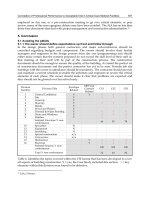
occur with low level lighting on access ways (Figure 3.9.15) or high
level lights in areas of lifting operations. Similarly, viewing is
interfered with if the emissions from a source of light shine directly on
the eye.
(b) Areas of sharp contrast since the eye reacts to the bright areas with the
result that the darker areas will either not be seen or be seen only with
difficulty by straining the eyes (Figure 3.9.16). Deep shadows and
fluctuating levels of light have the same effect.
(c) Reflections of a light source on the object being viewed whether
paper, metal, desk top or monitor screens.
(d) Flicker, which is a cyclic variation of light intensity that is more
noticeable at frequencies below 50Hz. It is particularly noticeable at
the edge of the visual field and can be distracting, cause fatigue and,
in some cases, epileptic seizures.
636 Safety at Work
Figure 3.9.15 Disability glare from a light fitting (Courtesy The Stationery Office)
Figure 3.9.16 Sharp contrast between exterior light and interior shadow (Courtesy
the Stationery Office)
Applied ergonomics 637
(e) Stroboscopic effect occurs when the flicker from fluorescent lamps
coincides with the speed of rotating objects making them appear
stationary. This can be avoided by utilising twin tube fittings wired
90° out of phase.
3.9.3.6.1 Types of illuminaires
Sources of artificial light split broadly into two types:
(i) point sources such as the tungsten filament lamp where a glass
envelope containing either a vacuum or a filling of halogen, mercury
or sodium vapour at pressure. Since the filament is heated to white
heat to provide the illumination the surrounding glass envelope can
get hot. Adequate arrangements for cooling are needed and the lamp
should not be located near flammable materials. Because this type of
illuminaire is a point source of light it is important that it does not:
᭹ create areas of bright light and deep shadows,
᭹ reflect on work surfaces and
᭹ mask information on VDU monitors.
The gas used to fill the bulb – mercury, sodium or halogen – creates
a colour bias in the light emitted. This must be allowed for in
processes where colour recognition is important, such as electrical
wiring, paint colour matching, etc.
(ii) fluorescent strip light fittings in which the light emanates from the
fluorescent coating on the inside of the tube. Although giving a
much more even spread of light than tungsten lamps they can still
cause reflections on surfaces. This effect can be reduced to a
minimum by the use of diffusers and louvre fittings. Problems that
are met with this type of illuminaire include:
᭹ flicker and
᭹ stroboscopic effect.
The positioning of illuminaires is important to ensure they do not create
interference with viewing. Where interference does occur, the object being
viewed should be moved or the illuminaire repositioned. Advice on the
type and positioning of luminaires is given in a guidance note
5
.
3.9.3.7 Ventilation
The presence of contaminants in the atmosphere is a potential source of
distraction and annoyance. They may be there as a result of fumes or dust
leaking from the process or of someone’s personal habits such as
smoking. With contaminants there is also an associated potential health
risk (from hazardous fumes and dusts, tobacco smoke, etc.). Legislation
7
requires the supply of a sufficient quantity of fresh or purified air. It does not
specify quantities but guidance
5
suggests a minimum of 5–8 l/s per
occupant (18–29 m
3
/h). However, this does not allow for the effects of the
production process nor the type of work so these quantities may need to
be increased. Fresh air is that drawn from outside but care needs to be
taken to ensure the intake point is clear of exhaust outlets or other sources
10kg
F
u
ll h
e
i
g
h
t
20kg
Shoulder height
25kg
Elbow height
20kg
Knuckle height
Knee height
10kg
5kg
10kg
15kg
10kg
5kg
638 Safety at Work
that might contaminate the air or be hazardous or evil smelling. Purified
air refers to recirculated air that has been ‘conditioned’ but the Code of
Practice
5
recommends that some fresh air should be added to it although
again no quantity is specified.
In many situations, an adequate supply of fresh air can be obtained from
an open window but in the larger open plan offices and workshops some
form of forced air ventilation may be required. The outlets from ventilation
systems should be arranged so that they do not play on an individual since
this can be a source of annoyance and also interfere with sweat rates to
become a health hazard. Outlet velocities and directions of flow should
ensure that the air velocity at any one workstation is not so high as to be
unpleasant or uncomfortable. In general, the more active the work an
airflow as high as 0.5 m/s can be tolerated. However, for sedentary work
the flow should be less than 0.1 m/s while in jobs requiring deep
concentration even that level of air movement can be distracting.
3.9.4 Manual handling
Ideally, if objects have to be moved it should be done mechanically. Where
this is neither technically feasible nor economically viable manual
handling will have to be employed. Manual handling is a known and well
documented source of occupational injury and in spite of publicity and
training accident attributed to manual handling remains the highest cause
of absences. Legislation
8
sets out the actions to be taken to reduce the
hazards with advice on ways to achieve them given in a Code of Practice
9
.
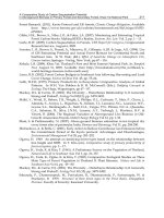
The ability to handle loads varies with the position of the load with respect
to the body and Figure 3.9.17 indicates a suggested range of maximum
Figure 3.9.17 Suggested maximum loads at various distances from the body
Applied ergonomics 639
weights that can be lifted and carried. The values given are typical and will
need to be adjusted to suit the physique and ability of the operator. It is
important to remember that it is not only what is picked up but how.
For manual handling, work should be arranged so that:
᭹ the load to be lifted is the smallest technically feasible and economi-
cally viable;
᭹ loads that cannot be broken down to safe weights are handled by
mechanical means such as sack barrow, special purpose handling
equipment, lift trucks, etc.;
᭹ the level from which the load is lifted should be as high as possible up
to waist level;
᭹ ideal height for picking up a load is waist level;
᭹ if necessary an intermediate resting platform is provided;
᭹ close body approach is possible to the delivery platform to prevent the
need to lean with the load;
᭹ the final delivery level is not above shoulder height;
᭹ for placing loads at higher than shoulder level a lift truck or suitable
step ladder is used.
Where loads have to be carried manually, the floor surface should be
level, smooth and in good condition.
Where manual handling has to be carried out from the sitting position,
the ability to lift may need to be reduced to as little as 20% of the
equivalent load when standing.
3.9.5 Repetitive actions
Actions that involve putting repeated loads on particular muscles,
especially on the arms and the wrist, can cause a number of muscular
conditions variously referred to as repetitive strain injury (RSI), tenosyno-
vitis, carpal tunnel syndrome, work-related upper limb disorder, etc.
Symptoms exhibited include soreness in the muscles that initially
disappears when ceasing work but rapidly returns when work is
recommenced. If the same work is continued, the condition can become
very painful and have long lasting effects.
On jobs where this condition is a known or suspected risk arrange-
ments should be made to:
᭹ eliminate the type of work that causes the condition and replace it by
alternative work methods;
᭹ restrict the time engaged on the suspect activity;
᭹ rotate jobs during the shift so that operators carry out a number of
different functions using different muscles;
᭹ ensure tools and equipment used on suspect operations are, and are
maintained, in good condition and do not require excessive force for
their proper use;
᭹ build into the work programme adequate rest periods;
᭹ instruct supervisors and operators in the symptoms and the action to
be taken if they occur, i.e. move to alternative work and seek medical
advice.
640 Safety at Work
3.9.6 Plant design
Layout of plant should ensure that any movements the operators need to
make are direct, free and unimpeded by other parts or equipment.
Operator work areas should be clear, clean, well lit with a good floor
surface. If the work platform is at a raised level, it should have a safety
rail and be provided with access steps if the height warrants. The treads
of steps should be wide enough to accommodate the full length of a
normal shoe. Steps at an angle greater than 45° should be avoided, but if
space limitations dictate steeper steps, proper permanent ladders with
hand rails should be provided. Any step up (or down) should not be
greater than 25 cms (10 ins). Steps higher than this can greatly increase the
strain on the knee and hip muscles with consequent increased fatigue.
Adequate space should be left around each machine to permit free and
easy movement for operating it and to allow for maintenance activities.
Walkways should be identified by suitable lining and not allowed to be
used for storage purposes. Services, such as air, water, electrical power,
necessary for the work being carried out should be conveniently situated
for the operators’ use. Machines in sequential operations should be
positioned to require the minimum amount of handling of product.
Wherever possible that handling should be automated or by mechanical
means.
The emission of noise and fumes by machinery which can affect the
operator and those on adjacent machines should be reduced to a
minimum.
3.9.7 Controls and indicators
Controls and instruments are the main interface between the operator
and the machine or plant. In the design and layout of them:
᭹ The movement of all controls must be consistent with the natural
movement of the limb operating it.
᭹ Movement of a control in a clockwise direction, to the right or towards
the operator should cause an increase in the machine function – the
exception to this is a tap or valve where clockwise movement results in
a decrease in output, i.e. the valve is shut.
᭹ Coarse adjustment and adjustments that require some force should
utilise the full arm, leg or hand movement.
᭹ Where foot pedals are used, if actuation is by movement of the whole
leg the pedals should be arranged so they can be operated by either
foot. If movement of the foot only is required it should be by pivoting
on the heel. In both cases the arrangement should ensure that the
operator is not required to stand on one leg for long periods.
᭹ Quick, precise or fine adjustments that require little physical effort
should be by the fingers.
᭹ Hand operated controls should be located at a height between waist
and shoulder level and be in clear view.
Applied ergonomics 641
᭹ Controls that have to be actuated frequently should be positioned
adjacent to or within easy reach of the operator’s hands. Other controls
should be within easy arms reach.
᭹ Adjacent hand or finger operated controls such as push buttons, toggle
switches and rotating knobs should be spaced at least 25 mm (1 in)
apart to prevent inadvertent operation.
᭹ In the layout and shape of control buttons:
᭹ start buttons should be recessed into the control panel, shrouded, or
gated to prevent inadvertent operation;
᭹ stop buttons should be positioned adjacent to the start control, stand
proud above the panel surface and be red in colour;
᭹ emergency stop buttons should be red, of the mushroom headed
type and lock in the open circuit condition when actuated.
᭹ The function of all control actuators should be clearly indicated either
by words or symbols.
᭹ Where the condition of the control is important and may need to be
known without looking at it, a datum mark such as a small pin or
notch should be made in the mounting panel and a matching pin or
notch made in the control handle. The two should line up at either
neutral or normal operating position so any deviation from it can easily
be sensed.
᭹ Control handles for separate operations should have a unique tactile
identity
10
.
᭹ Instruments that are important should be in clear view of the operator,
ideally at eye level or within 20° of the normal eye line but must not
interfere with the operator’s view of the machine or plant.
᭹ The movement of the condition indicator of an instrument should be
consistent with the change in condition, i.e. increase in the condition
shows as a clockwise movement or, in linear gauges, to the right or
upwards.
᭹ Instruments that measure associated parameters should be positioned
together and arranged so that the pointers or condition indicators all
lie in the same orientation for normal operation allowing any deviant
reading to be seen easily.
᭹ Where controls have to be actuated over periods of time with little
body movement, seating should be provided for the operator and the
positioning of the controls and instruments arranged accordingly.
Controls that are operated by the feet fall into two categories, those in
which the whole leg is moved giving only a very coarse degree of control
and those using the foot only, when a fine degree of control can be
achieved. In the former case, movement of the foot is from the hip
allowing only a basic ON/OFF type of control without any intermediate
positioning, such are used for the initiation of a press stroke or the foot
pedals of an organ.
Where a fine degree of control over the operating range is necessary
this can be achieved by pivoting the heel of the foot on the floor or
suitable rest. An even finer degree of control, such as the accelerator pedal
in a car, can be achieved by providing a support at the outer side of the
foot about which the foot can pivot. If a foot control is operated from a
642 Safety at Work
standing position, the arrangement should ensure that part of the body
weight can be taken by the operating foot, or if this is not possible, the
control should allow operation by alternate feet to prevent the excessive
strain imposed when one leg takes the full body weight.
3.9.8 Noise and vibrations
In all walks of life sound is a necessity, for communication, for warning
and leisure enjoyment (music and the theatre). Unfortunately there are
differing views about what sound is useful and what is an adequate
amount of sound. Any unwanted sound is regarded as noise and as such
should be eliminated or reduced to the lowest level possible. In general
sound that interferes with people’s enjoyment of their private lives and
pursuits becomes a nuisance and has been legislated against
11
. But excess
sound can also interfere with concentration at work and become a
potential hazard as well as reducing the operating performance of those
subject to it. Examples of typical noise levels are shown in Figure 3.5.2.
Noise in an area is likely to be a hazard if it is necessary, when standing
1 metre apart, to have to shout to carry on a conversation. Where there
appears to be a noise problem, sound level readings should be taken to
establish the extent of the problem.
The presence of noise has long been recognised as one of the factors
that reduces the quality of working life. While the human brain can ‘tune
out’ consistent and/or irrelevant noises it can only do this up to a point.
As noise levels rise so they become more insistent and invasive. Similarly
unexpected changes in even quite low levels of noise can stimulate a
subconscious response and, in some cases, break completely the current
train of thought. The problems of noise from machinery and advice on the
measures to combat it are well documented in HSE publications
12, 13
and
it is not proposed to iterate them here.
Vibrations on the other hand, where there is a finite movement of the
plant, equipment or a pulsing of the air, are much more invasive and can
interfere with certain body organs ultimately causing ill health.
Measures that can be taken to reduce the distracting effects of noise
include:
᭹ elimination of sources of noise;
᭹ if that is not possible then:
᭹ enclose the source of noise in a sound proof room but ensure
adequate cooling and ventilation is provided;
᭹ provide sound havens or soundproof operating rooms ensuring
there is adequate ventilation;
᭹ use sound absorbing screens and barriers;
᭹ separate work areas from noise sources;
᭹ position potential noise sources away from work areas – the
frequency hum from a transformer can be very invasive;
᭹ directing the outlet ducts from ventilating systems, dust extraction
systems, etc. away from affected areas. This can include private house
bedrooms where fan exhausts can become a nuisance and subject to
abatement orders;
Applied ergonomics 643
᭹ in offices, replacing noisy matrix and daisywheel printers by inkjet or
laser printers;
᭹ installing floor covering that deadens the sound of footsteps partic-
ularly the clacking of heels on a hard floor;
᭹ ban the use of personal radios in the workplace – they can interfere
with the reception of warning signals;
᭹ in open plan offices, the segregation of those with penetrating
telephone voices;
᭹ arrange for operations that generate noise, such as use of pneumatic
drills, etc., to be carried out in ‘non-working’ hours. This includes work
on part of the structure of reinforced concrete framed buildings since
noise travels through the concrete;
᭹ as a last resort, provide suitable personal protective equipment.
Mechanical vibrations generated by the movement of parts of the plant
and machinery can travel through the machine and be transmitted to the
building and those working in it. Air vibrations occur as a pulsing of the
air and can be generated at the outlet of fans and blowers and from the
exhaust of slow running engines. Both mechanical and air vibrations can
be a health hazard since they can induce sympathetic vibrations in certain
human organs resulting in damage to that organ.
The transmission of mechanical vibrations can be reduced by:
᭹ mounting the equipment on anti-vibration mounts;
᭹ providing flexible connections between the vibrating plant and other
equipment.
Air vibrations can be reduced by:
᭹ changing the speed of the fan or blower;
᭹ installing diffusers;
᭹ changing the flow resistance of the air circuit;
᭹ ensuring the intake to the fan is not obstructed.
3.9.9 Stress
Stress has many causes including an inability to do what ought to be done
or failure to meet the targets set. The cause may be within the individual
or it may be imposed from outside. Internally caused stress can only be
resolved by the individual himself but imposed stress causes can be
reduced or eliminated by following ergonomic principles. The build up of
stress in an individual will make him less efficient in his work and may
even make him a safety hazard. To optimise an individual’s performance
the stress suffered should be reduced to a minimum.
Typical stress situations, with possible ways to resolve them, include:
᭹ working at a machine led rate which is either faster or slower than the
individual’s natural work rate. Wherever possible suitable adjustments
should be made to the machine speed;
644 Safety at Work
᭹ being required to undertake work which is either well below or well
above his inherent ability. This may require a re-assessment of the operator
and moving to other more appropriate work;
᭹ being given inadequate or excessively complex instructions about his
job. Instructions should be realistic and comprehensive and in terms and
language that the operator can understand;
᭹ being prevented from working at his own natural rate. Some means
should be provided to adjust the demanded rate of work;
᭹ having to do a job in a less efficient manner than he knows it can be
done. Listen to the operator’s suggestions and act on them or explain why
not;
᭹ being uncertain of his position in the organisation and not knowing
who his bosses are. Provide training in the role and position within the
company covering areas of responsibility, extent of authority, subordinates
and superiors, etc.;
᭹ having to wait for materials or data. Improve planning and expediting;
᭹ being unable to understand and follow work methods. Further training
and the provision of back-up information;
᭹ working in software in which he has not been properly trained and
without back-up. Ensure adequate training and provide competent back-up
to resolve queries;
᭹ at loggerheads with his supervisor. A personal matter to be resolved by the
individuals or by separating them;
᭹ being pressurised by his peer group;
᭹ under a threat of redundancy without having any details. Ensure kept
informed of the latest position;
᭹ family affairs;
᭹ frustration with lack of progress on agreed action affecting his work
and working conditions. Initiate suitable action or explain why it has not
been possible;
᭹ lack of recognition for ideas put forward. Improve human relations in the
company;
᭹ irritating noises. Investigate and eliminate;
᭹ boredom from repetitive uninteresting work. Re-assess ability and move
to more demanding work.
3.9.10 Display screen equipment (DSE)
The ergonomic aspects of the use of DSEs has been well documented in
the HSE’s guidance publication
14
particularly those aspects concerned
with the physical comfort of the users and operators such as:
᭹ chair with adjustments for seat height and back rest;
᭹ suitable foot rest;
᭹ adequate leg room below work table;
᭹ adjustable screen both rotating and tilting;
᭹ document holder to reduce amount of eye movement;
᭹ limit on time of continuous operation;
᭹ training in the use of the software with back-up immediately available
in case of queries;
Applied ergonomics 645
᭹ screen should have adjustments to ensure stable picture, enable change
of polarity of characters and control over contrast;
᭹ work surface to be large enough to accommodate keyboard, all
papers/documents and any peripherals such as the mouse, printers,
disc, imager, etc.
DSEs can make the atmosphere very dry and cause discomfort. Sources of
moisture, such as house plants, should be installed to improve the
humidity.
3.9.11 Signs and signals
Signs and signals are a vital means of passing information where verbal
contact is not possible or reasonable. The signs, generally, in the form of
posters, warnings, etc., are passive while signals, usually by hand or light,
are dynamic. It is important that those who need to read signs know their
correct meaning. In the passing of operational information by hand
signals, such as in the use of cranes, it is important that both the signaller
and the receiver (crane driver, etc.) use the same codes
15
and that both are
fully conversant with the full range of hand signals. Familiar hand signs
have different meanings in different countries and care must be exercised
when selecting hand signals to ensure they are not in common usage in
workers’ mother countries where they may have a totally different, and
sometimes insulting, meaning.
With the number of migrating workers travelling to work in countries
foreign to them, meeting obligations to provide information presents
difficulties of language. This can largely be overcome by the use of
pictograms. Standards
16
, incorporating the requirements of a directive,
specify a range of pictogram safety signs with the aim of their being
understood regardless of the language of the viewer. The standard signs
are intended to be stand-alone but text may be added where necessary to
provide additional information.
The positioning of signs is important. They must be placed where they
will be clearly visible by those at whom they are aimed. Emergency signs,
such as fire exits, fire points, etc., should be clearly visible from all places
to which employees, visitors and others may have recourse as a normal
part of their activities. The height at which signs are located should be
considered. A fire emergency exit sign at chest height is of no use if, in an
emergency, the rush of people from the area completely cover it.
Emergency safety signs should be positioned above head height so they
are clearly visible from all parts of the area they serve. Conversely, signs
placed at high levels are often overlooked because the general trend is to
look downwards rather than upwards. Signs should be mounted within
a sight line of 20° above horizontal when viewed from all the areas
served.
Care must be exercised when selecting audible signals to ensure, first,
that they do not add to the general noise to the extent of raising it above
the accepted safe levels. Second, they must be clearly distinguishable
from all other audible signals and from other normal sounds in the area.
646 Safety at Work
Where audible warnings are used, such as fire alarms, reversing vehicles,
etc., the signal must be audible to all those likely to be in a position of risk
from the danger warned against. Audible warnings should not be used
with such frequency that they become a part of the general background
noise, also that their use does not become an irritant to others working
nearby. Where audible warnings are employed all those in areas covered
by the warning should be familiar with the sound and with the action to
be taken.
Public places such as cinemas, theatres, stores, supermarkets, etc.,
present a particular problem in an emergency. Staff should be trained in
advising the public what to do should an alarm be sounded. The use of
broadcast verbal warnings or safety instructions should be avoided since
the message may be inaudible in some areas, can be misunderstood and
give rise to confusion.
3.9.12 Coda
The application of ergonomic principles to work activities can make life
safer and more pleasant for employees. Many of the ergonomic
techniques are being incorporated into regulatory requirements and into
standards but there are still many techniques that the employer can adopt
that will further improve not only the safety and quality of working life
but productivity.
References
1. British Standards Institution, BS EN 614–1 Safety of Machinery – Ergonomic design
principles – Part 1: Terminology and general principles, BSI, London (2000)
2. Kroemer, K.H.E. and Grandjean, E., Fitting the Task to the Human, 5th edn, Taylor &
Francis, London (1999)
3. British Standards Institution, BS IEC 60529 Degrees of protection provided by enclosures (IP
code), BSI, London (1991)
4. British Standards Institution, BS IEC 60204 Safety of machinery – Electrical equipment of
machines – Part 1: General requirements, Clause 10.2, Push buttons, BSI, London (1997)
5. Health and Safety Executive, Legal series publication L24 Workplace health, safety and
welfare. Workplace (Health, Safety and Welfare) Regulations 1992, Approved Code of Practice
and Guidance. HSE Books, Sudbury (1992)
See also health and safety guidance series publication HSG 202 General ventilation in the
workplace, HSE Books, Sudbury (2000)
6. Health and Safety Executive, Health and safety guidance series publication HSG 38
Lighting at work, HSE Books, Sudbury (1998)
7. Workplace (Health, Safety and Welfare) Regulations 1992, Regulation 6, Ventilation, The
Stationery Office, London (1992)
8. Manual Handling Operations Regulations 1992, The Stationery Office, London (1992)
9. Health and Safety Executive, Legal series publication L23 Manual Handling, Manual
Handling Operations Regulations 1992, Guidance on the Regulations, HSE Books, Sudbury
(1992)
See also Health and safety guidance series publication HSG 115, Manual handling
solutions you can handle, HSE Books, Sudbury (1994)
10. British Standards Institution, BS IEC 61310, Safety of machinery – Indication, marking and
actuation – Part 1: Requirements for visual, auditory and tactile signals, BSI, London
(1995)
Applied ergonomics 647
11. Environmental Protection Act 1990, The Stationery Office, London (1990)
12. Health and Safety Executive. Legal series publication L108 Guidance on the Noise at Work
Regulations 1989, HSE Books, Sudbury (1998)
13. Health and Safety Executive, Health and safety guidance series publication L138 Sound
solutions, techniques to reduce noise at work, HSE Books, Sudbury (1995)
14. Health and Safety Executive, Legal series publication L26 Display screen equipment work
– Health and Safety (Display Screen Equipment) Regulations 1992, Guidance on the
Regulations, HSE Books, Sudbury (1992)
15. British Standards Institution, BS 7121 Code of Practice for the safe use of cranes, BSI,
London
16. British Standards Institution, BS 5378 Safety signs and colours and BS 5499 Fire safety signs,
notices and graphic symbols, BSI, London
Suggested reading
Kroemer, K.H.E. and Grandjean, E., Fitting the Task to the Human, 5th edn, Taylor & Francis,
London (1999)
Bridger, R.S., Introduction to Ergonomics, McGraw Hill, Singapore (1995)
Pheasant, S., Ergonomics, Work and Health, Macmillan Press, London (1991)
Helander, M., A Guide to the Ergonomics of Manufacturing, Taylor & Francis, London (1995)
Chartered Institution of Building Services Engineers, Code for Interior Lighting, CIBSE,
London (1994)
McKeown, C. and Twiss, M., Workplace Ergonomics: a Practical Guide, IOSH Publishing
Services Ltd., Leicester (2001)
PART IV
Workplace safety
Chapter 4.1 Science in engineering safety (J. R. Ridley) 651
Chapter 4.2 Fire precautions (Ray Chalklen) 671
Chapter 4.3 Safe use of machinery (J. R. Ridley) 727
Chapter 4.4 Electricity (E. G. Hooper and revised by
Chris Buck) 769
Chapter 4.5 Statutory examination of plant and equipment
(J. McMullen and updated by J. E. Caddick) 793
Chapter 4.6 Safety on construction sites (R. Hudson) 819
Chapter 4.7 Managing chemicals safely (John Adamson) 850
Much of the work undertaken by safety advisers requires an under-
standing of technical industrial processes. Even in a single factory unit
the safety adviser may be called upon to advise on avoiding the hazards
from a chemical reaction, guarding particular types of machinery, the
standards of safe working to be expected of a building contractor, the
precautions to be taken to prevent fire and the fire fighting equipment
that should be provided, etc.
To carry out his duties effectively, the safety adviser should have an
understanding of basic physics and chemistry and of the current safety
techniques for reducing the risks associated with the more commonly met
industrial processes. This Part considers some of these processes and the
basic sciences from which they stem.
Chapter 4.1
Science in engineering safety
J. R. Ridley
4.1.1 Introduction
In the construction of machines, plant and products, materials are
selected because they have particular physical and chemical properties.
Wood, metals, concrete, plastics and other substances all have their uses
but there are limitations as to what they can do and how long they can do
it. Properties may change with use, temperature, operating atmosphere,
contamination by surrounding chemicals and for many other reasons. It
is necessary to know the properties of the materials and how and why
they have been used so that an assessment can be made of whether likely
changes in the properties may give rise to hazards.
These properties stem from the chemical and physical characteristics of
the different materials and substances used and their behaviour under
certain conditions can determine the safety or otherwise of a process or
operation. This chapter looks at some of the characteristics and properties
of materials in common use, their application, circumstances of use and
possible causes of hazards.
4.1.2 Structure of matter
Everything that we use in our work and daily life is made up of chemical
substances, by themselves or in combination of one sort or another. Each
substance consists of elements which are the smallest part of matter that
can exist by itself. In its free state, an element comprises one or more
atoms. When atoms combine together they form molecules of the element
or, if different atoms combine, of compounds. The ratio in which atoms
combine is determined by their combining power or valency.
Atoms are made up of three particles:
᭹ protons which have a unit mass and carry a positive charge,
᭹ neutrons which have a unit mass but carry no charge, and
᭹ electrons which have negligible mass (i.e. 1/2000 proton) but carry a
negative charge.
651
652 Safety at Work
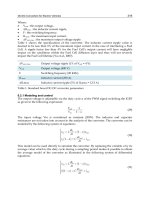
The core or nucleus of the atom consists of protons and neutrons with
electrons travelling in orbits around the nucleus (Figure 4.1.1). Elements
normally have no overall charge since the number of protons is matched
by an equal number of electrons. However, it is possible to upset this
balance by removing either a proton or an electron resulting in the atom
carrying a charge when it is said to be ionised.
In chemistry, atoms are given ‘atomic numbers’ which equal the
number of protons or electrons in the atom. They are also given ‘mass
numbers’ which equal the sum of the number of protons plus neutrons.
The mass number is always equal to or greater than 2 ϫ the atomic
number except in the case of hydrogen. Some elements can occur in
conditions where they have the same atomic number, and hence the
same name, but different mass numbers; they are then known as
isotopes and are generally referred to as nuclides. Very large heavy
atoms, such as uranium, can be unstable and easily break down to
produce smaller atoms with the production of particles or energy. These
atoms are radioactive and provide the source of energy in nuclear
reactors.
Approximately 100 different atoms have been identified and each has
been given a name and a coded symbol which usually is the first one or
two letters of its name: carbon – C, lithium – Li, titanium – Ti, etc.
Exceptions in this coding system arise because when it was evolved in the
early 1800s some chemicals were still known by their Latin names, such
as copper (cuprum – Cu) and tin (stannum – Sn).
When atoms join together their molecular formulae are written as
groups of atomic symbols to indicate the number of those atoms present
to form a stable molecule.
Molecular formulae
Br
2
bromine
O
2
oxygen
H
2
O water
NaOH sodium hydroxide (caustic soda)
Figure 4.1.1 Atomic structures
Science in engineering safety 653
CBrF
3
bromotrifluoromethane (BTM or Halon 1301)
HCHO formaldehyde
C
2
H
5
NO
3
ethyl nitrate
Each compound has its own properties which may be vastly different
from those of the constituent atoms. Atoms within a molecule cannot be
separated unless the compound undergoes a chemical reaction.
A chemical reaction occurs when the atoms in molecules rearrange
either by decomposing into smaller molecules or by joining with other
atoms to form different molecules; in both cases the atoms reorganise
themselves to form different structures. Endothermic reactions require
the input of heat to make them happen whereas exothermic reactions
occur with the evolution of heat.
2Na + 2H
2
O = 2NaOH + H
2
+ heat
2H
2
+ O
2
=2H
2
O + heat
These chemical equations show in chemical shorthand, using the
chemical codes, the rearrangement of atoms which occurs in these
reactions, a balance of the number of atoms being maintained during the
reaction. The molecular mass of molecules can be obtained by adding
together the mass numbers of the constituent atoms.
Compounds which contain atoms of elements other than carbon, but
including carbon dioxide (CO
2
), carbon monoxide (CO) and the
carbonates (e.g. calcium carbonate CaCO
3
) are called inorganic chemicals.
All other compounds which contain carbon atoms are known as organic
chemicals.
Carbon is an unusual element; not only is it able to form simple
compounds where one or two carbon atoms are joined to atoms of other
elements, but carbon atoms can link together to form chains or rings of
atoms. Almost all other atoms can be joined into these chains and rings to
create millions of different organic compounds, from the comparatively
simple ones consisting of one carbon with one other type of atom to the
highly complex molecules with hundreds of linked carbon atoms joined
with other different atoms. Organic chemicals include most of the
solvents, plastics, drugs, explosives, pesticides and many other industrial
chemical substances.
4.1.3 Properties of chemicals
Properties of chemicals are to a large extent determined by how the atoms
are bonded.
4.1.3.1 Metals
Metals are different in structure from both types of compounds described
below, existing in the solid state as an ordered array of atoms held
together by their electrons which circulate freely between them. Applica-
654 Safety at Work
tion of an electric potential across a metal allows the electrons to undergo
a directional flow between the atoms making metals good electrical
conductors. Table 4.1.1 lists the properties of some typical metals and
other elements.
4.1.3.2 Inorganic compounds
In some compounds one or more of the bonds joining the atoms are the
result of an unequal sharing of electrons between the two atoms and these
produce ionic compounds which are crystalline solids, usually with a
high melting point. They are often soluble in water giving a solution
which conducts electricity.
Many other compounds have bonds based on an equal sharing of
electrons and so do not ionise. These compounds can be solids having
low melting points, or liquids or gases. Usually they are not soluble in
water unless they react with it. There are also many more compounds
with types of bond intermediate between the two described and which
exhibit properties that relate to both types. Table 4.1.2 lists some of the
properties of a selection of inorganic compounds.
With the exception of sulphur, stannic chloride and potassium chloride,
all the elements and compounds listed in Tables 4.1.1 and 4.1.2 present
hazards to health.
Table 4.1.1 Properties of typical elements
Element Symbol Properties
Reactive metals
Aluminium Al m.p. 660°C, good conductor, surface oxide
formation resists attack by air or water
Barium Ba m.p. 850°C, soft, spontaneously flammable in air,
reacts with water
Lithium Li m.p. 186°C, soft, burns vigorously in air, reacts
with water
Less reactive metals
Cobalt Co m.p. 1490°C, hard, not attacked by air or water
Iron Fe m.p. 1525°C, burns in oxygen, reacts slowly with
water
Mercury Hg liquid, slowly attacked by oxygen, no reaction with
water
Silver Ag m.p. 961°C, ductile, not attacked by oxygen or
water
Non-metals
Bromine Br dark red liquid, b.p. 59°C, very reactive, not
flammable
Phosphorus P red form, m.p. 600°C or white form, m.p. 43°C,
burns readily to P
2
O
5
, insoluble in water
Sulphur S yellow or white, m.p. 115°C, burns to SO
2
,
insoluble in water
Science in engineering safety 655
4.1.3.3 Organic compounds
As most organic compounds contain a relatively large percentage of
carbon and hydrogen atoms they are flammable and many are toxic. All
living matter is constructed of complex interdependent organic chemicals
and it is because organic compounds interfere with the normal
functioning of living matter that they constitute fundamental health and
hygiene hazards.
Although there are very many organic compounds they can be
grouped into a small number of classes according to their reactive
properties. These broad groups are listed in Table 4.1.3 which gives
examples of compounds in each group.
4.1.3.4 Acids and bases
Acids are compounds which dissolve in water to give hydrated hydrogen
ions:
HCl + H
2
O=H
3
O
+
+ Cl
–
H
2
SO
4
+ H
2
O=H
3
O
+
+ HSO
–
4
Strong acids completely dissociate into ions in solution; weak acids only
partially dissociate. A concentrated acid is one which is not diluted with
water, and the terms strong and concentrated should not be confused.
Acids are corrosive in that they react with both metals and with body
proteins. Acids are dangerous not just because of their acidity but they
can be oxidising agents (HNO
3
, HClO
4
), violently reactive with water
Table 4.1.2 Properties of a selection of inorganic compounds
Compound Formula Properties
Ammonia NH
3
gas, b.p. –33°C, dissolves readily in water giving a
basic solution
Carbon monoxide CO gas, b.p. –190°C, odourless, almost insoluble in
water
Hydrogen chloride HCl gas, b.p. –85°C, dissolves readily in water giving
hydrochloric acid
Hydrogen sulphide H
2
S gas, b.p. –61°C, strong odour, burns in air
Hydrogen peroxide H
2
O
2
liquid, decomposes violently on heating, powerful
oxidising agent
Stannic chloride SnCl
4
liquid, b.p. 114°C, fumes, reacts rapidly with water
Sulphuric acid H
2
SO
4
liquid, decomposes at 290°C giving SO
3
, strong
acid, reacts violently with water
Aluminium silicate Al
2
Si
2
O
7
solid, infusible, unreactive, clay silicate
Phosphoric acid H
3
PO
4
solid, m.p. 39°C or syrupy liquid, strong acid
Potassium chloride KCl solid, m.p. 770°C, very soluble in water, unreactive
Sodium hydroxide NaOH solid, m.p. 318°C, deliquescent, strong alkali
656 Safety at Work
(H
2
SO
4
) and many are toxic. Phenol (C
6
H
5
OH) is one of the most
dangerous acidic organic compounds.
Bases are of two types, solid alkalis such as metal hydroxides which
dissolve in water to give hydroxide ions, and gases and liquids such as
ammonia and the amines, which liberate hydroxide ions on reaction with
water:
NaOH + H
2
O=Na
+
+ OH
–
+ H
2
O
NH
3
+ H
2
O=NH
+
4
+ OH
–
Some of the bases are toxic, many react exothermally with water and all
are highly corrosive or caustic towards proteins. Alkalis spilled on the
skin penetrate much more rapidly than acids and should be leached out
with copious water and not sealed in by attempting neutralisation.
The reaction between an acid and a base is a vigorous, exothermic
neutralisation forming a salt. The strength of acids and bases can be
measured in terms of hydrogen ion concentration by the use of either
meters or test papers, and it is expressed as a pH value on a scale from 0
(acid) to 14 (base). Pure water has a neutral pH of 7.
Table 4.1.3 Examples of the main groups of organic compounds
Group Example Formula Use
Aliphatic Methane CH
4
natural gas
hydrocarbons Butane C
4
H
10
petroleum gas
Aromatic Benzene C
6
H
6
toxic solvent
hydrocarbons Toluene C
6
H
5
CH
3
solvent
Halocarbons Bromomethane CH
3
Br fumigant
Trichloroethane CH
3
CCl
3
solvent
Alcohols Ethanol C
2
H
5
OH ‘alcohol’
Glycerol C
3
H
5
(OH)
3
glycerine
Carbonyl
compounds
Formaldehyde
(methanal)
HCHO fumigant
Benzaldehyde C
6
H
5
CHO manfacturing
Acetone CH
3
COCH
3
solvent
Ethers Ethyl ether C
2
H
5
OC
2
H
5
anaesthetic
Dioxan C
4
H
8
O
2
solvent
Amines Methylamine CH
3
NH
2
manufacturing
Aniline C
6
H
5
NH
2
manufacturing
Acids Ethanoic acid CH
3
CO
2
H acetic acid
Phthalic acid C
6
H
4
(CO
2
H)
2
manufacturing
Esters Ethyl acetate CH
3
CO
2
C
2
H
3
solvent
Amides Acetamide CH
3
CONH
2
manufacturing
Urea CO(NH
2
)
2
by-product
Science in engineering safety 657
4.1.3.5 Air and water
Air and water deserve to be considered separately since they are ever
present and are necessary for the operation of many processes and
responsible for the degradation of many materials.
Air is a physical mixture of gases containing approximately 78%
nitrogen, 21% oxygen and 1% argon. These proportions do not vary
greatly anywhere on the earth but there can be additional gases as a result
of the local environment: carbon dioxide and pollutants near industrial
towns, sulphur fumes near volcanoes, water vapour and salts near the sea
etc.
Air can be liquefied and its constituent gases distilled off; liquid
nitrogen (b.p. –196°C) has many uses as an inert coolant, liquid oxygen
(b.p. –183°C) is used industrially in gas-burning equipment and in
hospitals, and argon (b.p. –185.7°C) is used as an inert gas in certain
welding processes. Liquid oxygen is highly hazardous as all combustible
materials will burn with extreme intensity or even explode in its presence.
Combustion is a simple exothermic reaction in which the air provides the
oxygen needed for oxidation. If the concentration of oxygen is increased
the reaction will accelerate. This effect was experienced in the fire on
HMS Glasgow
1
.
Water is a compound of hydrogen and oxygen that will not oxidise
further and is the most common fire extinguishant. However, caution
must be exercised in its use on chemical fires since a number of oxides
and metals react energetically with it, in some cases forming hazardous
daughter products and in others producing heat and hydrogen which
further exacerbate the fire.
4.1.4 Physical properties
All matter, whether solid, liquid or gas, exhibits properties that follow
patterns that have been determined experimentally and are well
established and proven. This section looks at some of the factors that
influence the state of matter in its various forms.
4.1.4.1 Temperature
Temperature is a measure of the hotness of matter determined in relation
to fixed hotness points of melting ice and boiling water. Two scales are
universally accepted, the Celsius (or Centigrade) scale which is based on
a scale of 100 divisions and the Fahrenheit scale of 180 divisions between
these two hotness points. Because Fahrenheit had recorded temperatures
lower than that of melting ice he gave that hotness point a value of 32
degrees. Converting from one scale to the other:
(°F – 32) ϫ 5/9 = °C
(°C ϫ 9/5) + 32 = °F
658 Safety at Work
Man has long been intrigued by the theory of an absolute minimum
temperature. This has never been reached but has been determined as
being –273°C. The Kelvin or absolute temperature scale uses this as its
zero, O K; thus on the absolute scale ice melts at +273 K.
Devices for measuring temperature include the common mercury in
glass thermometer, thermocouples, electrical resistance and optical
techniques.
4.1.4.2 Pressure
Pressure is the measure of force exerted by a fluid (i.e. air, water, oil etc.)
on an area and is recorded as newtons per square metre (N/m
2
). With
solids the term stress is used instead of pressure. Datum pressure is
normally taken as that existing at the earth’s surface and is shown as zero
by pressure gauges which indicate ‘gauge pressure’ (i.e. the pressure
above atmospheric). However, at the earth’s surface the weight of the air
of the atmosphere exerts a pressure of 1 N/m
2
or 1 bar. Beyond the earth’s
atmosphere there is no pressure and this is taken as the base for the
measurement of pressure in absolute terms. Thus:
gauge pressure = absolute pressure –1 N/m
2
or absolute pressure = gauge pressure +1 N/m
2
The pressure at the top of a mercury barometer, where the force due to the
weight of the atmospheric air outside the tube is balanced by the force
exerted by the weight of the column of mercury inside, is normally taken
as zero (0 N/m
2
or absolute vacuum), although scientifically there is a
small vapour pressure from the mercury.
Pressure can be measured by means of manometers which show the
pressure in terms of the different levels of a liquid in a U-tube, by
mechanical pressure gauges which record the differential effect of
pressure forces on the inside and outside surfaces of a coiled tube or of a
diaphragm, and electronic devices which measure the change of electrical
characteristic of an element with pressure.
4.1.4.3 Volume
Volume is the space taken up by the substance. With solids which retain
their shape, their volume can be measured with comparative ease. Liquid
volume can be measured from the size of the containing vessel and the
liquid level. Gases, on the other hand, will fill any space into which they
are introduced, so to obtain a measure of their volume they must be
restrained within a sealed container.
Each type of material reacts to changes of temperature and, to a lesser
extent with solids and liquids, to changes of pressure, by increases or
decreases in their volume and this fact can be made use of, or has to be
allowed for, in many industrial processes and plant.
Science in engineering safety 659
4.1.4.4 Changes of state of matter
At ordinary temperatures, matter exists as solid, liquid or gas but many
substances change their state as temperatures change – for example, ice
melts to form water at 0°C and then changes into steam at 100°C. The
stages at which these changes of state occur are also influenced by the
pressure under which they occur.
4.1.4.4.1 Gases
In gases the binding forces between the individual molecules are small
compared with their kinetic energy so they tend to move freely in the
space in which they exist. When heated, i.e. additional kinetic energy is
given to them, they move much more rapidly and if restrained in a fixed
volume impinge more energetically on the walls of the containing vessel,
a condition that is measured as an increase in pressure. The relationship
between temperature, pressure and volume of gases is defined by the
general Gas Law:
PV
T
(initial) =
PV
T
(final)
where P = absolute pressure, V = volume and T = absolute
temperature.
Thus in a reaction vessel which has a fixed volume, if the temperature
is increased, so the pressure will increase. If the reaction is exothermic
and the temperature increase is not controlled there is a risk that the
pressure in the vessel could rise above the safe operating level with
consequent risk of vessel failure, a situation that may be met in chemical
processes that use autoclaves and reactor vessels.
This general law applies with variation when gases are compressed in
that the temperature of the gas rises. In air compressors where there is
likely to be oil present the temperature of the compressed air must be
kept below a certain level to prevent ignition of the contained oil.
Conversely, when the pressure of a gas is decreased, the temperature
drops, a condition that can be seen with bottles of LPG where a frost rime
forms and where in cold weather there is a danger of the temperature of
the gas dropping so low that the control valve freezes up.
Some gases can be compressed at normal temperature until they
become liquids (e.g. carbon dioxide, chlorine, etc.), and can conveniently
be stored in that state, while others, called permanent gases, cannot be
liquefied in this way but are stored either as compressed gases (e.g.
hydrogen, air etc.) or under pressure in an absorbent substance (e.g.
acetylene).
Air, carbon dioxide and a number of other gases which dissolve in
water become more soluble as the pressure increases or the temperature
decreases. Increase in temperature or decrease in pressure causes the
dissolved gases to come out of solution, e.g. tonic water or fizzy
lemonade. This is why hydraulic systems need venting. A similar