Seamanship Techniques 2011 E Part 13 potx
Bạn đang xem bản rút gọn của tài liệu. Xem và tải ngay bản đầy đủ của tài liệu tại đây (1.07 MB, 40 trang )
183Fire-Fighting
INTERNATIONAL SHORE CONNECTION
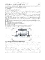
This is a fitment which is normally carried by all ships in order to
provide a common link between shore hydrants and ships’ fire mains
(Figure 7.8). It is employed either aboard the vessel itself or ashore in
conjunction with local fire brigade tenders, in the event of fire breaking
out while the vessel is in port. The shore connection is usually situated
in such a position as to be easily accessible to Fire Brigade officers, e.g
near the top of accommodation ladders, or mate’s office.
Figure 7.8 International shore connection.
114 mm
Blank is drilled for four bolts.
The hose flange has four bolts
and four slots for the shore
hose if required.
Indicator plate
305 mm
115 mm
Brass keep chain
14.5 mm
Blank
flange
SELF-CONTAINED BREATHING APPARATUS
The Siebe Gorman International Mk II, self-contained breathing apparatus
(Figure 7.9) employs two cylinders of compressed air, which the wearer
exhales direct to atmosphere. The cylinders are of a lightweight design,
so that, when fully charged, the apparatus complete with mask weighs
only 38 lb. (17 kgs). The cylinder volume is 4 litres, providing enough air
for 20 minutes when the wearer is engaged on hard work. Both cylinders
have the same capacity.
The amount of work carried out by the wearer will obviously affect
the consumption of air, and, consequently, the time that person may
continue working. The following are guidelines supplied by the
manufacturer:
Hard work rate 40 minutes (twin cylinders).
Moderate work rate 62 minutes.
At rest 83 minutes.
Pre-operational Checks (monthly)
1. Ensure that by-pass control is fully closed.
2. Open cylinder valves. The whistle, if fitted, will be momentarily
heard as pressure rises in the set. Check cylinders are fully charged.
184 Seamanship Techniques
Pressure guage tube
Warning
whistle
Pressure guage
Mask supply hose
Warning whistle adapter
Bayonet fitting
Harness
Back
plate
Auxiliary air
line adapter
C
Pressure
gauge shut off
Cylinder
valve
Emergency
by-pass
control
Cylinder
Vistarama
face mask
Demand
valve
Figure 7.9 Siebe Gorman International Mark II
compressed air breathing apparatus.
3. Any leaks in the apparatus will be audible and should be rectified by
tightening the appropriate connections, but do not overtighten.
4. Close cylinder valves and observe pressure gauge. Provided it does
not fall to zero in less than 30 seconds, the set is leak-tight.
5. Depress demand valve diaphragm to clear circuit of compressed air.
6. Close pressure gauge shut-off valve and reopen cylinder valves. The
pressure should remain at zero. Reopen first valve.
7. Gently open emergency by-pass control; air should then be heard to
escape from the demand valve. Close control.
8. Close cylinder valves. Gently depress demand valve diaphragm
and observe pressure gauge. When it falls to approximately 43 ats.
(44.5 kg/cm
2
), the whistle should sound.
Preparation for Use
1. Demist mask visor with anti-dim solution.
2. Don the apparatus and adjust harness for comfortable fit.
3. Open cylinder valves. Put on the mask and adjust to fit by pulling
the two side straps before the lower ones.
185Fire-Fighting
4. Inhale deeply two or three times to ensure that the air is flowing
freely from the demand valve and that the exhalation valve is
functioning correctly. Hold breath and make certain that the demand
valve is shutting off on exhalation or that leakage, if any, is slight.
5. Close cylinder valves and inhale until air in the apparatus is exhausted.
6. Inhale deeply. The mask should crush on to the face, indicating an
air-tight fit of both the mask and the exhale valve.
7. Reopen cylinder valves.
There are several manufacturers of breathing apparatus, and the sequence
of operations may differ slightly from that described above. Caution in
following correct procedures is advised in all cases, together with regular
practice drills in the use of this type of emergency equipment.
EXAMPLE: CARGO FIRES
LNG (Liquid natural gas)
Natural gas contains numerous component gases but by far the greater
percentage is methane (CH
4
), which represents between 60 and 95 per
cent of the total volume. This fact is important when considering the
safety aspects for fire-fighters tackling an LNG fire.
During the initial period of vaporisation of the gas, ignition may be
accompanied by a flash of varying proportions. However, because the
velocity of propagation of a flame is lower in methane than in other hydro-
carbon gases, it is unlikely that future ignition will have flash effect.
The fire-fighting plan should be well thought out in advance and a
concentrated effort made rather than ‘hit and run’ tactics, as these will
only consume the vessel’s extinguishing facilities without extinguishing
the fire. Before attempting to tackle a large fire, you should seriously
consider allowing the fire to burn itself out.
Should an attempt to extinguish the fire be made, extensive use of
‘dry powder’ should be employed from as many dispensers as can be
brought to bear. Fire-fighters should be well protected against heat
radiation and possible flash burns, and approach the fire from an upwind
direction. Power dispensers should sweep the entire area of the fire, but
direct pressure of powder jets on to the surface of the liquid should be
avoided.
Should dry powder guns be used, fire-fighters should be well practised
in their use and be prepared for some kick-back effect. They should also
be made aware that there is no cooling effect from the use of dry
powder, and that re-ignition after a fire has been extinguished is a
distinct possibility.
In the initial stages it is always preferable to isolate the fire by shutting
off the source of fuel. This may not, however, always be possible.
A final warning when tackling an LNG fire is that water should not
be used directly, as this will accelerate vaporisation of the liquid. This is
not to say that surrounding bulkheads and decks cannot be cooled down
with water sprays, provided that water running off is not allowed to mix
with burning LNG.
186 Seamanship Techniques
Cotton (Class ‘F’ fire)
Cotton is a cargo liable to spontaneous combustion and one which is
extremely difficult to bring under control. Cotton cargoes are such that
they are shipped in bales of 500 or 700 lb (227 or 318 kg). A heavy cargo,
cotton is often stowed in lower holds for stability reasons and to form a
base for later cargo. It is cargo where the prevention of the fire initially
is preferable to knowing how to tackle it, should it occur.
Cotton bales should be dry and free of oil marks, tightly bound and
seen to be in good condition at the onset of loading. Stringent observation
of ‘no smoking’ in and around cargo holds should be observed by
stevedores and ship’s personnel. Bare metalwork in holds should be
covered to prevent moisture contact with cargo and spar ceiling should be
inspected to ensure that bales do not come into contact with the shell plate.
Should an outbreak of fire occur, the only sure way of extinguishing
it is to dig out the effected area. This practice is not at all easy for crew
members, who are inexperienced at handling heavy bales for any length
of time. Deviation to a port for discharge may become the only alternative,
depending on the size of the fire at the time of discovery and the ability
to extinguish it.
If successful in digging out burning or smouldering bales of cotton
jettison them overboard. Re-ignition of cotton bales can occur, even
after they have been totally immersed in water. Bales which appear to be
extinguished will all too easily flare up after a thorough hosing down.
If breathing apparatus air supply is restricted and for other reasons it
proves impossible to tackle the fire direct, containment should be the
next consideration. This is probably best achieved by the battening down
of the compartment and the injection of CO
2
while heading for a port
with the necessary facilities. Boundary cooling should be carried out on
as many of the six sides of the fire as are accessible. Any deviation of the
vessel’s course should be noted in the ship’s log book.
Coal (Class ‘F’ fire)
All coal cargoes give off an inflammable gas, and when this mixes with
critical proportions of oxygen, then explosion and/or fire may be the
end result. The gas given off by the coal is lighter than air and during the
voyage it will work its way to the upper surface of the cargo. It is
essential that coal is therefore provided with ‘surface ventilation’ to clear
away any build-up of accumulated gas. Surface ventilation is achieved
during the voyage by raising the outer corners of hatch slabs (conventional
hatches) or opening ‘booby entrance hatches’. Steel hatch covers should
be raised on their wheels, provided at all times that weather permits such
action. Ventilators should always be properly trimmed.
All types of coal, whether of the ‘anthracite, lignite or brown coal’
varieties, are subject to spontaneous combustion. A close watch should
be maintained on hold temperatures during passage and correct ventilation
allowed to reduce temperatures in the event of over-heating. It is worth
noting that coal increases its temperature by its absorption of oxygen.
Correct ventilation for this cargo must therefore be considered to be
surface ventilation only, for a limited period.
187Fire-Fighting
Should fire break out, early positive hose action will probably be the
best way of containing it. However, personnel may not be able to spend
much time on fire-fighting because of the excessive heat or the amount
of smoke within the space. Breathing apparatus will be essential and the
air supply in bottles may further restrict conventional means of fighting
the fire.
The injection of CO
2
or steam smothering must be considered at an
early stage, should conventional methods become impractical. It will be
totally dependent on the size of the fire whether these two agents will
effectively extinguish it. At the very best they will contain the blaze to
a degree and will certainly buy time for the Master to investigate safe
port options. Alternatively, the final option would be to flood the space
with water. Close investigation of the ship’s ‘damage stability notes’
should be made before taking this action, with particular attention to the
free surface effect of flooding such a large space, though in a compartment
filled with coal there would be little free surface effect.
Hold preparation before loading coal will play a major part in averting
a fire, and the following points are recommended:
1. Clean the hold space of residual debris.
2. Remove spar ceiling.
3. Remove any dunnage clear of the space.
4. Make provision for obtaining temperatures at different levels of the
cargo.
5. Trim the cargo throughout and on completion of loading.
Fish Meal (Class ‘F’ fire)
Fish meal is a bagged cargo which is probably one of the most likely to
catch fire while the ship is on passage from the loading port, due to
spontaneous combustion. Experience has shown that vessels employed
in the carriage of ‘fish meal’ must take stringent precautions when loading
(Figure 7.10). Extensive ventilation channels must be allowed for at the
onset of loading and these channels must not be allowed to become
blocked by falling bags of cargo.
Bags stowed off steelwork
Ventilation channels
’Tween deck
Pillar
Lower hold
Double bottom
tanks
Double
dunnage
Supporting single
dunnage
Double
dunnage
Weather deck
Figure 7.10 Fish meal stowage.
NB. Coal fires when treated with water will
generate considerable volumes of steam. This
steam must be vented or the compartment may
become pressurised.
188 Seamanship Techniques
Deck officers should be particularly aware that during loading bags
should be sighted to ensure they are in good condition and dry. Telltale
damp stains on the bags indicate that the cargo has been exposed to rain
and that the contents are wet. These bags should be rejected at all cost.
Officers should be provided with injection thermometers for the
purpose of testing bags during loading. Any batch with excessively high
temperatures should also be rejected. Temperatures during the voyage
should be taken at least twice a day and a watch maintained on the
following temperatures for every space containing fish meal:
1. Hold temperatures.
2. Ventilation inlet temperature.
3. Ventilation outlet temperature.
4. Ventilation channel temperature.
5. Random bag selection temperature.
The hold should be thoroughly cleaned and steelwork covered with
insulation paper before stowage begins. Bilge suctions and scuppers should
also be inspected and tested before loading. Temperature and condition
of bags should be checked at the onset of loading.
Large amounts of dunnage will be required for this cargo and where
stowage is to commence on a steel deck, double dunnage must be laid.
It is important that all dunnage is dry and free of oil marks. Single layers
of dunnage should be placed at every height of seven bags. Ventilation
channels of approximately 12 in. (30 cm) should separate double tiers of
bags. Provision should be made for positioning thermometers at all levels
of cargo, in all spaces containing fish meal.
If there is an outbreak of fire, close off all ventilation as soon as
possible after the alarm has been raised. Make an immediate assessment
of the fire area, and attempt to extinguish small fires, preferably by use of
dry powder.
If it is found that a major fire is already well established, ensure that
all ventilation is cut off and inject CO
2
. If this action fails to extinguish
the blaze, then hose action may be the only alternative. Should hoses
have to be brought to bear, then they should be as close to the fire as
possible before being turned on. All bags of fish meal that are soaked by
the hose action should be jettisoned as soon as the fire has been extinguished.
Hoses should not be used except as a last resort to save the bulk of
cargo and the ship itself. Considerable spoilage of the bags will occur
with hose action, and the likelihood of further outbreaks of fire becomes
more probable rather than less. Correct stowage in the first instance, with
continual checks on temperature conditions throughout the passage, will
limit the chance of fire, and give ample warning should it occur.
8
SEARCH AND RESCUE OPERATIONS
ACTION BY VESSEL IN DISTRESS
A ship in distress should transmit an appropriate distress alarm signal,
followed by a distress message. This message should include the following
main points:
(a) Identification of the vessel in distress.
(b) Position of the vessel in distress.
(c) Nature of the distress and the assistance required,
(d ) Other relevant information to facilitate the rescue, e.g. number of
persons leaving the ship, number remaining on board, Master’s
intentions etc.
In addition to the main points mentioned above, further information
regarding influencing factors should be passed on to assisting vessels.
These may include:
1. Weather conditions in the immediate area of the ship in distress.
2. Details of casualties and state of injuries.
3. Navigational hazards, e.g. icebergs etc.
4. Numbers of crew and passengers.
5. Details of survival craft aboard and of craft launched.
6. Emergency location aids available at the scene of distress and aboard
survival craft.
A series of short messages is preferable to one or two long messages.
Vessels in distress should use the time preceding a rescue attempt to
minimise the risk of increased numbers of casualties. This could be done
by reducing numbers aboard the stricken vessel by allowing non-essential
personnel to disembark. Some companies now employ this technique as
standard practice, but it should be used with extreme caution, and must
depend on weather conditions for the launching of survival craft and the
190 Seamanship Techniques
degree of danger present aboard the parent vessel, bearing in mind that
the mother ship provides the best form of protection while it remains
sustainable.
MASTER’S OBLIGATIONS
In accordance with the International Convention for the Safety of Life
at Sea, Masters have an obligation to render assistance to a person or
persons in distress, if it is within their power. Any Master of a vessel at
sea, on receiving a signal for assistance from another ship, aircraft or
survival craft, is bound to proceed with all possible speed to the scene of
the signal. If possible, he should inform the distressed party that assistance
is on its way. If the Master of a ship is unable, or under special circumstances
considers it unreasonable or unnecessary, to proceed to the scene of
distress, then he must enter that reason in the log book.
The Master of a vessel in distress which has made a request for
assistance has the right to requisition one or more of those vessels which
have answered his distress call. It will be the duty of the Masters of those
vessels so requisitioned to comply with their call to assist and proceed
with all speed to the distress scene.
The Master of an assisting vessel will be released from his obligations
to assist when he learns that one or other vessels have been requisitioned
and that, because they are complying, his own vessel is no longer required.
He may also be released from further obligation to assist by an assisting
vessel which has reached the distress scene and considers additional
assistance is no longer required.
OBLIGATIONS OF RESCUING CRAFT
On receipt of a distress message any vessel in the immediate vicinity of
the distressed vessel should acknowledge that the message has been
received. Should the craft in distress not be in the immediate area, then
a short interval of time should be allowed to pass before acknowledgment
of the distress signal is despatched, so that other ships in close proximity
may give prior acknowledgment.
The Master should immediately be informed that a distress message
has been received, and whether acknowledgment has been sent by other
vessels, together with the positions of the vessel in distress and would-be
rescue craft. The Master will cause an entry to be made in the radio log
book, or radio telephone log.
Bearing the latter statement in mind, the Master of any vessel in
receipt of a distress message may repeat that message on any frequency
or channel that he knows to be in common use in that area.
191Search and Rescue Operations
WHEN ASSISTANCE IS NO LONGER REQUIRED
Any casualty having despatched a distress message and finding that the
assistance being provided is adequate may effectively reduce the level of
communications to those pre-fixed by the urgency signal.
Any decision to reduce communications from a distress to an urgency
level must be the responsibility of the Master in command of the distressed
vessel, or his authorised representative. Receiving stations should bear in
mind that a very urgent situation exists and the resumption of normal
working conditions must be made with extreme caution. Table 8.1 illustrates
types of signal.
TABLE 8.1 Emergency signals
Type of message Prefix Prefix Frequency/channel
radiotelephone radiotelegraph
Distress Mayday, Mayday, SOS, SOS, SOS. 2182 kHz,
Mayday Channel 16, or any
other frequency at
any time
Urgency Pan Pan, Pan Pan, XXX, XXX, XXX
Pan Pan
Navigation Securité, Securité, TTT, TTT, TTT
warning Securité
SEARCHING THE SEA
Vessels may be employed in search and rescue activities alone or with
other surface craft (Figure 8.1), or with aircraft. It can be expected that
a specialised unit like a warship or military aircraft would assume the
duties of the On Scene Co-ordinator (OSC), and co-ordinate the other
search units in the area. Communications will be established on 2182
kHz or VHF channel 16, if possible. Failing this, a relay should be
established between surface vessels and a coast radio station (CRS) to
aircraft.
Surface vessels when engaged with aircraft in a co-ordinated search
(Figure 8.2) could expect items of a specialist nature to be dropped into
a search or rescue area. These items would probably be in the form of:
1. Parachute flares for illumination purposes.
2. Individual life rafts or pairs of life rafts joined by a buoyant rope.
3. Dye markers or flame floats.
4. Buoyant radio beacons and/or transceivers.
5. Salvage pumps and related equipment.
Should specialist units not be engaged in the search area then the Master
of the vessel going to the assistance of the distressed vessel must assume
the position of On Scene Co-ordinator (OSC) and communicate with
the coastguard.
Figure 8.2 Ship/air co-ordinated search.
Ship’s course – directed by OSC
4
4
12
816
8
Course approach
16
10
10
Parallel
track search
by two
vessels (in
miles)
4
4
4
4
4
Length of search
20 miles
Width of search 24 miles
Figure 8.1 Sea search by one and two vessels.
Expanding
square
search by
one vessel
(in miles)
192 Seamanship Techniques
AIRCRAFT IN DISTRESS
The distress message may vary with the time available from the onset of
the emergency and the effective landing or ditching of the aircraft.
However, when time permits, civil aircraft will transmit a distress call and
subsequent distress message as follows:
Distress call by radiotelephony
1. The spoken words ‘Mayday, Mayday, Mayday’.
2. The words ‘This is . . .’
3. The identity of the aircraft, spoken three times.
4. The radio frequency used in the transmission of the distress call.
Distress message
1. Either ‘Mayday’ or SOS.
2. The call sign of the aircraft.
3. Information relating to the type of distress and the kind of assistance
required.
4. The position of the aircraft and the time of that position.
5. The heading of the aircraft (true or magnetic).
6. The indicated air speed (in knots).
7. Any other relevant information which would aid and effect a recovery
operation, e.g. intentions of the person in command, nature of
any casualties, possibility of ditching, survival facilities available or
not.
The term ‘heading’ when applied to an aircraft refers to the direction of
the aircraft when in the air. Allowance must then be made for wind
effect to ascertain the true direction over the sea. Indicated airspeed does
not take into account the effect of the wind. This should be estimated to
obtain a more realistic speed over the water. If the aircraft is to be
ditched, the aircraft’s radio transmitter may be left in the operative position,
depending on circumstances.
COMMUNICATION BETWEEN SURFACE CRAFT AND AIRCRAFT
Merchant vessels engaged in search and rescue operations (SAR) with
military aircraft should maintain a VHF watch on Channel 16.
Surface vessels should use their normal call sign in communicating
with an aircraft. Should the call sign of the aircraft be unknown, then the
term ‘Hawk’, may be used in place of the aircraft call sign. When an
aircraft is in the process of establishing communications with a surface
craft without knowing the call sign of the vessel, the aircraft may use the
inquiry call ‘CQ’ in place of the vessel’s normal call sign.
Under the GMDSS legislation, vessels will be required
to carry two Search & Rescue Transponders (SARTs).
These operate on the 9 GHz for 3 cm radar. The
effective range is approximately 5 nautical miles and
their function is expected to enhance search and
rescue operations. The radar signature from a SART
would appear initially as a line of 12 dashes on the
observer’s screen. This signature will change to a series
of concentric circles as the range of the target is
closed.
193Search and Rescue Operations
Emergency Position Indicating Radio Beacons (EPIRBs) – Survival Craft
The regulations require that all ships constructed after 1 July, 1986 will
be equipped with one manually activated Emergency Position Indicating
Radio Beacon which complies with the regulations, stowed on either
side of the ship. Their stowage should be such that they can be deployed
in any of the survival craft rapidly, with the exception of the life rafts
required by Regulation 26.1.4. (Regarding the stowage of additional life
rafts on cetain vessels.)
Survival craft EPIRBs shall at least be capable of transmitting alternately
or simultaneously signals complying with the relevant standards and
recommended practices of the International Civil Aviation Organization
(ICAO) on the frequencies 121.5 MHz and 243.0 MHz. The transmission
from an EPIRB shall enable aircraft to locate the survival craft and may
also provide alert facilities.
Survival craft EPIRBs shall:
(a) be of a highly visible colour, so designed that they can be used by
an unskilled person. Their construction should be such that they
may be easily tested and maintained and their batteries shall not
require replacement at intervals of less than 12 months, taking
into account testing arrangements;
(b) be watertight, and capable of floating and being dropped into the
water without damage from a height of at least 20 m;
(c) be capable of manual activation and de-activation only;
(d) be portable, lightweight and compact;
(e) be provided with indication that signals are being emitted;
( f ) derive their energy supply from a battery forming an integral
part of the device and having sufficient capacity to operate the
apparatus for a period of 48 hours. The transmission may be
intermittent. Determination of the duty cycle should take into
account the probability of homing being properly carried out,
the need to avoid congestion on the frequencies and the need to
comply with the requirements of the ICAO.
( g ) be tested and, if necessary, have their source of energy replaced at
intervals not exceeding 12 months.
SURFACE TO SURFACE RESCUE
Depending on circumstances, the options are the following:
1. Lower ship’s lifeboat/emergency boat and begin recovery.
2. Use of rocket line, messenger and hawser to draw survival craft off
the distressed vessel.
3. Go alongside the distressed vessel.
4. Establish a tow if the stricken vessel will remain afloat.
5. Head to wind and part open stern door (RoRo vessel) on to distressed
vessel.
6. Use own life raft and drift survival craft towards distressed vessel on
a towline.
7. Transfer personnel by breeches buoy.
8. Position rescue vessel’s bow close to fo’c’ sle head of distressed vessel.
See GMDSS detail on page 245–247 (Part 1)
194 Seamanship Techniques
Use of Lifeboat/Rescue Boat
This is by far the most favoured method of taking people off a sinking
vessel, though it is only practical in comparatively good weather. Attempting
to put a lifeboat down at sea in anything over a Force 6 would most
surely endanger your own crew. This is not to say that it should not be
attempted if no other method is available. Full use of the parent ship
should be made to provide a lee for the boat when it is in the water.
Transfer of personnel into a smaller craft, like a lifeboat or rescue boat,
is extremely hazardous. Coxswains of rescue craft have found with
experience that both vessels will probably ride easier with a following
sea. To this end Masters are advised to conform to the heading and the
speed dictated by the coxswain of the rescue craft. This is, of course,
provided that the ship is able to manoeuvre.
Use of Rocket Line
Extreme caution should be used with this method, after first establishing
good communications. A rocket should not be propelled towards a tanker,
but a tanker may propel one to the rescuing vessel. Do not attempt the
transfer until a messenger line has established a strong towing hawser
between the two vessels.
Securing the towing hawser to a survival craft like a life raft may
prove difficult. It would be unwise to secure the hawser to the towing
patch attached to the life raft, as these towing patches have been known
to pull adrift under excess weight. A possible method would be to punch
a hole through the double floor of the raft and pass the towing hawser
around the main buoyancy chamber. If this method is adopted, it would
be wise to guard against rope burn by parcelling between the towline
and the raft fabric with appropriate protective material. This method
would mean the loss of watertight integrity inside the raft itself, but as
it would not be expected to be in use for long, this would not be too
serious, especially as the raft is being used for transportation and not for
long term survival.
Going Alongside
An appropriate method when the weather is so bad that the launching
of a rescue craft would endanger your own crew members, this manoeuvre
needs extreme care to avoid structural damage to either ship. Due
consideration should be given before going alongside to the risks of fire,
explosion or other similar effect arising from the distressed vessel. The
possibility of escaping gas from some vessels must not be forgotten, and,
to this end, the direction of the wind should be considered and the
subsequent approach made with extreme caution.
Apart from the type of vessel in distress, which may vary, the structure,
especially freeboard, will influence the decision to take the option of
going alongside. The objective of removing personnel from a sinking
vessel must be given priority, e.g. higher freeboard vessels like Roll on–
Roll off moving on to a small fishing craft, may well defeat the objective
of saving life.
195Search and Rescue Operations
Towing
This option may not always be available to a rescue vessel. The question
of the distressed vessel’s ability to remain afloat long enough to complete
the operation will influence any Master’s decision. In any event, where
there is doubt, personnel would have to be removed.
Thought should be given to the prospect of beaching the distressed
vessel if suitable ground is on hand and main engine power is still
available to the stricken vessel. See Chapter 6 on beaching and Chapter
9 on towing.
Special Operations (Ro Ro vessel)
Today, with specialist trades engaged on the oceans of the world, certain
vessels are specially equipped to tackle specific tasks. Bearing this in
mind, a Roll on–Roll off vessel may find it possible to open her stern
door partly, to assist in a rescue operation. The construction of the stern
door would be a determining factor, namely, the freeboard to the level
of the ‘hinge’ must be adequate to allow such action.
It should be borne in mind that special circumstances could call for
bold but not foolhardy action. Once the stern door is opened, even by
the smallest amount, watertight integrity of the vehicle deck is lost.
Should a main engine failure occur or hydraulics fail to operate the
locking of the door when required, the watertight integrity of the ship
would be lost for an indefinite period.
The recovery of physically fit survivors by means of scrambling nets
over a part opened stern door/ramp cannot be ruled out as being a
viable method of rescue. Use of bow thrusters to maintain the ship’s
head into wind would greatly assist the operation. This method would
obviously be dependent on the circumstances at the time, especially the
weather conditions, but may prove more acceptable than launching own
boats, or causing a swamping situation by going alongside a smaller vessel
with an incompatible height of freeboard.
Use of Own Life Rafts
This method could be used in circumstances where the distressed craft
had no life rafts of her own or when a connection with a rocket line
cannot be established. A similar method of securing the towline to the
raft as that already described on p. 194 is recommended.
The disadvantage of this particular method is that control of the raft,
drifting towards the distressed vessel, will be difficult, especially when
compared with transfer by use of the established messenger, as described
on p. 193. The use of oil should be considered if sea conditions warrant
such action, but caution should be exercised, especially if there are
survivors in the water or about to enter the water.
196 Seamanship Techniques
Use of Breeches Buoy
This is a very doubtful proposition and would be extremely difficult to
carry through successfully. The operation is complicated and requires
crews to be well practised and experienced in the ways and methods of
transfer and replenishment at sea. Exceptional ship-handling would be
required by the rescuing vessel, and it would be unlikely for the average
merchant vessel to have the required expertise and equipment to complete
such an operation.
This is not to say that it could not be achieved, but even a naval vessel,
well practised in transfer by jack stay, would expect to encounter some
difficulty with such a rescue operation. The weather conditions would
undoubtedly decide the matter. In bad weather it would be impossible,
and in fine weather the use of lifeboats or rafts would be a better
proposition (see also pp. 198–203).
Vessels in Contact
This option may be compared with going alongside, but the advantage
is that your own crew are removed from the dangers associated with
putting a survival craft into the water. It may be an appropriate option
when the freeboards of both vessels are different, so that the height of the
fo’c’sle head deck is above that of the distressed vessel. By the added use
of scrambling nets over the bow on to the distressed vessel survivors may
be recovered.
The structure of the majority of ships might make this method possible,
because of the increased scantlings and additional strength in the fore
end. Superficial damage may occur and this should be considered before
attempting the operation. Skilled ship-handling will be required to bring
about a successful conclusion.
Use of Oil
In special operations such as those described above the prudent use of oil
on the water surface can be dramatically effective. The type of oil
recommended is a light vegetable or animal oil, or even light diesel oil
if that is all that is available. Fuel oil should not be used. After oil has been
used, a statement should be entered into the oil record book and ship’s
log book.
PYROTECHNICS
Smoke signals, rockets and distress flares may all attract the attention of
rescuers to those in distress (see Figures 8.3 to 8.7).
197Search and Rescue Operations
Rocket Parachute Flare
These shall be contained in a water-resistant casing having brief instructions
or diagrams printed on the outside regarding their operation.
The rockets when fired vertically reach an altitude of not less than
300 m and, at or near the top of its trajectory, shall eject a parachute
flare.
The flare will burn bright red in colour, and will burn with an
average luminous intensity of not less than 30,000 cd. The burning
period should be not less than 40 s, and have a descent rate of not more
than 5 m/s. The parachute should not be damaged while burning.
Figure 8.3 Distress signal rocket.
198 Seamanship Techniques
Figure 8.4 Distress flare.
Hand Flares
These shall be contained in a water-resistant casing having brief instructions
or diagrams illustrating their operation, printed on the outside.
The hand flare shall burn with a bright red colour with an average
luminous intensity of not less than 15,000 cd. The burning period shall
be not less than 1 min and should continue to burn after being immersed
for a 10 s period under 100 mm of water.
199Search and Rescue Operations
Figure 8.5 Buoyant smoke signal.
Buoyant Smoke Floats
These shall be contained in a water-resistant casing having brief instructions
or diagrams regarding their operation printed on the outside of the case.
A buoyant smoke float should not ignite in an explosive manner but
when activated in accordance with the manufacturer’s instructions it
should emit smoke of a highly visible colour at a uniform rate for a
period of not less than 3 min when floating in calm water. It should not
emit any flame during the time of the smoke emission neither should
the signal be swamped in a seaway. It must be constructed in a manner
so as to emit the smoke when submerged in water for a period of 10 s
when under 100 mm of water.
200 Seamanship Techniques
BREECHES BUOY
Provided that the distressed vessel is within 230 m of the coast line
rescue may be carried out by means of the breeches buoy. This distance
may be increased, however, by use of the coastguards’ more powerful
rocket line apparatus.
There are several methods of carrying out a rescue by means of the
breeches buoy and the more popular methods are shown in Figures 8.8
and 8.9. The hawser method is being phased out by the coastguards in
favour of the heath jack stay method.
Figure 8.6 Smoke signal.
201Search and Rescue Operations
Securing Whip to Hawser
Seafarers in the past have experienced some difficulty in understanding
how the hawser is secured to the whip for the purpose of hauling off to
the stricken vessel. The recognised method employed by the coastguard
is as follows.
A bight is formed in the whip and with this bight a clove hitch is
formed about 2 m from the bare end of the hawser.
The end of the hawser is then passed around part of the whip and
secured by a bowline on itself. This virtually makes a running bowline
about the whip. The purpose of this double method of securement,
namely the clove hitch and the bowline, enables the bowline to be cast
off and the hawser tail secured before the clove hitch is released.
Figure 8.7 Light and smoke marker for ‘man overboard’
emergency.
Round turn and two half hitches
Travelling block
Hawser
Bridle
Tail block
Round turn and
two half hitches
Breeches buoy
Endless whip
Steadying
line
Instruction
tally board
Figure 8.8 Rigging the breeches buoy.
202 Seamanship Techniques
At no time during the operation is the hawser left unsecured.
Consequently, it cannot be accidentally let go and lost. When securing
with the hawser method, mariners should remember that it is important
to pass the tail end of the hawser up between the two parts of the whip
once the bowline has been cast off. The hawser is secured by a round
turn and two half hitches approximately 1–2 m above the secured tail
block.
General Notes on Use
It is not uncommon for rescue methods by means of the breeches buoy
technique to vary from coast station to coast station. Although the principles
are the same wherever the operation is performed, geography and
circumstances may necessitate variations in method.
For example, survivors may be hauled ashore through the water rather
than above it. If this method is used, the occupants of the buoy may fare
better if placed in backwards. This position will allow the breathing
passages to remain clear, reducing the risk of drowning while being
pulled ashore.
The possibility of inflating a life raft and securing it to a travelling
block in place of the single buoy should not be ruled out. The raft would
of course, be pulled through the water, and the method might be chosen
when a considerable number of people have to be rescued.
The successful rescue of children and injured people always poses
serious problems. The fact that the rescue is being attempted at all would
indicate that the ship will almost certainly break up with loss of life if the
attempt is not made. In these circumstances, any persons rescued must be
considered fortunate. The saying ‘better to have tried and failed than
never to have tried at all’ may be appropriate. Small children are best
placed in the breeches buoy in a sling or in the strong arms of an adult.
Sending a child with an adult may tax the gear being used, and the order
in which they should go should be carefully assessed at the time.
With regard to injured persons, the way in which they are handled
will depend on the state of their injuries. The shore party may have the
advice of a doctor, but this cannot always be assumed. Limited equipment
in the way of Neil Robertson stretchers may not always be readily
available either.
Sometimes the breeches buoy may be used in reverse. Once in Northern
Ireland it was used to send fire brigade officers aboard a ship to inspect
explosive and gaseous cargoes.
Rocket Line Throwing Apparatus
The rocket line throwing apparatus (Figure 8.10), once fired, will be
affected by the force of the wind acting on the rocket line. The rocket,
however, should be aimed directly at the target or if anything a little
downwind of the target, but never into the wind. The manufacturers
tend to build into the rocket a limit of deflection. This is not always the
case but when the deflection is taken into account, it equates to
Endless whip, no hawser Travelling block riding
weather whip
Lee whip from
travelling block
Endless whip, no hawser, no travelling block
Endless whip, no hawser
Weather whip
Lee whip
with bridle
secured
Travelling block
Figure 8.9 Alternative rigs for breeches buoy.
These methods of rescue are not used regularly by British
coast guards.
NB. The use of helicopters have generally
superseded the use of breeches buoy operations
203Search and Rescue Operations
approximately 10 per cent of the range of the apparatus (23 m in normal
range of 230 m, either side of target). The weight of line acts as a drag
on the flight of the rocket, providing essential weight to the directional
flight.
Efficient communications between target and operator should first be
established to ensure that it is perfectly safe to fire a rocket towards the
target. Should a tanker or gas carrier be the target, the firing of a rocket
may prove hazardous. The signal ‘GU’ may be exhibited to mean ‘It is not
safe to fire a rocket’.
The regulations effecting the line throwing appliance
Every line throwing appliance shall be capable of throwing a line with
reasonable accuracy and carrying the line at least 230 m in calm weather
conditions. It should comprise not less than four projectiles and four
lines each with a breaking strength of not less than 2 kN. The rocket, in
the case of a pistol fired rocket, or the assembly, in the case of integral
rocket and line, should be contained in water-resistant casing. All the
equipment is then contained in a weather-proof container.
Every cargo and passenger ship must be provided with a line throwing
appliance as stated, in compliance with Regulations 17 and 49, of the
amended SOLAS requirements. Instructions in the use of this equipment
must also be provided for the use of personnel.
COMMUNICATIONS
To carry out any rescue operation efficient communications between all
parties are essential. They may be established in many forms, but
radiotelephone and VHF are the best. Should these be unavailable,
owing to damage, loss of power, or weather interference, alternative
methods must be adopted. These may be one or a combination of the
following:
Rocket
Coastline Coastline
Rocket
Line of
target
Wind
Wind
Line of
target
Incorrect method – Rocket fired into
wind
Correct method – Rocket fired at
target
Figure 8.10 Firing rocket and line.
204 Seamanship Techniques
1. Shouting, word of mouth, distance and weather permitting.
2. Morse code by flashlight or sound.
3. International flag hoists.
4. Morse by flags.
HM COASTGUARD
The coastguard service is in operation all round the UK coastline (Figure
8.11) at 300–350 active stations. These stations have greater or less priority
and comprise:
Divisional Rescue Headquarters (DRHQ)
Rescue Headquarters (RHQ)
Constantly manned stations (CMS)
Coastguard stations (CS)
Auxiliary units:
Watch-rescue equipment
Rescue equipment
All coastguard stations are equipped with radio communications, VHF
channel 16.
One of the main functions of the coastguard organisation is to handle
rescue operations in the event of a distress or emergency on or near the
UK coast. Consequently, men have to be trained and equipped to carry
out rescue operations correctly.
The coastguard service operates a watch system, normally six men to
a watch, but this number may be increased if demand requires. Co-
ordination of any rescue operation is carried out at the DRHQ or the
RHQ nearest to the scene of distress.
Each operation will depend on circumstances, but as a general rule an
‘On Scene Co-ordinator’ (OSC) will be nominated – maybe the pilot of
a rescue helicopter, a naval officer, or even the Master of the vessel in
distress. Efficient communications between all parties are essential, so
that the OSC will be able to communicate either directly or via a relay
to helicopters, lifeboats, ships, aircraft or coastal station.
Since the man on the spot is the one who knows what is going on,
it is up to him to make decisions regarding the use of helicopters, aircraft
etc. whether the local lifeboat station should be called in, or whether a
combined operation should be made. Action to save life at sea must be
taken by the OSC.
Training
Most personnel are drawn from a marine background, and are provided
with some amount of first-aid training, and training in radio communication
and international code flag signalling methods. Professionals such as
doctors, linguists etc. can be called upon if required.
205Search and Rescue Operations
Figure 8.11 HM Coastguard stations.
206 Seamanship Techniques
Form Approved
OMB No. 04-R3073
MESSAGE
Automated Mutual-assistance VEssel Rescue (AMVER) System
“that no call for help shall go unanswered”
1 Name 2 Call sign 3 Type
4 Position 5 Date-Time
6 Sailing Route
6 Sailing Route
6 Sailing Route
7 Speed 8 Destination 9 ETA
10 Call sign of commercial radio station guarded this voyage (please list twice)
11 Medical personnel onboard this voyage (Doctor, Paramedic, no medic)
To ensure that no charge is applied, all AMVER messages should be passed through specified AMVER
radio stations
GMT
Dept. of Trans., USCG, CG-4796 (Rev. 6-78)
Previous editions are obsolete
Department of Transportation
United States Coast Guard
TYPE 2 – The Type 2 report is considered a position
report and includes the date and time of the position.
It may contain additional entries and remarks. During
long passages, it is suggested that Type 2 reports be
submitted at 36-hour intervals to insure accuracy of
the computer plot, Parts 6, 7, 8, and 9 may be omitted
from the message if desired. Positions are also
extracted from weather reports from ships participating
in the international weather observation program.
TYPE 3 – The Type 3 report is an arrival report and
is sent upon reaching the harbor entrance at port of
destination. Parts 6, 7, 8, and 9 may be omitted. If
communications cannot be established, the computer
will automatically terminate the plot at the predicted
time of arrival. However, the report is desired to increase
the accuracy of the plot. Type 3 reports are especially
desired upon arrival at the harbor entrance of United
States ports.
Name
1
Call
sign
2
Report
type
3
Position
4
Date-time
5
Sailing route
6
Speed
7
Destination
8
Commercial
station
10
Medical
personnel
11
Name
of
ship
Radio
call
1, D, 2
or 3
Latitude & Lon-
gitude to nearest
10th degree
(name of point
may be used if
convenient, i.e.
Ambrose)
Date-Time
GMT of
position,
(Use 6 digit,
i.e. 041800.
first 2 are
month last 4
are GMT
hours and
minutes)
Latitude & Longitude
to nearest 0.1
degree of each turn
point along intended
track, Use “RL” for
rhumb line or “GC”
for Great Circle
before each point to
show method of
sailing. When track is
to be coastal, state
“Coastal”.
Esti-
mated
Time of
Arrival at
destina-
tion
GM
T
Call sign of
commercial
station to be
worked on
voyage.
(List twice)
Doctor,
Paramedic,
or No Medic.
Message Types & Format
TYPE 1 – The complete Type 1 report consists of
eleven parts and any pertinent remarks and contains
the information necessary to initiate a plot. It is called
an initial AMVER message and may be considered a
movement report or sailing plan. Type 1 reports may
be sent immediately prior to departure, immediately
after departure, or as soon as adequate
communications can be established.
TYPE D – The Type D report is a deviation report and
need include only information which differs from that
previously reported. It is sent when the actual position
will vary more than 25 miles from the position which
would be predicted based upon data contained in
previous reports. It may indicate a change of route,
course, speed, or destination and can include any
pertinent remarks.
ETA
9
To
Nearest
0.1 kt
Next Port of
Call
ANY VESSEL OF ANY NATION DEPARTING ON AN OFFSHORE PASSAGE OF 24 HOURS DURATION OR GREATER IS
ENCOURAGED TO BECOME A PARTICIPANT IN THE AMVER SYSTEM BY SENDING APPROPRIATE AMVER MESSAGES.
Figure 8.12 AMVER message.
207Search and Rescue Operations
Operations
Depending on the circumstances of the case, the coastguards’ main assets
are that with efficient communications they can obtain assistance from
the Royal Navy, RAF, Army units, commercial shipping, RNLI (lifeboats)
and coastal stations, and they have extensive local knowledge. Helicopters
or Nimrod aircraft may be used if the situation demands, but the use of
these is limited because of range and restrictions on operating in bad
weather conditions. The time factor also plays a large part in helicopter
operations, flying time being limited by the fuel capacity of the aircraft.
Search and rescue (SAR) helicopters are normally of the Sea King/
Wessex type, with an effective range of 200 miles approximately; the
actual range of these aircraft is in fact considerably greater but allowance
must be made for hovering over and above the scene of operation.
Several points arising from operations should be mentioned:
1. Coastguards can order ships to divert for the purpose of SAR.
2. Communications between the RNLI and the coastguards are very
good.
3. Helicopter use is restricted, as bad weather conditions (winds over
50 knots) sometimes prevent helicopters becoming airborne.
Procedure on Receipt of Distress Signal
1. Signal received by telephone, police, radio, VHF or by visual sighting.
2. Acknowledge receipt of the distress message by orange smoke,
four white star shells, maroons, or radio.
3. Raise the alarm and advise RNLI of situation. Alert potential
rescue forces. Ask helicopter to stand by. Alert local coastguard
station.
4. Nominate On Scene Co-ordinator.
5. Obtain assessment report from OSC.
6. Despatch rescue equipment if required, e.g. rafts, pumps, etc.
7. Start systematic plot of the distressed ship’s position. Obtain tidal
information and weather information to ascertain probable rate of
drift.
8. Enter events as they occur in coastguard log book.
9. Update report from OSC.
10. Order additional rescue forces to the scene or specialist units if
required, e.g. lifeboat, helicopter, Nimrod etc. Should an operation
be set in motion, the Rescue Co-Ordination Centre would order
up specialist units as soon as a full assessment of the situation had
been made.
AMVER ORGANISATION
The Automated Mutual-assistance VEssel Rescue (AMVER) system is a
ship position-reporting system operated by the US Coastguards covering
the whole of the Atlantic and Pacific Oceans. Other systems are in
operation, e.g. AUSREP, about the Australian Coast, but the AMVER
system is more familiar to mariners in the northern hemisphere.