Seamanship Techniques 2011 E Part 14 pot
Bạn đang xem bản rút gọn của tài liệu. Xem và tải ngay bản đầy đủ của tài liệu tại đây (1.94 MB, 40 trang )
223Ship-Handling
If a small rudder angle is employed, a large turning circle will
result, with little loss of speed. However, when a large rudder angle
is employed, then, although a tighter turning circle may be experienced,
this will be accompanied by a loss of speed.
8. Drift angle and influencing forces. When a vessel responds to helm
movement, it is normal for the stern of the vessel to traverse in
opposing motion. Although the bow movement is what is desired,
the resultant motion of the vessel is one of crabbing in a sideways
direction, at an angle of drift.
When completing a turning circle, because of this angle of drift,
the stern quarters are outside the turning circle area while the bow
area is inside the turning circle. Studies have shown that the ‘pivoting
point’ of the vessel in most cases describes the circumference of the
turning circle.
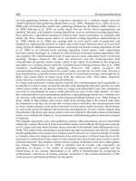
BOW/STERN THRUSTER UNITS
Elliott White Gill 360° Thrust and Propulsion Units
Over the last twenty years thrust units have proved themselves in all
aspects of ship-handling. Advances in design, power and control have all
led to the development of bigger thrusters and better performance.
Vertical shaft type unit
Horizontal shaft type unit
P & S
Intakes
T3 type unit
Sea
chest
Shallow draught
barge type unit
Figure 9.14 Elliott White Gill 360° thrust and propulsion units.
224 Seamanship Techniques
28. Bow thrust units as manufactured by Elliott Turbomachinery Ltd. These thrusters provide steering control without the use of rudders and main
engines. Four models are available, capable of delivering thrusts of up to 17,000 kg. They are, shown clockwise from upper left, the Vertical Shaft,
the T–3, the Cross Shaft and the Horizontal Shaft designs.
225Ship-Handling
The Elliott White Gill 360° thruster unit (Figure 9.14) has some
distinct advantages over the conventional ‘tunnel thruster’. Not only can
the force of the thrust be directed as the operator desires but with its
location totally submerged all the time there is little chance of damage
from surface obstructions.
The position of installation is so far beneath the water surface that the
performance is not impaired by heavy weather. Pitching or heavy rolling
have little or no effect as the intakes rarely break surface, if at all. Limited
maintenance is required, with the unit being readily accessible from
within the vessel. No part of the unit projects beyond the lines of the
hull.
Bow thrust units are further illustrated in Plate 28.
Elliott White Gill 360° Trainable Thrust Units
The main ship-handling features of the 360° trainable thruster (Figure
9.15) are:
1. The thruster may be used as an auxiliary means of power or propulsion,
being employed for both propulsion and steering of the vessel.
2. It is capable of turning a vessel in its own length and turning
‘broadside’ on without resorting to the use of main engines and/or
rudder.
3. Remote control of thruster unit is achieved from a main control
bridge panel. Additional bridge wing control panels may be fitted as
required.
4. The thrust capacity of up to 17 tonnes can hold the vessel on station
even in bad weather or heavy sea conditions.
Figure 9.15 Elliott White Gill 360° trainable thrust units.
Essu
FIN STABILISERS
There are two principal methods of reducing roll by means of stabilisation
available to the shipowner:
(a) Active fin – folding (Figures 9.16 and 9.17) or retractable type.
(b) Free surface tanks.
226 Seamanship Techniques
Hydraulic
oil pipes
Gravity feed
lubrication
Piston
rod
House/extend
cylinder
Fin angle
transmitter
Lubrication/
pressure pipes
trunnion
Hull
Crux
head
seal
Fin box
Crux
box
Rack on
vane motor
rotor
Gear
case
Resilient
coupling
Fin tilting
vane motor
Fin
House/extend
lever
Top
trunnion
bracket
Upper main
bearing seal
Crux
Relieved
crux section
for lubrication
Fin
shaft
Pinion
Bottom
trunnion
bracket
Main
seal
Toothed sector
or vane motor
stator
Tailflap
seal
Toothed
quadrant
on tailflap
stock
Fin
sleeve
Tapered
roller
bearing
Figure 9.16 Fin stabilisers.
Actuating machinery is
provided to rotate fins in
either positive or negative
angles of incidence
Fin angle Transmitters (Tx).
These contain rotary
potentiometers driven
directly from the fin through
a shaft and bevel gear
arrangement. They provide
electrical fin-angle signals
for feedback of control
and indication.
Fin angle Tx
Bridge
control
panel
Fin unit
Fin
Power
unit
Fins, fitted at the
turn of the bilge and
constructed in
fabricated or cast
steel, fold forward
to be housed in
recesses in the ship’s
hull.
Compartment
control
panel
Power
unit
Fin
angle
controlFin
Fin angle Tx
Fin unit
Both systems have their merits, but the fin types would appear to be
unrivalled when fitted to vessels engaged at speeds in excess of 15 knots.
Should the vessel be operating at low speeds or at anchor in an exposed
Figure 9.17 Folding fin stabiliser unit.
227Ship-Handling
position, then a free surface tank system may be better suited for the
nature of work.
MANOEUVRING WITH MOORING LINES
The main function of mooring lines, be they wire or fibre ropes, is to
retain the vessel in position. However, there are times when they may be
used in the turning or manoeuvring of the vessel, as when entering a
dock or coming off quays (see Figures 9.18 and 9.19).
FAIRLEADS
The roller fairlead is often encountered as a double or even treble lead,
but is also found as a single lead on a stand or pedestal (Figure 9.20). It
is in common use aboard a great many modern vessels, where it is
generally referred too as an ‘old man’ or a ‘dead man’ because of its static
pose. It has proved its usefulness in mooring operations for altering the
lead of a rope or wire through very sharp angles.
Maintenance should be on a regular basis with regard to greasing and
oiling about the axis. The pedestal should be painted at regular intervals
to prevent corrosion. Should a lead of this type become seized it is
normal to soak the moving parts in release oil and then attempt to free
the roller lead by use of a mooring rope to the warping drum end, so
creating a friction drive.
Universal Multi-angled Fairlead
This fairlead (Figure 9.21) consists of two pairs of axial bearing rollers,
one pair in the vertical plane and the other pair in the horizontal. The
main advantage of this type of lead is that it provides a very wide angular
range not only in the horizontal and vertical planes but also in any
oblique plane.
The main disadvantage of the lead is that it requires regular maintenance
in the way of periodic greasing through grease nipples at each end of the
rollers. When compared with the panama lead, the rollers respond when
mooring lines are under tension, so that friction is reduced, whereas the
panama lead has no moving parts and friction may cause limited damage.
Universal leads are regularly found on the quarter and shoulder areas
of the vessel for the multiple use of spring or head and stern lines.
Panama Lead
This type of lead is very common aboard modern vessels.
It may be a free standing lead, as shown in Figure 9.22, in which case
the underdeck area is strengthened, or it may be set into bulwarks and
strengthened by a doubling plate. The lead is one favoured by seafarers
because the rope or wire cannot jump accidentally when under weight.
BOLLARDS (BITTS)
The term ‘bollard’ is usually applied to a mooring post found on the
quayside and ‘bitts’ to the twin posts found on ships (Figure 9.23).
Quayside
CDE
B
A
FG H
I
Key A, B, C Sternlines
D Breastline
E After spring
F Forward spring
G Breastline
H, I Headlines
Figure 9.18 Example of moorings used to secure vessel
to quay.
Weld
Deck plating
(stiffened)
Pedestal securely
welded to deck
Fairlead free to rotate
Figure 9.20 Roller fairlead.
Figure 9.19 Mooring rope used as a bight (above) and
as an eye and a bight (below).
Quayside
Bollard
Bight of mooring
rope
Vessel alongside
The eye splices are kept
well clear of the bitts
Quayside
Bollard
Alternative bollard
Use of eye and
bight
Vessel alongside
228 Seamanship Techniques
RIGGING SLIP WIRES OR ROPES
The purpose of the slip wire is to enable the vessel to let herself go, at
any time, without being dependent on the port’s linesmen to clear lines
from bollards. It is generally always the last line to let go. In some
circumstances a slip rope may be used (see Figure 9.24).
Slip wires tend to run easily when letting go and heaving taut, but the
wire is heavy and often difficult to handle. A strong messenger must be
employed to heave the eye back aboard when rigging, because the wire
will not float as a rope may, and there may be a long drift between the
bow or stern and the bollard buoy.
Slip ropes are easier to handle and manipulate through the ring of a
mooring buoy, but they are bulky and slow in running because of surface
friction between the rope and buoy ring. They generally float on the
surface when going out to the buoy and when being heaved back
aboard, this fact considerably reduces the weight on the messenger.
Whether a wire or rope is to be used, a prudent seaman will always
seize the eye of the slip to allow clear passage through the ring of a
mooring buoy.
Operation
Arrange the slip wire in long flakes down the deck length, then pass the
eye down into the mooring boat. Additional slack on the wire should be
given to the boat and coiled down on the boat’s bottom boards. This
provides the boat handler with slack to ease the weight, should the slip
become snagged aboard. Pass a messenger into the mooring boat with
the slip wire, but do not make the messenger fast to the slip wire at this
stage.
Frame with
rounded edges
Metal
rollers
(axial bearing)
Double plate
Figure 9.21 Universal multi-angled fairlead.
Elevation
Drain hole
Lead aperture
Strengthened deck
Section
Figure 9.22 Panama lead.
Bolts
Hollow
casting
Hollow
dias
Weld
Deck plating (stiffened)
Hollow steel casting
Through bolt
Deck plating
Wood sole piece
Fore and aft
tie plate
Weld
A third type (fabricated from steel plate and tubing)
is available and this will be welded into position on a
strengthened deck location.
Figure 9.23 Bollards and bitts.
Athwartship beam
229Ship-Handling
As the mooring boat travels towards the buoy, pay out both slip wire
and messenger. A man wearing a lifejacket should then ‘jump the buoy’,
pass the seized end of the slip through the ring, then secure the messenger
to the small part of the eye of the slip wire. The messenger should never
be passed through the ring of the buoy first, for this may cause the hitch
to jam in the ring of the buoy when heaving back aboard. Signal to the
officer in charge aboard the vessel to heave away on the messenger and
bring the slip wire back aboard. Detach the messenger and turn up both
parts of the slip wire in ‘figure eights’ on the bitts. Do not put the eyes
of the slip on the bitts, as this would make letting go difficult if weight
is on the wire.
Mooring buoy
Single-eye
mooring ropes
Seized
eye
Slip
wire
Messenger
2
1
Pass eye of slip wire
through buoy ring
before securing
messenger
Messenger
secured
3
4
Figure 9.24 Rigging of slip wires.
A port mooring boat will be required for this operation,
together with a lifejacket for the man engaged in buoy
jumping and dipping the lines through the ring of the
buoy.
1. Secure the forward or after end to the buoy in order
to steady the vessel before passing the slip wire.
2. Prepare the slip wire beforehand by seizing the eye
of the wire to enable it to pass through the ring of
the buoy. Flake a messenger to the mooring boat
with the slip.
3. Dip the slip wire through the ring of the buoy and
secure the messenger to it. Once the small boat is
clear, signal the vessel to heave the slip wire aboard,
via the messenger.
4. Once the slip wire is aboard, release the messenger
and turn up the slip wire on the bollards. Do not
place eyes over bitts, as this may restrict letting go
when weight is on the wire.
230 Seamanship Techniques
BERTHING
Let us assume that no tugs are available and that the ship has a right-hand
fixed propeller (see Figures 9.25 and 9.26).
3
2
1
Figure 9.25 Berthing, wind onshore, tidal conditions calm.
1. Stop the vessel over the ground in a position with the ship’s bow
approximately level with the middle of the berth. Let go offshore
anchor.
2. Control the rate of approach of the vessel towards the berth by
ahead movements on main engines, checking and easing out anchor
cable as required. Try and keep the vessel parallel to the berth.
3. Check cable within heaving line distance of the berth. Make fast
fore and aft. Slack down cable when alongside.
1
2
Figure 9.26 Berthing, wind offshore, tidal conditions calm.
1. Approach berth at a wide angle to reduce wind effect and prevent
the bow from paying off.
2. Slowly approach berth and maintain position over ground.
3. Pass head line and stern line together from the bow area.
4. Stay dead slow astern on main engines, ease head line and at the
same time take up the weight and any slack on the stern line. Draw
the vessel alongside and secure. Depending on the strength of the
wind, it would be advisable to secure a breast line forward as well
as additional lines fore and aft as soon as practicable.
1
2
Figure 9.27(a) Clearing a berth, wind and tide astern.
1. Single up to stern line and forward spring.
2. Main engine astern, ease out on stern line until stern is well clear of quay.
3. Let go and take in stern line. Let go forward.
4. When well clear of quay, stop main engine. Put rudder to port, and go ahead on main
engine.
CLEARING A BERTH
Let us assume that no tugs are available and that the ship has a right-hand
fixed propeller (see Figures 9.27 to 9.30).
231Ship-Handling
1
2
1
2
Figure 9.27(b) Clearing a berth, no tugs available, right-hand fixed propeller.
1. Single up to a head line and stern line.
2. Let vessel blow off the quay: keeping the vessel parallel to the quay by
checking and controlling lines forward and aft.
3. When clear of the quay, let go fore and aft lines. Half ahead followed
by full ahead on main engines if circumstances permit. Rudder applied
as appropriate.
Figure 9.28 Clearing a berth, wind and tide ahead.
1. Single up to a head line and aft spring.
2. Ease away head line, rudder to starboard. With the tidal effect between
the bow and the quayside the ship’s bow should pay off.
3. Ease out on head line, slow ahead on main engines, take in head line
and pick up slack on aft spring. Let go and take in aft spring. Use
engine and rudder as appropriate.
Figure 9.29 Clearing a berth, port side to, no wind or tide.
1. Single up forward to an offshore head line and forward spring.
2. Keeping the weight on the forward spring, heave on the head line in
order to cant the stern away from the quay wall. The stern will make
a more acute angle with the quay if the main engine is ordered ‘dead’
slow ahead and the rudder put hard to port. Care should be taken to
avoid putting the stem against the quay wall, especially if the vessel is
of a ‘soft nose’ construction. Let go in the forepart.
3. Put main engines astern and allow the vessel to gather sternway to
clear berth.
Figure 9.30 Clearing a berth, starboard side to, no wind or tide.
1. Single up forward to an offshore head line and forward spring.
2. Heave on the head line to bring the stern away from the quay wall.
It may be necessary to double up the forward spring with the intention
of using an ahead engine movement, allowing the spring to take the
full weight, and effectively throwing the stern out from the quay. Let
go smartly forward, main engines astern. When vessel gathers sternway,
stop.
3. When clear forward, put rudder hard aport, and main engine full
ahead.
1
2
3
3
2
1
232 Seamanship Techniques
Figure 9.31 Entering dock, wind and tide astern.
1. The vessel should turn ‘short round’ (Figure 9.38) or snub round with use of starboard
anchor. The ship will then be in a position of stemming the wind and tide and should
manoeuvre to land ‘port side to’ alongside the berth below the dock.
2. Secure the vessel by head lines and aft spring to counter tide effect and keep her
alongside.
3. Put main engines slow ahead to bring the ‘knuckle’ of the dock entrance midships on
the vessel’s port side. Pass a second head line from the starboard bow across the dock
entrance to the far side. Take the weight on this head line. Let go aft spring. As the
vessel comes up to the knuckle, ease the port head line until the ship’s head is in the
lock, then heave on the port head line to bring ship parallel to sides of lock.
4. Carry up head lines alternately from each bow. Send out stern line and forward spring
once the vessel is inside the dock. Stop main engines and check ahead motion as
appropriate.
‘A’
1
2
‘B’
Figure 9.32 Securing to buoys, no wind or tide.
1. Approach the buoy ‘A’ slowly, with the buoy at a fine angle on the starboard bow, to
allow for transverse thrust when going astern.
2. Stop the vessel over the ground and pass head and then stern lines. Align vessel
between buoys ‘A’ and ‘B’ by use of moorings, and secure fore and aft.
‘B’
1
2
‘A’
Figure 9.33 Securing to buoys, wind and tide ahead.
1. The vessel should stem the tide and manoeuvre to a position with buoy ‘A’ just off the
port bow. It may be necessary for the vessel to turn short round or snub round on an
anchor before stemming the tide. Adjust main engine speed so that the vessel stops over
the ground. Pass head line.
2. Although an astern movement of main engines would cause the bow to move to port,
if required, holding on to the head line would achieve the same objective, by allowing
the tide/current to effect the desired movement from position ‘1’ to position ‘2’. Pass
stern line once vessel is aligned between the two buoys ‘A’ and ‘B’.
2
1
‘B’
‘A’
3
Figure 9.34 Securing to buoys, wind and tide astern.
1. Vessel under sternway, stern of the vessel seeking the eye of the wind. Use of rudder
may assist to bring buoy ‘A’ on to the starboard quarter.
2. Run stern line from starboard quarter and make fast.
3. The vessel could expect to be moved by wind and tide to a position between the two
buoys. The vessel may then be secured forward by head lines to buoy ‘B’.
4. The success of this manoeuvre will, of course, depend on the strength of wind and
tide. It might be necessary to turn the ship around to stem wind and tide, or, if the ship
is to lie in the direction shown, it might be necessary to turn the ship and secure the
bow to the other buoy shown and allow her to swing with the change of tide.
Care should be taken that any stern lines are kept clear of the propeller when the vessel
is navigating stern first.
1
2
3
4
Prudent use of
pudding fender on this
knuckle may prevent
damage should the vessel
land heavily
ENTERING
DOCK
No tugs are available and the ship has a right-hand fixed propeller (see
Figure 9.31).
SECURING TO BUOYS
No tugs are available and the ship has a right-hand fixed propeller (see
Figures 9.32 to 9.35).
233Ship-Handling
MOORING
The term mooring is used in conjunction with the securing of the
vessel, either by two anchors or to a mooring buoy. The term is often
used when vessels are moored to a jetty or quay by means of mooring
ropes (Plate 29). The term may be considered, therefore, to be rather a
loose one, applying to several methods of securing a ship. Most seafarers
consider it to mean ‘mooring with two anchors’, in the form of a
running moor, standing moor or open moor.
‘A’
1
2
‘B’
3
Figure 9.35 Securing to buoys, no wind or tide.
1. Approach buoy ‘B’ at a fine angle on the starboard
bow. Pass head line and overrun the buoy about a
third of the vessel’s length from the bow. Hold on to
the head line to check the vessel’s headway. Allow
the head line to act as a spring.
2. Rudder hard a-starboard, main engines ahead to turn
the vessel about buoy ‘B’.
3. Astern movement on engines will cause the port
quarter to close towards buoy ‘A’. This motion will
further be assisted by the transverse thrust effect of
the propeller. When the vessel is aligned between
buoys, secure fore and aft.
‘B’
1
2
3
‘A’
Figure 9.36 Letting go from buoys wind and tide ahead.
1. Let go stern line from buoy ‘B’. When clear aft, apply
starboard helm and go dead slow ahead on main engines.
2. As the vessel’s bow moves to starboard, ease the head
line. When clear of buoy ‘A’, let the head line go
forward.
3. Main engines ahead, port rudder.
Figure 9.37 Letting go from buoys, wind and tide astern.
1. Slack stern line to see if the vessel will ‘cant’ away from buoy ‘A’.
2. If the vessel cants, let go head line, with main engines half astern.
Port helm and allow vessel to gather sternway.
3. When the vessel clears buoy ‘A’, let go stern line. Main engines
ahead once stern line is clear of propeller, helm hard a-port.
If the vessel will not ‘cant’, let go the head line and heave the vessel
close up to buoy ‘A’; put rudder hard a-port, let go aft, with main
engines full ahead.
Once headway is gathered, make sharp helm movement to hard a-
starboard to throw the stern clear of the buoy.
‘B’
1
2
3
‘A’
LETTING
GO FROM BUOYS
No tugs are available and the ship has a right-hand fixed propeller (see
Figures 9.36 and 9.37).
234 Seamanship Techniques
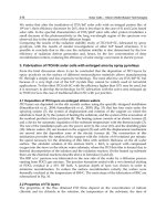
TURNING VESSEL SHORT ROUND
The ship has a right-hand fixed propeller (see Figure 9.38).
Running Moor
In all ship-handling situations the vessel should stem the tide if control
is to be maintained. The running moor operation (Figure 9.39) is no
exception to this rule, and should the tidal stream be astern of the vessel,
then she should be manoeuvred to stem the tide, either by turning short
round or snubbing round on an anchor. This will not always be possible
however, and the running moor may have to be made with the tide. A
running moor procedure is as follows:
1. Speed over the ground should be 4–5 knots, preferred depth of
water being dependent on draught, and good holding ground chosen
if possible. Let go the weather anchor, so that the vessel will be blown
down from the anchor cable before she reaches the desired position.
2. Continue to make headway, paying out the cable of the anchor which
has been let go. Continue to pay out the cable up to eight or nine
shackles, depending on the amount of cable carried aboard and the
depth of water. The vessel will overrun the desired mooring position.
3. The vessel should start to drop astern as the engines are stopped. Let
go the lee anchor and pay out the cable. Start heaving away on the
weather anchor cable to bring the vessel up between the two anchors.
The vessel may require an astern movement on the engines to begin
drawing astern.
In comparison with the standing moor the ship’s machinery is running
and operational throughout the manoeuvre. In the standing moor the
vessel’s machinery could well be out of action, standing still, while the
vessel drops astern with the tidal stream.
1
2
4
3
5
Figure 9.38 Turning a vessel short round.
The vessel is equipped with a right-hand fixed propeller,
and, when turning ‘short round’, she would turn more
easily to starboard than to port.
1. Start the manoeuvre from the port side of the channel
to provide the maximum distance for the headreach
movement of the vessel.
2. Rudder hard a-starboard, main engines full ahead.
Stop engines. Do not allow the vessel to gather to
much headway.
3. Rudder midships, main engines full astern.
4. As sternway is gathered, the bow of the vessel will
cant to starboard while the port quarter will move in
opposition, owing to the effects of the transverse
thrust. Stop engines.
5. Rudder to starboard, engines ahead.
29. Vessel moored alongside a quay, secured by two
head lines and a rope spring led aft from the starboard
shoulder. The port anchor, having been let go during
the berthing operation, has been left with the cable
in the ‘up and down’ position for the purpose of
heaving the vessel off the berth when letting go.
Panama leads are clearly visible, one of them a
centre lead. Triple roller fairleads are to be seen on
either bow.
235Ship-Handling
Standing Moor
The vessel must stem the tide, in order to retain control of the operation
(Figure 9.40), which proceeds as follows:
1. The vessel should be head to tide, stopped over the ground. Sternway
should be gathered either by the tidal stream or operating astern
propulsion. Let go the lee anchor (riding cable) and allow the vessel
to drop astern. Pay out the anchor cable as sternway is gathered, up
to 8–9 shackles, depending on the amount of cable carried aboard
and the depth of water.
2. Take the sternway off the vessel by use of engines ahead and checking
on the weight of the cable. Order maximum helm away from the
released anchor, and engines ahead to cant the vessel before letting
go the weather anchor (sleeping cable). The mariner should continue
to use engines ahead or astern as necessary to ease the weight on the
windlass as the vessel heaves on the riding cable.
1 Stem the tide
let go the weather anchor
2 Pay out on cable,
let go second anchor
Tide
Tide
Wind
Cable being paid out
Resultant motion
Vessel
moving
ahead
Cable continuing to be paid out
Amount of cable to
use will depend
on depth of water.
Approximately eight
shackles is usual.
Cant the bow by rudder
action away from the
line of the first anchor.
This action would not be
necessary if the wind was
causing the vessel to set down.
3 Pay out second anchor cable,
heave in on first cable
Tide
Sleeping cable
Heave on this cable
Vessel
brought up between
two anchors
Pay out this
cable
Riding cable
Figure 9.39 Running moor.
236 Seamanship Techniques
3. Continue to heave on the riding cable and pay out the sleeping
cable until the vessel is brought up between the two anchors.
A standing moor is sometimes preferred to a running moor when the
tidal stream is very strong. The standing moor in theory could be carried
out by just allowing the tidal stream and the windlass to do the work.
The main danger of mooring with two anchors is the possibility of
causing a foul hawse when the vessel swings with the turn of the tide. To
reduce this most undesirable condition the Royal Navy tends to use a
mooring swivel, joining the two cables. Merchant vessels would not
generally carry such a swivel, unless it is intended to secure the vessel to
a semi-permanent mooring over an indefinite period of time.
OPEN MOOR
The open moor (Figure 9.41) is used extensively when additional holding
power is required. It would be employed when a single anchor would
not provide enough weight to hold the vessel and prevent the ship from
dragging.
Possibly the best method of approach is to stem the current and/or
head the wind, and position the vessel to let go the windward anchor.
1 Stem the tide,
let go lee anchor
Wind
Vessel
moving
astern
Tide
2 Pay out on cable,
let go second anchor
Cable continuing to be paid out as vessel moves astern
Ahead, on
engines and use
rudder action to
cant bow away
from line of
first anchor.
Tide
Amount of cable to use
will depend on
depth of water.
Approximately 8 shackles is
usual.
Pay out second anchor cable,
heave in on first cable
Riding cable
Heave on this cable
Tide
Vessel
brought up between
two anchors
Pay out this
cable
Sleeping cable
Figure 9.40 Standing moor.
Circle of swing
before anchors
become fouled
Port anchor
Radii = Cable scope
Starboard anchor
Figure 9.41 Open moor.
3
237Ship-Handling
Once this first anchor has been ‘let go’ pay out on the cable with
simultaneous ‘ahead movements on engines’ to manoeuvre the vessel
towards a position of letting go the second anchor. Extensive use of
rudder and engines may be required to achieve this second desired
position.
Once the second position is attained, let go the second anchor, order
astern movement of the engines, and pay out on the second anchor
cable. The first anchor cable will act as a check until both cables have an
even scope, once this situation is achieved then cables can be payed out
together as required to obtain the final position of mooring.
Masters should bear in mind that with this method, the first anchor
may be turned out of the holding ground when the vessel gathers
sternway after the second anchor has been released. To this end it may
become prudent to check both cables prior to coming to rest, so ensuring
that both the second and the first anchors are bedded in and holding.
Baltic Moor
The vessel should approach the berth with the wind on the beam or
slightly abaft the beam. The stern mooring wire should be secured in
bights by light seizings in the forward direction to join the ganger length
of the anchor cable before the approach is begun. Then proceed as
follows:
1. Manoeuvre the vessel to a distance off the berth of two or three
shackles of cable. This distance will vary with the wind force and
expected weather conditions.
30. Cruise ship moored, deploying both Port and
Starboard anchors. N.B. Additional centre anchor
in stowed position.
Quay
2
1
Anchor walked back clear of
hawse pipe
Stern mooring passed
forward in bights
Wind
Moorings fore and aft
prevent vessel ‘ranging’
4
3
Wind
Offshore anchor Let Go
Stern mooring secured to
ganger length
Position ‘3’ parallel
to berth
Figure 9.42 Baltic moor.
238 Seamanship Techniques
2. Let go the offshore (starboard) anchor. The weight of the anchor
and cable will cause the sail twine securing on the mooring wire to
part, and as the cable pays out, so will the stern mooring wire.
3. Let the wind push the vessel alongside, while you pay out the cable
and the stern wire evenly together.
4. Use ship’s fenders along the inshore side between the vessel and the
quay, then pass head and stern lines as soon as practical.
5. Secure head and stern lines on the bitts before taking the weight on
the anchor cable and the stern mooring wire. This tends to harden
up the inshore (port) moorings.
One reason behind the Baltic moor is that many ports experience strong
Onshore winds.
When the vessel comes to let go and depart the port, unless she is
fitted with bow thrust units, the Master may encounter difficulties in
clearing the berth. However, heaving on the anchor cable and on the
stern mooring will allow the vessel to be bodily drawn off the quay.
Once clear of the berth, full use can be made of engines and helm to get
under way.
The main disadvantage of this moor is that time is required to let the
stern mooring go from anchor/cable. To this end the size of shackle
used and the possibility of allowing it to pass up the hawse pipe are
critical factors. Alternatives are to find a lee for the vessel for the purpose
of disengaging the stern mooring.
Mediterranean Moor
This moor is carried out usually for one of two reasons – either quay
space is restricted and several vessels are required to secure or a stern
loading/discharge is required. (As for a tanker.) The object of the manoeuvre
is to position the vessel stern to the quay with both anchors out in the
form of an open moor. The stern of the vessel is secured by hawsers
from the ship’s quarters to the quay.
This type of mooring (Figure 9.43) is not unusual for tankers using
a stern load or discharge system. However, a disadvantage to the dry
cargo vessel lies in the fact that cargo must be discharged into barges. It
is not a favourable position in bad weather and there is a distinct possibility
of fouling anchor cables, especially when other vessels are moored in a
similar manner close by. The procedure is as follows:
1. Approach the berth, as near parallel as possible to the quay. Let go
the offshore anchor. Main engines should be ahead and dead slow.
2. Rudder should be positioned hard over to turn the vessel away from
the quay. Continue to let the cable run, and pay out as the vessel
moves ahead. A check on the cable as the vessel starts to turn would
accentuate the turn, and produce astern-to orientation for the vessel.
Stop main engines.
3. Let go the second anchor, and come astern on main engines, paying
out the cable on the second anchor. As the vessel gathers sternway,
239Ship-Handling
recover any slack cable on the offshore anchor. Stop engines and
check the sternway on the vessel, as required, by braking on the cables.
4. Manoeuvre the vessel to within heaving line distance of the quay by
use of engines and cable operations. Pass stern moorings to the quay.
Tension on the moorings is achieved by putting weight on to the
cables once the moorings have been secured on bitts.
Dredging Down
A vessel is said to be ‘dredging down’ when she is head to the wind and/
or tide (stemming the tide), with an anchor just on the bottom. The
amount of cable out is limited to the minimum to put the anchor on the
bottom. Dredging down occurs when the vessel is not moving as fast as
the current, which makes the rudder effective and allows the ship to
manoeuvre. It is normal to expect a crabwise motion of the vessel over
the ground, which is often employed for berthing operations. Used in
conjunction with bold helm, the direction of the ship’s head can be
appreciably changed.
Snubbing Round
A vessel can turn head to tide without too much difficulty, provided that
there is sufficient sea room to do so. Should the sea room not be available
then a tighter turn will be required. This can be achieved by means of
one of the ship’s anchors, in the operation of snubbing round on the
weight of the cable.
It is most frequently practised when the vessel has the tidal stream
astern or in berthing operations. The vessel’s speed should be reduced so
that she can just maintain steerage way. Let go either the port or star-
board anchors, at short stay, and allow the cable to lead aft, dragging the
Quay
Stern
moorings
4
3
2
Engine –
1
/
2
Second Anchor
Engine +
1
/
2
,
helm
hard to
stbd
Offshore anchor
1
Port helm,
engine
+
1
/
4
Figure 9.43 Mediterranean moor.
240 Seamanship Techniques
anchor along the bottom. The cable will act as a spring, reducing headway,
and canting the bow round towards the side from which the anchor was
let go. The Master or pilot of the vessel should supplement this anchor/
cable action by use of maximum helm and increase in engine power to
bring the vessel through 180°. The anchor party should be briefed on
the operation beforehand, and know, when to apply the brake to the
cable, so giving the check on the vessel’s forward motion that is necessary
to complete the turn.
If the manoeuvre is attempted with too much headway on the vessel,
excessive weight will be brought on to the cable as the vessel turns,
which could result in the cable parting. In general practice, the anchor
is let go to about a shackle, depending on the depth of water. The brake
is then applied to start the turning motion on the vessel.
Anchoring in an Emergency
A vessel is approaching a channel in reduced visibility, speed 5 knots. The
officer of the watch receives a VHF communication that the channel has
become blocked by a collision at the main entrance (Figure 9.44). What
would be a recommended course of action when the vessel was 1 mile
from the obstructed channel, with a flood tide of approximately 4 knots
running astern?
1. Assuming the vessel to have a right-hand fixed propeller, put the
rudder hard a-starboard and stop main engines. The vessel would
respond by turning to starboard. The anchor party should stand by
forward to let go starboard anchor.
2. Let go starboard anchor. Full astern on main engines to reduce
headreach. Letting go the anchor would check the headway of the
vessel and act to snub the vessel round. Stop main engines.
3. Full ahead on main engines, with rudder hard a-starboard. Ease and
check the cable as weight comes on the anchor. Once the vessel has
stopped over the ground, go half ahead on main engines, allowing
the vessel to come up towards the anchor and so relieve the strain
on the cable. Heave away on the cable and bring the anchor home.
Clear the area and investigate a safe anchorage or alternative port
until channel obstruction is cleared.
INTERACTION
Most vessels will at one time or another experience some form of
interaction with another vessel, perhaps through navigating in shallow
water or passing too close to an obstruction. In this age of the big ship
Masters and pilots should know exactly what interaction is and what the
results of its occurrence may be.
Interaction is the reaction of the ship’s hull to pressure exerted on its
underwater volume. This pressure may take several forms (Figures 9.45
to 9.48).
4
3
2
1
Flood tide astern of vessel
Vessel at a range
of 1 mile from
obstruction
Figure 9.44 Emergency anchor to avoid obstruction.
Collision between
two vessels obstructs
the navigation of the
channel
241Ship-Handling
Interaction in Narrow Channels
Vessels navigating in narrow channels (Figures 9.49 to 9.51) may also see
telltale signs of interaction, e.g. when passing another vessel which is
moored fore and aft. The interaction between the vessels will often cause
the moored vessel to ‘range on her moorings’. A prudent watchkeeper
on that vessel would ensure that all moorings were tended regularly and
kept taut. The experienced ship-handler would reduce speed when passing
the moored vessel to eliminate the possibility of parting her mooring
lines.
Another telltale sign, again in a narrow channel such as a canal, may
be noticed when a vessel is navigating close to the bank. As the vessel
proceeds, a volume of water equal to the ship’s displacement is pushed
ahead and to the sides of the vessel. The water reaches the bank and rides
up it. Once the vessel has passed, the water falls back into the cavity in
the ship’s wake. The interaction in this case is between the hull of the
ship and sides of the bank. An increase in squat may be experienced
because of the loss of water under the vessel’s keel. This may even bring
about the vessel grounding. The effects may be reduced by a reduction
in speed, provided steering is not impaired by such action.
Attention is drawn to MGN 18 regarding Interaction between Ships.
SHALLOW WATER EFFECTS AND SQUAT
When a vessel enters shallow water, she experiences a restricted flow of
water under the keel, which causes an apparent increase in the velocity
of water around the vessel relative to the ship’s speed. Consequently, an
increase in the frictional resistance from the ship’s hull will result.
If the increase in the velocity of water is considered in relation to the
pressure under the hull form, a reduction of pressure will be experienced,
causing the ship to settle deeper in the water. The increase in the frictional
resistance of the vessel, together with the reduction of pressure, may
result in the ship ‘smelling the bottom’. A cushion effect may be experienced,
causing an initial attraction towards shallow water, followed by a more
distinct ‘sheer’ away to deeper water.
Where shallow water is encountered in confined waters, e.g. channels
and canals, a ‘blockage factor’ (Figure 9.50) must be taken into account.
Ships may sink lower in the water when the blockage factor lies between
0.1 and 0.3; this, combined with a change of trim from the shallow water
effect, is generally expressed as ‘squat’. The result of a vessel squatting will
be a loss of clearance under the keel, making steering and handling
difficult.
Vessels navigating with a blockage factor between 0.1 and 0.3 push a
volume of water ahead. This water, carried back along the sides of the
channel to fill the void left astern of the ship, is often referred to as the
‘return current’. The rate of the returning water has an effect on the
ship’s speed, and the maximum speed that the vessel can reach becomes
a limited factor known as ‘canal speed’.
Bows repel
Sterns
attract
Figure 9.45 Overtaking, when two vessels are passing
too close to each other on parallel courses.
Interaction may occur when the vessels
are abeam, resulting in deflection of the
bows and attraction of stern quarters, with
dangerous consequences.
Sterns attract
Bow, foreparts repelled
Figure 9.46 Interaction between two vessels on reciprocal
courses.
The period of time in which interaction is allowed to
affect both vessels is limited because the pressures and
water cushions created only last during the period of
passing. When vessels are on reciprocal courses, the length
of time that the vessels are actually abeam of each other
is short (as opposed to one vessel overtaking another).
No problems arise when both vessels have ample sea
room. However, in narrow channels there is the danger
of grounding or collision as bows are repelled and sterns
pulled towards each other.
242 Seamanship Techniques
Influencing Factors on Squat
1. The speed of the vessel.
2. The rpm in relation to the ‘canal speed’.
3. The type of bow construction, which will affect the bow wave and
distribution of pressure.
4. The position of the longitudinal centre of buoyancy (LCB), near or
through which the downward force of squat will probably act.
Squat may occur by the head or by the stern. If the LCB is aft of the
centre of flotation, a squat by the stern would be expected; and if the
LCB is forward of the centre of flotation, the vessel would be expected
to settle by the head.
The strongest influence on the amount of squat will be the speed of
the vessel. As a general guide, squat is proportional to the square of the
speed. A reduction in speed will lead to a corresponding reduction in
squat.
WORKING WITH TUGS
The function of the tug is to assist the pilotage of a vessel. This function
has brought many types of tug into being, the most common being the
ocean-going tug and the smaller dock tug (Figure 9.52 and Plate 31).
Extensive use of supply vessels in the dual-purpose role of supply and
towing have caused design and construction firms to add towing facilities
to many supply vessels. Use of tugs while entering a lock is shown in
Figure 9.53.
Area of bank cushion effect
Vessel experiences a massive
sheer away from the bank.
Area of
bank suction
effect
Area of
expected
sheer
Figure 9.47 Situations involving interaction.
Above, interaction occurring between a vessel and a bank,
sometimes referred to as a bank cushioning effect. A
vessel with helm amidships may create an area of increased
pressure between her hull and the bank. The result is that
the vessel appears to be repelled from the bank while her
stern is apparently sucked into the bank, with obvious
dangers to rudder and propellers.
Below, interaction occurring between the vessel’s hull
and the sea bed when in shallow water (shallow water
effect). When approaching a shallow water area, a vessel
may initially be attracted to the shelving or the obstruction.
However, as pressure builds up between the hull and the
sea bottom, the vessel may experience a sudden and
decisive sheer to one side or the other. Rudder effect
may also be reduced by turbulence caused by a reaction
from the sea bottom.
Tug
Tug
Large
vessel
Tug’s bow being
repelled by
pressure cushion
at shoulder
of large
vessel.
Figure 9.48 Interaction between large vessel and tug.
1. As the tug approaches the larger vessel to collect the
towline, its bow is repelled by the shoulder of the
larger vessel.
2. Counter helm is applied to correct the outward motion
of the tug.
3. As the tug moves ahead under the bow of the larger
vessel, it experiences an attraction to the larger vessel
accentuated by the tug carrying the counter helm.
4. Unless prompt action is taken by the helmsman on
the tug, the two vessels could collide, with the tug
passing in front and under the larger vessel’s bow.
243Ship-Handling
The very nature of the employment of tugs underlines the fact that
tremendous weight and stresses have come into play, with consequent
risk to operators. Many accidents have occurred in the past on mooring
operations, and a considerable number of these have been during the use
of tugs and their towlines.
Safe Handling of Towlines
1. Seamen should never stand in the close vicinity of a towline when
stress is seen to be in the line.
2. Towlines should always be let go in a controlled manner (by use of
rope tail from wire eye) to ensure that the tug’s crew are not
endangered.
3. Sharp angled leads should be avoided.
4. Chafe on towlines should be avoided, especially over long periods,
by parcelling the towline and lubricating any leads employed. Means
of adjusting the length of the towline to avoid continual wear and
tear or in the event of bad weather should be provided.
5. It is not considered good seamanlike practice to secure the eye of a
tug’s wire over the vessel’s bitts. The control of the station is then
passed to the tug, and the ship becomes dependent on the tug’s
Master to come astern. Effectively this eases the weight on the
towline and allows the ship’s personnel to slip the tow. However, in
an emergency, if the eye had been secured over the bitts, the ship’s
personnel would not have been able to release the towline.
6. When a ship’s towrope is released from a stern tug, in the majority
of operations main engines should be turning ahead. The screw race
will tend to push the towline well astern and clear of the propeller.
This also occurs with a towing wire when fitted with a nylon
pennant. The majority of man-made fibre ropes float as they are
stretched astern, providing the officer on station with more handling
time to bring the towline aboard, without fouling the propeller.
7. After any towline has been secured by turns aboard the vessel, the
weight should be taken to test the securing before the start of actual
towing operations.
8. Efficient communications should be established between the bridge,
the tug, and the officer on station, before starting the tow.
Girting or Girding
This is a term used to describe a tug being towed sideways by the vessel
she is supposed to be towing. The danger arises when the towing hook
is close to midships. The height of the towing hook is an important
factor, as are the speed and rate of swing of the towed vessel.
This situation could be extremely dangerous if the tug’s gunwales are
dragged under by the force of the vessel under tow acting on the towline,
especially if the weather deck of the tug has open hatchways. If in an
emergency the tug’s stern cannot be brought under the towline very
quickly, the tow should be slipped (see Figure 9.54).
a
b
b
a
e
d
c
c
d
e
Figure 9.49 Recommended passing positions for two
vessels in opposition in narrow channel.
The limits for vessels passing when navigating in narrow
channels can often be extremely fine. Both vessels are
recommended to reduce speed in ample time in order to
minimise the interaction between ship and ship and ship
and bank. Provided a sensible speed is adopted, it should
prove unnecessary to alter the engine speed while passing,
thus keeping disturbance and changing pressures to the
minimum as the vessels draw abeam.
In normal circumstances each vessel would keep to
her own starboard side of the channel (ab and cde), and
good communications should be established before the
approach to ascertain exactly when the manoeuvre will
start. Efficient port/harbour control can very often ease
situations like this simply by applying forward planning
to shipping movements.
b
d
D
B
Figure 9.50 Blockage factor.
Blockage factor
=×
b
B
d
D
Example
Let b = 45′; B = 100′; d = 26′; D = 78′
∴ Blockage factor
=
45
100
26
78
= 0.15×
244 Seamanship Techniques
Long-distance Towing
Should a vessel have to be towed, owing to engine failure or some other
reason, then she will require secure towing arrangements aboard. Experience
has shown that if an efficient method of securing is established at the
beginning of the towing operation, considerable time and effort will be
saved at a later date in the event of the towline parting.
One suggested method of forward securing is by means of a chain
cable bridle, constructed from one of the towed vessel’s anchor cables.
(Figure 9.55). An anchor will need to be hung off, either in the hawse
pipe or from the shoulder, leaving the second anchor housed in position
and clear ready for use, should it be required.
Preventer wires or relieving tackles, with the weight taken up, should
be secured to the bight of the bridle before the towline is secured to it
by a heavy duty shackle. Ample grease or other lubricant should be
applied to the fairleads and bollards which are expected to take the full
weight of the bridle once it is connected to the towing vessel.
The bearing surface of the chain bridle could be adjusted if relieving
tackles are used instead of preventer wires, and that would prevent
continuous chafe at any one point on the bridle. Lubrication and stress
on the bridle should regularly be checked, but personnel should in
general avoid the vicinity of the towline and bridle when weight is being
taken up by the towing vessel.
The preparation of the chain cable bridle is a lengthy one and mariners
should take account of the manpower required and the time to complete
the operation before expecting to get under way. Securing the bridle is
a lengthy process even in ideal weather conditions, but should the towline
part, say in heavy weather, the mariner may find the task of re-securing
the tow even more difficult.
a
b
A
c
d
Figure 9.51 Recommended positions when rounding a
bend (above) or overtaking another vessel
(below) in narrow channels.
31. Gob rope in use with a ship’s towline on the afterdeck of a docking tug. Tension is
achieved in the gob rope by means of a centre line capstan. The ‘towing rail’ is clearly
seen running a thwartships.
245Ship-Handling
32. Alternative type of gob rope (wire) and electric
winch.
Figure 9.52 Dock tug.
Rope fender
Tow hooks
Tow rope
Gob rope
slacked off
Rope
fender
Towing wire
Automatic winch
Towing rails
Afterdeck showing automatic towing winch
Bow
post
Shoulder
post
Towline
Capsizing moment
Ship’s motion
Figure 9.54 Girting or girding.
Eddy
Stern control
Pushing
Tidal stream
1–2 knots
Eddy
Forward motion
and alignment
Stern control
Holding
upwind
Tidal stream
2 knots
Fresh
breeze
Stern control
Tidal stream
2 knots
Pushing to check drift
Forward motion and guidance
Checking head line
Forward motion
Figure 9.53 Entering a lock – use and deployment of tugs.
246 Seamanship Techniques
Alternative Towing Methods
See Figure 9.56.
1. The towing vessel’s insurance wire can be combined with the anchor
cable of the vessel under tow. The wire from the towing vessel can
be secured around the mast, about the aft mast housing, the deck
house or the poop itself. Sharp leads will need to be well parcelled
and protected by wood to prevent chafe and the tow parting. The
main disadvantage of using the anchor cable of the towed vessel is
that the anchor is usually hung off at the shoulder, and the vessel
under tow cannot use this anchor in an emergency. This fact may
not seem important at the onset of the tow, but the anchor could
play an important role in reducing the ship’s momentum once the
destination has been reached. The obvious advantage of employing
the anchor cable is that the length of towline can be adjusted by
direct use of the windlass. The anchor may remain in the hawse
pipe, with the cable passing through the centre lead (bullring if
fitted).
2. An alternative method of towing is possible when the tug is fitted
with an automatic winch. The handling of the towline is made
relatively easy once the cable or chain bridle of the vessel under tow
has been secured. The lengthening and shortening of the towline is
carried out by manual operation of the winch, while the tension in
the towline is controlled automatically under normal towing
conditions. This method should not be attempted by vessels using a
conventional docking winch, as the additional strain brought to bear
on the axis of the winch could render it inoperative.
3. A wire towing bridle can be used. In this method the towing bridle
is secured to the vessel doing the towing operation, not the vessel
being towed. This bridle is rigidly secured in position by preventer
tackles and set around the after housing (poop area). Sharp corners
should be well parcelled to prevent chafe and lubricants applied to
bearing surfaces of the towline whenever necessary.
A combination of ‘rope spring’ and steel wire hawser is employed,
with the wire hawser being secured around four sets of bitts. The
main advantage of this method is that both anchors are left ready for
use, but adjusting the length of the towline can prove a lengthy and
sometimes dangerous task.
Fairleads
Chain bridle
Wire preventers
to deck rings
Ends of cable
forelock shackle
Figure 9.55 Method of securing chain bridle.
247Ship-Handling
1.
2.
3.
Towing vessel
Preventer
tackles
150 fathoms wire
60 fathoms of cable
Towed vessel with the
starboard anchor hung off,
and bare end of
cable shackled to
insurance wire hawser.
Insurance wire led via bitts about
the main mast house and secured to
bitts (with the eye) on the opposite
quarter to the tow.
Towing vessel fitted with
automatic winch
200–425 fathoms
of 56 mm steel wire
hawser
Towed vessel with the
starboard anchor hung
off, as above
This method should not be employed
without the automatic winch
Preventor easing
tackles
Towing bridle about the
after housing (32 mm wire)
Rope spring
100 fathoms of
32 mm steel wire hawser,
secured by means of four
sets of bitts.
Both anchors left available
for immediate use.
Figure 9.56 Towing methods.
Danger area for
possible collision
Leads should be
well greased and
bearing surface at
towlines
well lubricated to
avoid excessive chafe.
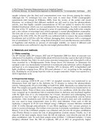
Figure 9.57 Towing by two tugs.
Use of Two Tugs
This method (Figure 9.57) has the obvious advantage of giving more
power on the towlines and increasing the speed of the tow. However, the
expense of employing two tugs instead of one is considerable, especially
if one tug can manage the job, though taking a little longer. Certain
heavy ULCC and VLCC vessels would, of course, need two or more
tugs.
The use of two tugs, one off each bow, has the effect of reducing the
yaw of the vessel under tow. Towlines secured on each side will vary in
length and construction but should be such as to lead approximately 30°
away from the fore and aft line of the parent vessel. This method is often
used for towing floating drydocks and the like, as it achieves greater
manoeuvrability.
Emergency Towing Arrangements for Large Tankers
In November 1983, the IMO adopted resolution A535(13) regarding
emergency towing arrangements applicable to new tankers of 20,000 or
over.
The purpose of the resolution, which was published in 1984, and
amended, was primarily to reduce the risks of pollution. Recommendations
regarding specialised fitments to applicable vessels are as follows:
Examples 1 and 2 show use of composite
towlines employing tugs towing spring and the
towed vessels anchor cable.