Robot manipulators trends and development 2010 Part 9 pot
Bạn đang xem bản rút gọn của tài liệu. Xem và tải ngay bản đầy đủ của tài liệu tại đây (1.44 MB, 40 trang )
RobotManipulators,TrendsandDevelopment312
a) b)
c)
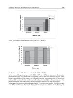
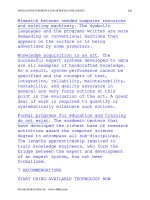
Fig. 15. Experimental values of absolute follow-up error signal of position a), velocity b) and
acceleration c)
6. Prototype of electro-pneumatic parallel 3-UPRR tripod manipulator
In the Division of Mechatronics (Kielce University of Technology, Poland) a prototype of
pneumatic translational parallel manipulator (PTPM) of tripod kinematic structure was
constructed (Dindorf et al., 2005; Laski & Dindorf, 2007). The prototype of tripod parallel
manipulator with Festo servopneumatic precision positioning systems is presented in
Fig. 1a. The manipulator possesses a supporting structure, fixed base, moving platform and
three pneumatic linear motions (servopneumatic axis). Each servopneumatic axis consists of:
rodless pneumatic cylinder type DGPIL-25-600 with integral feedback transducer (built-in
'Temposonic' encoders for continual positioning feedback to the master control unit), 5/3
servopneumatic valve (proportional directional control valve) type MPYE-5-1/8-HF-010B,
axis interface type SPC-AIF, positioning axis sub-controller type SPC-200 (the use of a sub-
controller card permits control of up to four axes) and Ethernet/Can Bus interface.
According to the systematics the prototype of 3-DoF pneumatic translational parallel
manipulators is of 3-UPRR kinematic structure (Fig. 1b). Each of the three identical closed-
loop chains of the manipulator consists of serial kinematic chains: universal cardan joint (U),
prismatic joint (P), formed by a rodless pneumatic cylinder and two revolute joints (2R)
formed after universal cardan had been parted. The slide of rodless cylinder was connected
with fixed base by means of articulated joints of U cardan and the end cap of cylinder were
connected by revolute joint R to the moving platform. The second revolute joint R was
placed in tool center point (TCP) of the moving platform. The presented construction of the
parallel manipulator ensures parallel position of the moving platform to the fixed base for
optional position of pneumatic cylinder. The kinematic structure of a new prototype of 3-
UPRR pneumatic parallel manipulator is an interesting solution expanding the architecture
of parallel manipulators, type 3-DoF TPM.
a) b)
Fig. 16. Pneumatic translational parallel manipulator: a) prototype, b) kinematics
scheme
7. Model research of electro-pneumatic parallel 3-UPRR tripod manipulator
CAD software (SolidWorks, Mechanical Desktop, Solid Edge) commonly used by
constructors enables designing solid models of complex mechanisms of parallel kinematics.
A solid model of 3-UPRR pneumatic parallel manipulator obtained by SolidWorks is
presented in Fig. 17a. To record geometric and kinematic relations holding for pneumatic
parallel manipulator of 3-UPRR kinematics its kinematic model presented in Fig. 17b was
used.
Fig. 17. Solid model a) of pneumatic parallel manipulator b) and kinematic model
Fuzzylogicpositioningsystemofelectro-pneumaticservo-drive 313
a) b)
c)
Fig. 15. Experimental values of absolute follow-up error signal of position a), velocity b) and
acceleration c)
6. Prototype of electro-pneumatic parallel 3-UPRR tripod manipulator
In the Division of Mechatronics (Kielce University of Technology, Poland) a prototype of
pneumatic translational parallel manipulator (PTPM) of tripod kinematic structure was
constructed (Dindorf et al., 2005; Laski & Dindorf, 2007). The prototype of tripod parallel
manipulator with Festo servopneumatic precision positioning systems is presented in
Fig. 1a. The manipulator possesses a supporting structure, fixed base, moving platform and
three pneumatic linear motions (servopneumatic axis). Each servopneumatic axis consists of:
rodless pneumatic cylinder type DGPIL-25-600 with integral feedback transducer (built-in
'Temposonic' encoders for continual positioning feedback to the master control unit), 5/3
servopneumatic valve (proportional directional control valve) type MPYE-5-1/8-HF-010B,
axis interface type SPC-AIF, positioning axis sub-controller type SPC-200 (the use of a sub-
controller card permits control of up to four axes) and Ethernet/Can Bus interface.
According to the systematics the prototype of 3-DoF pneumatic translational parallel
manipulators is of 3-UPRR kinematic structure (Fig. 1b). Each of the three identical closed-
loop chains of the manipulator consists of serial kinematic chains: universal cardan joint (U),
prismatic joint (P), formed by a rodless pneumatic cylinder and two revolute joints (2R)
formed after universal cardan had been parted. The slide of rodless cylinder was connected
with fixed base by means of articulated joints of U cardan and the end cap of cylinder were
connected by revolute joint R to the moving platform. The second revolute joint R was
placed in tool center point (TCP) of the moving platform. The presented construction of the
parallel manipulator ensures parallel position of the moving platform to the fixed base for
optional position of pneumatic cylinder. The kinematic structure of a new prototype of 3-
UPRR pneumatic parallel manipulator is an interesting solution expanding the architecture
of parallel manipulators, type 3-DoF TPM.
a) b)
Fig. 16. Pneumatic translational parallel manipulator: a) prototype, b) kinematics
scheme
7. Model research of electro-pneumatic parallel 3-UPRR tripod manipulator
CAD software (SolidWorks, Mechanical Desktop, Solid Edge) commonly used by
constructors enables designing solid models of complex mechanisms of parallel kinematics.
A solid model of 3-UPRR pneumatic parallel manipulator obtained by SolidWorks is
presented in Fig. 17a. To record geometric and kinematic relations holding for pneumatic
parallel manipulator of 3-UPRR kinematics its kinematic model presented in Fig. 17b was
used.
Fig. 17. Solid model a) of pneumatic parallel manipulator b) and kinematic model
RobotManipulators,TrendsandDevelopment314
By means of Dynamic Designer Motion, which possesses graphic interface SolidWorks the
simulation of pneumatic parallel manipulator’s motion was conducted. In order to simulate
the manipulator’s motion it was necessary to define the basic parameters, kinematic joints
and motion restrictions. For solid model a few composite relations were defined which
enabled assigning them kinematic joints. In some cases it was necessary to introduce joints
describing the construction’s stiffness. Basing upon material properties and the shape of
particular solids the mass of the solid model was calculated. The simulation of
manipulator’s parallel mechanism motion was saved in .avi format. The simulations
conducted on a solid model aimed at position analysis of TCP point of the moving platform.
The position of TCP point results from linear motion of pneumatic rodless cylinder,
independently controlled by servo-valves.
Since the application of SolidWorks in modeling kinematics and dynamics of parallel
manipulators is restricted further simulation was carried out by means of SimMechanics
library of Matlab-Simulink package. The library enables the construction of complex
mechanisms of parallel manipulators excluding mathematical descriptions of their
kinematics and dynamics. The kinematic model of 3-UPRR manipulator obtained by means
of SimMechanics library is presented as block diagram in Fig. 18.
Fig. 18. The block-diagram of kinematic model of electro-pneumatic parallel tripod
manipulator
On the basis of this block-diagram the equivalent model of pneumatic parallel manipulator
was worked out (Fig. 19a). In simulations based upon SimMechanics library an equivalent
model of pneumatic tripod manipulator with its spatial orientation indicated was
constructed. In SimMechanics library all the solid elements of the manipulator were
described by substitute geometry by means of ellipsoids and assigned both masses and
inertial tensors. In Matlab-Simulink environment tripod-based parallel kinematic
manipulator was connected with its control system. The equivalent model retains kinematic
joints and spatial orientation defined in solid model in SolidWorks. To create the equivalent
model it was necessary to define the gravity centre of solids in central and local coordinates.
The kinematic model was used to TCP trajectory analysis. The TCP trajectory of pneumatic
parallel manipulator in Cartesian coordinates is shown in Fig. 19b.
The research on the model was supplemented with the analysis of servo-pneumatic axis
control applied in 3-UPRR pneumatic parallel manipulator. By means of simulation model
and experimental setup transpose control, follow-up control, trajectory motion control and
fuzzy control of single servo-pneumatic axis were investigated (Takosoglu 2005). To control
the servo-pneumatic axis a controller FLC (Fuzzy Logic Controller) of PD type was used. In
fuzzyfication process conditionally firing rules of type MIN, implication operator of type
MIN and aggregation of output rules of type MAX were employed. Twenty five FLC’s
knowledge base forming FLC’s control surface were used. To obtain fuzzy output value the
center of gravity function (COG) was used.
a)
b) c)
Fig. 19. The equivalent model a), TCP trajectory b) and velocity of electro-pneumatic parallel
tripod manipulator
Fuzzylogicpositioningsystemofelectro-pneumaticservo-drive 315
By means of Dynamic Designer Motion, which possesses graphic interface SolidWorks the
simulation of pneumatic parallel manipulator’s motion was conducted. In order to simulate
the manipulator’s motion it was necessary to define the basic parameters, kinematic joints
and motion restrictions. For solid model a few composite relations were defined which
enabled assigning them kinematic joints. In some cases it was necessary to introduce joints
describing the construction’s stiffness. Basing upon material properties and the shape of
particular solids the mass of the solid model was calculated. The simulation of
manipulator’s parallel mechanism motion was saved in .avi format. The simulations
conducted on a solid model aimed at position analysis of TCP point of the moving platform.
The position of TCP point results from linear motion of pneumatic rodless cylinder,
independently controlled by servo-valves.
Since the application of SolidWorks in modeling kinematics and dynamics of parallel
manipulators is restricted further simulation was carried out by means of SimMechanics
library of Matlab-Simulink package. The library enables the construction of complex
mechanisms of parallel manipulators excluding mathematical descriptions of their
kinematics and dynamics. The kinematic model of 3-UPRR manipulator obtained by means
of SimMechanics library is presented as block diagram in Fig. 18.
Fig. 18. The block-diagram of kinematic model of electro-pneumatic parallel tripod
manipulator
On the basis of this block-diagram the equivalent model of pneumatic parallel manipulator
was worked out (Fig. 19a). In simulations based upon SimMechanics library an equivalent
model of pneumatic tripod manipulator with its spatial orientation indicated was
constructed. In SimMechanics library all the solid elements of the manipulator were
described by substitute geometry by means of ellipsoids and assigned both masses and
inertial tensors. In Matlab-Simulink environment tripod-based parallel kinematic
manipulator was connected with its control system. The equivalent model retains kinematic
joints and spatial orientation defined in solid model in SolidWorks. To create the equivalent
model it was necessary to define the gravity centre of solids in central and local coordinates.
The kinematic model was used to TCP trajectory analysis. The TCP trajectory of pneumatic
parallel manipulator in Cartesian coordinates is shown in Fig. 19b.
The research on the model was supplemented with the analysis of servo-pneumatic axis
control applied in 3-UPRR pneumatic parallel manipulator. By means of simulation model
and experimental setup transpose control, follow-up control, trajectory motion control and
fuzzy control of single servo-pneumatic axis were investigated (Takosoglu 2005). To control
the servo-pneumatic axis a controller FLC (Fuzzy Logic Controller) of PD type was used. In
fuzzyfication process conditionally firing rules of type MIN, implication operator of type
MIN and aggregation of output rules of type MAX were employed. Twenty five FLC’s
knowledge base forming FLC’s control surface were used. To obtain fuzzy output value the
center of gravity function (COG) was used.
a)
b) c)
Fig. 19. The equivalent model a), TCP trajectory b) and velocity of electro-pneumatic parallel
tripod manipulator
RobotManipulators,TrendsandDevelopment316
Application of FLC controller improved dynamics and positioning accuracy of
servopneumatic axis and eliminated disturbances in its control system. On the basis of the
research the control of servopneumatic axis using fuzzy logic for trajectory planning of
parallel manipulators can be established. The research proves applicability of fuzzy logic in
control of pneumatic parallel manipulators with different kinematic chain structure.
Advanced servopneumatic positioning contributes to a new generation of parallel
manipulators. Especially parallel manipulators actuated by servopneumatic axis enable
realization of very fast pick and place in 3-D workspace.
Fig. 20. Working space of pneumatic parallel manipulator
Fig. 21. Component elements of electro-pneumatic parallel tripod manipulator: 1 - basis, 2 -
cylinder, 3 - servo-valve 5/3, 4 - universal Cardan joints, 5 - working platform, 6 - control
panel, 7 - the driver the SPC -200, 8 - the interface of communicate the network SPC AIF
MTS, 9 - the connector communication
13 5
4
2
13 5
4
2
1
3 5
4
2
SPC200
Communication
Module
PC RS232
Module
I/O
Control
Module L
3
p
l
a
t
f
o
r
m
b
a
s
e
Manual
pulpit
Communication
card
SPC-AIF-MTS
PC
WinPisa
V1
V2
V3
A1
A2
A3
Control
Module
L L
2
1
Communication
card
SPC-AIF-MTS
Communication
card
SPC-AIF-MTS
Fig. 22. Schematic diagram of pneumatic servo-drive parallel manipulator
8. Conclusion
The results of simulation and experimental tests conducted for pneumatic servo-drive with
FLC are presented. For positioning control of pneumatic servo-drive a fuzzy PD controller
was designed and constructed by means of xPC Target software of Matlab-Simulink
package for rapid prototyping and hardware-in-the-loop simulation. The non-linear
simulation model of pneumatic servo-drive was constructed and used to tune fuzzy PD
controller by means of Fuzzy Logic Toolbox of Matlab-Simulink package. The research
stand consisted of two computers: Host and Target with the first of them being the master
and performing the function of the operator towards the direct control layer and the second
directly controlling the pneumatic servo-drive. The fuzzy logic PD controller enables precise
positioning of pneumatic servo-drive with the precision specified for industrial
manipulators. A lot of simulation and experimental tests were carried on pneumatic servo-
drive with fuzzy controller which was used for its transpose and follow-up control. The
designed fuzzy system is efficient, stable and resistant to disturbances and can be applied in
any configurations of pneumatic servo-drive without necessity to tune the regulator, apply
signal filtration or additional operations in track control or restrict the signals generated.
The analysis of displacement and velocity characteristics show that their runs are similar.
The position delay (approx. 0,5 s) on the experimental characteristics in relation to input
signal is caused by break away friction force. In the process of servo cylinder's motion
correcting effect of FLC leading to rapid minimization of displacement error is observed. In
Fuzzylogicpositioningsystemofelectro-pneumaticservo-drive 317
Application of FLC controller improved dynamics and positioning accuracy of
servopneumatic axis and eliminated disturbances in its control system. On the basis of the
research the control of servopneumatic axis using fuzzy logic for trajectory planning of
parallel manipulators can be established. The research proves applicability of fuzzy logic in
control of pneumatic parallel manipulators with different kinematic chain structure.
Advanced servopneumatic positioning contributes to a new generation of parallel
manipulators. Especially parallel manipulators actuated by servopneumatic axis enable
realization of very fast pick and place in 3-D workspace.
Fig. 20. Working space of pneumatic parallel manipulator
Fig. 21. Component elements of electro-pneumatic parallel tripod manipulator: 1 - basis, 2 -
cylinder, 3 - servo-valve 5/3, 4 - universal Cardan joints, 5 - working platform, 6 - control
panel, 7 - the driver the SPC -200, 8 - the interface of communicate the network SPC AIF
MTS, 9 - the connector communication
13 5
4
2
13 5
4
2
1
3 5
4
2
SPC200
Communication
Module
PC RS232
Module
I/O
Control
Module L
3
p
l
a
t
f
o
r
m
b
a
s
e
Manual
pulpit
Communication
card
SPC-AIF-MTS
PC
WinPisa
V1
V2
V3
A1
A2
A3
Control
Module
L L
2
1
Communication
card
SPC-AIF-MTS
Communication
card
SPC-AIF-MTS
Fig. 22. Schematic diagram of pneumatic servo-drive parallel manipulator
8. Conclusion
The results of simulation and experimental tests conducted for pneumatic servo-drive with
FLC are presented. For positioning control of pneumatic servo-drive a fuzzy PD controller
was designed and constructed by means of xPC Target software of Matlab-Simulink
package for rapid prototyping and hardware-in-the-loop simulation. The non-linear
simulation model of pneumatic servo-drive was constructed and used to tune fuzzy PD
controller by means of Fuzzy Logic Toolbox of Matlab-Simulink package. The research
stand consisted of two computers: Host and Target with the first of them being the master
and performing the function of the operator towards the direct control layer and the second
directly controlling the pneumatic servo-drive. The fuzzy logic PD controller enables precise
positioning of pneumatic servo-drive with the precision specified for industrial
manipulators. A lot of simulation and experimental tests were carried on pneumatic servo-
drive with fuzzy controller which was used for its transpose and follow-up control. The
designed fuzzy system is efficient, stable and resistant to disturbances and can be applied in
any configurations of pneumatic servo-drive without necessity to tune the regulator, apply
signal filtration or additional operations in track control or restrict the signals generated.
The analysis of displacement and velocity characteristics show that their runs are similar.
The position delay (approx. 0,5 s) on the experimental characteristics in relation to input
signal is caused by break away friction force. In the process of servo cylinder's motion
correcting effect of FLC leading to rapid minimization of displacement error is observed. In
RobotManipulators,TrendsandDevelopment318
the next motion phase the simulation and experimental characteristics are almost the same.
The runs of absolute follow-up error of position signal and velocity are also similar and the
differences result from the quality of performance control. Some oscillations of transient
response most probably caused by time delay, stick-slip effect in seals and strip of
pneumatic rodless cylinder are observed. In the the mathematical model of the cylinder
Stribeck friction force was taken into account. Including LuGre (Lund-Grenoble) model in
the friction would considerably improve the simulation results but would also make the
numerical solutions of simulation model much more complex. It seems that other
simplifications of mathematical model do not influence the difference between simulation
and experimental results. It should be noted however, that differences between simulation
and experimental results are affected by measurement noise in displacement transducer. In
simulations measurement noise was not taken into account.
The teaching/play-back control system using fuzzy logic control was constructed and
practically applied in various servo-pneumatic systems used in production automation.
Basing upon the presented control/teaching/play-back system the prototype of
physiotherapy manipulator facilitating the movement of hand and leg is being constructed
(Takosoglu, 2005).
The research on models shortened the construction process of the prototype of 3-UPRR
electro-pneumatic parallel manipulator. The analysis of geometric and kinematic properties
of the prototype resulted in numerous changes and modifications of its construction made
in order to obtain the biggest workspace without collision with pneumatic linear motion.
The research enabled drawing the conclusions on construction optimization and control of
3-UPRR pneumatic parallel manipulator. Our further research will focus on dynamic
analysis and dynamic synthesis as well as on 3-UPRR pneumatic parallel manipulator’s
programming. The presented novel 3-UPRR parallel mechanism will find its application in
manufacturing manipulators and rehabilitation manipulators. Thanks to application of
parallel kinematics in construction of electropneumatic manipulators higher rigidity of the
whole pneumatic structure has been obtained and both positioning precision and dynamic
properties have been improved. The closed mechanical chains make the dynamics of
parallel manipulators coupled and highly nonlinear.
9. References
Bucher R.; Balemi S. (2006). Rapid controller prototyping with Matlab/Simulink and Linux.
Control Engineering Practice, Vol. 14, (May 2006), pp. 185-192
Dindorf R.; Laski P.; Takosoglu J. (2005). Control of electro-pneumatic 3-DOF parallel
manipulator using fuzzy logic. Hydraulika a Pneumatyka, Vol. 1-2, (January 2005),
pp. 56-59, ISSN 1335-5171
Dindorf R.; Laski P.; Takosoglu J. (2008). Solid modeling of pneumatic elements and driving
systems, Book of Extended Abstracts of the 12
th
International Scientific Seminar on
Developments in Machinery Design and Control, pp.27-28, ISBN 978-83-87982-08-9,
Cerveny Klastor, September 2008, University of Technology and Live Sciences,
Bydgoszcz
Dindorf R.; Takosoglu J. (2005). Analysis of pneumatic servo-drive control system using
fuzzy controller. Pneumatyka Vol. 1 (January-February 2005), pp. 51-53, ISSN 1426-
6644
Driankov, D.; Hellendoorn, H.; Reinfrank, M. (1996) An introduction to fuzzy control, WNT,
ISBN 83-204-2030-x, Warsaw
Kandel A. (1991). Fuzzy Expert Systems, CRC Press, Inc., ISBN 08-493-4297-x, Boca Raton,
Florida
Kandel A.;, Langholz G. (1993). Fuzzy Control Systems, CRC Press, Inc., ISBN 08-493-4496-4,
Boca Raton, Florida
Laski P.; Dindorf R. (2007). Prototype of pneumatic parallel manipulator. Hydraulika a
Pneumatyka, Vol. 1, (January 2007), pp. 22-24, ISSN 1335-5171
Laski P.; Dindorf R. (2007). Prototyping of tripod-type pneumatic parallel manipulatore,
Book of Extended Abstracts of the 11
th
International Scientific Seminar on Developments in
Machinery Design and Control, pp.49, ISBN 83-87982-42-3, Cerveny Klastor,
September 2007, University of Technology and Live Sciences, Bydgoszcz
McNeill F. M. (1994). Fuzzy Logic A Practical Approach, Academic Press Professional, Inc.,
ISBN 0-12-485965-8, Boston
Merlet J. P. (2006). Parallel robots, Springer, ISBN 1-4020-4132-7, Dordrecht
Murray R. M.; Li Z.; Sastry S. S. (1994). A mathematical introduction to robotic manipulation,
CRC Press, Inc., ISBN 0-8493-7981-4, Boca Raton, Florida
Renn J. C.; Liao C. M. (2004). A study on the speed control performance of a servo-
pneumatic motor and the application to pneumatic tools. The International Journal of
Advanced Manufacturing Technology, Vol. 23, (February 2004), pp. 572–576, ISSN
1433-3015
Sandler B. Z. (1999). Robotics: Designing the mechanisms for automated machinery, Academic
Press, ISBN 0-12-618520-4, California
Schulte H.; Hahn H. (2004). Fuzzy state feedback gain scheduling control of servo-
pneumatic actuators. Control Engineering Practice, Vol. 12, (May 2004), pp. 639-650
Situm Z.; Pavkovic D.; Novakovic B. (2004). Servo pneumatic position control using fuzzy
PID gain scheduling. Transactions of the ASME Journal of Dynamic Systems,
Measurement, and Control, Vol. 126, (June 2004), pp. 376-387
Spooner J. T.; Maggiore M.; Ordonez R.; Passino K. M. (2002). Stable adaptive control and
estimation for nonlinear systems: Neural and fuzzy approximator techniques. John Wiley
& Sons, Inc., ISBN 0-471-22113-9, New York
Takosoglu J.; Dindorf R. (2005). Fuzzy control of pneumatic servo-drive. Proceedings of the
15
th
National Conference of Automatics, pp. 117-120, ISBN 83-89475-01-4, Warsaw,
June 2005, Systems Research Institute Polish Academy of Science, Warsaw
Takosoglu J.; Dindorf R. (2006). Rapid prototyping a fuzzy control of electro-pneumatic
servo-drive in real time. Scientific Bulletin of the College of Computer Science, Vol. 5,
No. 1, pp.57-70,
Takosoglu J.; Dindorf R. (2007). Positioning and teaching/play-back fuzzy control of electro-
pneumatic servo-drive in real time, Proceedings of the 7
th
European Conference of
Young Research and Science Workers Transcom 2007, pp. 199-202, ISBN 978-80-8070-
694-4, Zilina, June 2007, University fo Zilina, Zilina
Takosoglu J.; Dindorf R. (2007). Positioning control and teaching/play-back control of
electro-pneumatic servo-drive, Book of Extended Abstracts of the 11
th
International
Scientific Seminar on Developments in Machinery Design and Control, pp.89, ISBN 83-
87982-42-3, Cerveny Klastor, September 2007, University of Technology and Live
Sciences, Bydgoszcz
Fuzzylogicpositioningsystemofelectro-pneumaticservo-drive 319
the next motion phase the simulation and experimental characteristics are almost the same.
The runs of absolute follow-up error of position signal and velocity are also similar and the
differences result from the quality of performance control. Some oscillations of transient
response most probably caused by time delay, stick-slip effect in seals and strip of
pneumatic rodless cylinder are observed. In the the mathematical model of the cylinder
Stribeck friction force was taken into account. Including LuGre (Lund-Grenoble) model in
the friction would considerably improve the simulation results but would also make the
numerical solutions of simulation model much more complex. It seems that other
simplifications of mathematical model do not influence the difference between simulation
and experimental results. It should be noted however, that differences between simulation
and experimental results are affected by measurement noise in displacement transducer. In
simulations measurement noise was not taken into account.
The teaching/play-back control system using fuzzy logic control was constructed and
practically applied in various servo-pneumatic systems used in production automation.
Basing upon the presented control/teaching/play-back system the prototype of
physiotherapy manipulator facilitating the movement of hand and leg is being constructed
(Takosoglu, 2005).
The research on models shortened the construction process of the prototype of 3-UPRR
electro-pneumatic parallel manipulator. The analysis of geometric and kinematic properties
of the prototype resulted in numerous changes and modifications of its construction made
in order to obtain the biggest workspace without collision with pneumatic linear motion.
The research enabled drawing the conclusions on construction optimization and control of
3-UPRR pneumatic parallel manipulator. Our further research will focus on dynamic
analysis and dynamic synthesis as well as on 3-UPRR pneumatic parallel manipulator’s
programming. The presented novel 3-UPRR parallel mechanism will find its application in
manufacturing manipulators and rehabilitation manipulators. Thanks to application of
parallel kinematics in construction of electropneumatic manipulators higher rigidity of the
whole pneumatic structure has been obtained and both positioning precision and dynamic
properties have been improved. The closed mechanical chains make the dynamics of
parallel manipulators coupled and highly nonlinear.
9. References
Bucher R.; Balemi S. (2006). Rapid controller prototyping with Matlab/Simulink and Linux.
Control Engineering Practice, Vol. 14, (May 2006), pp. 185-192
Dindorf R.; Laski P.; Takosoglu J. (2005). Control of electro-pneumatic 3-DOF parallel
manipulator using fuzzy logic. Hydraulika a Pneumatyka, Vol. 1-2, (January 2005),
pp. 56-59, ISSN 1335-5171
Dindorf R.; Laski P.; Takosoglu J. (2008). Solid modeling of pneumatic elements and driving
systems, Book of Extended Abstracts of the 12
th
International Scientific Seminar on
Developments in Machinery Design and Control, pp.27-28, ISBN 978-83-87982-08-9,
Cerveny Klastor, September 2008, University of Technology and Live Sciences,
Bydgoszcz
Dindorf R.; Takosoglu J. (2005). Analysis of pneumatic servo-drive control system using
fuzzy controller. Pneumatyka Vol. 1 (January-February 2005), pp. 51-53, ISSN 1426-
6644
Driankov, D.; Hellendoorn, H.; Reinfrank, M. (1996) An introduction to fuzzy control, WNT,
ISBN 83-204-2030-x, Warsaw
Kandel A. (1991). Fuzzy Expert Systems, CRC Press, Inc., ISBN 08-493-4297-x, Boca Raton,
Florida
Kandel A.;, Langholz G. (1993). Fuzzy Control Systems, CRC Press, Inc., ISBN 08-493-4496-4,
Boca Raton, Florida
Laski P.; Dindorf R. (2007). Prototype of pneumatic parallel manipulator. Hydraulika a
Pneumatyka, Vol. 1, (January 2007), pp. 22-24, ISSN 1335-5171
Laski P.; Dindorf R. (2007). Prototyping of tripod-type pneumatic parallel manipulatore,
Book of Extended Abstracts of the 11
th
International Scientific Seminar on Developments in
Machinery Design and Control, pp.49, ISBN 83-87982-42-3, Cerveny Klastor,
September 2007, University of Technology and Live Sciences, Bydgoszcz
McNeill F. M. (1994). Fuzzy Logic A Practical Approach, Academic Press Professional, Inc.,
ISBN 0-12-485965-8, Boston
Merlet J. P. (2006). Parallel robots, Springer, ISBN 1-4020-4132-7, Dordrecht
Murray R. M.; Li Z.; Sastry S. S. (1994). A mathematical introduction to robotic manipulation,
CRC Press, Inc., ISBN 0-8493-7981-4, Boca Raton, Florida
Renn J. C.; Liao C. M. (2004). A study on the speed control performance of a servo-
pneumatic motor and the application to pneumatic tools. The International Journal of
Advanced Manufacturing Technology, Vol. 23, (February 2004), pp. 572–576, ISSN
1433-3015
Sandler B. Z. (1999). Robotics: Designing the mechanisms for automated machinery, Academic
Press, ISBN 0-12-618520-4, California
Schulte H.; Hahn H. (2004). Fuzzy state feedback gain scheduling control of servo-
pneumatic actuators. Control Engineering Practice, Vol. 12, (May 2004), pp. 639-650
Situm Z.; Pavkovic D.; Novakovic B. (2004). Servo pneumatic position control using fuzzy
PID gain scheduling. Transactions of the ASME Journal of Dynamic Systems,
Measurement, and Control, Vol. 126, (June 2004), pp. 376-387
Spooner J. T.; Maggiore M.; Ordonez R.; Passino K. M. (2002). Stable adaptive control and
estimation for nonlinear systems: Neural and fuzzy approximator techniques. John Wiley
& Sons, Inc., ISBN 0-471-22113-9, New York
Takosoglu J.; Dindorf R. (2005). Fuzzy control of pneumatic servo-drive. Proceedings of the
15
th
National Conference of Automatics, pp. 117-120, ISBN 83-89475-01-4, Warsaw,
June 2005, Systems Research Institute Polish Academy of Science, Warsaw
Takosoglu J.; Dindorf R. (2006). Rapid prototyping a fuzzy control of electro-pneumatic
servo-drive in real time. Scientific Bulletin of the College of Computer Science, Vol. 5,
No. 1, pp.57-70,
Takosoglu J.; Dindorf R. (2007). Positioning and teaching/play-back fuzzy control of electro-
pneumatic servo-drive in real time, Proceedings of the 7
th
European Conference of
Young Research and Science Workers Transcom 2007, pp. 199-202, ISBN 978-80-8070-
694-4, Zilina, June 2007, University fo Zilina, Zilina
Takosoglu J.; Dindorf R. (2007). Positioning control and teaching/play-back control of
electro-pneumatic servo-drive, Book of Extended Abstracts of the 11
th
International
Scientific Seminar on Developments in Machinery Design and Control, pp.89, ISBN 83-
87982-42-3, Cerveny Klastor, September 2007, University of Technology and Live
Sciences, Bydgoszcz
RobotManipulators,TrendsandDevelopment320
Takosoglu, J. (2005). Analysis and synthesis of pneumatic multi-axis servo-drive control system
using fuzzy controller, Dissertation, Kielce University of Technology, Kielce
Takosoglu, J. E.; Dindorf, R. F.; Laski, P. A. Rapid prototyping of fuzzy controller pneumatic
servo-system. The International Journal of Advanced Manufacturing Technology, Vol.
40, No. 3-4, January 2008, pp. 349-361, ISSN 0268-3768
Takosoglu, J.; Dindorf, R. (2005) Fuzzy control of pneumatic servo-drive, Proceedings of the
15
th
National Conference of Automatics. Systems Research Institute Polish Academy of
Science, pp. 117-120, ISBN 83-89475-01-4, Warsaw, June 2005, Systems Research
Institute Polish Academy of Science, Warsaw
Tsai L. W. (1999). Robot analysis: The mechanics of serial and parallel manipulators, John Wiley &
Sons, Inc., ISBN 0-471-32593-7, New York
Wolkenhauer O. (2001). Fuzzy mathematics in systems theory and data analysis, John Wiley &
Sons, Inc., ISBN 0-471-22434-0, New York
Yager, RR.; Filev, DP. (1994) Essentials of fuzzy modeling and control, WNT, ISBN 83-204-1909-
3, Warsaw
Zhu Y. (2006). Control of pneumatic systems for free space and interaction tasks with system and
environmental uncertainties, Dissertation, Vanderbilt University, Nashville,
Tennessee
TeleoperationSystemofIndustrialArticulatedRobotArmsbyUsingForcefreeControl 321
Teleoperation System of Industrial Articulated Robot Arms by Using
ForcefreeControl
SatoruGoto
0
Teleoperation System of Industrial
Articulated Robot Arms by Using
Forcefree Control
Satoru Goto
Saga University
Japan
1. Introduction
Recently, network robotics attracts many researchers’ attention and a lot of software and hard-
ware on communication technologies are developed for network robotics (Chong et al., 2003;
Rogers, 2001; Sanfeliu et al., 2008; Sheridan, 1995; Stassen, 1997). Teleoperation techniques
of robot have been developed for many purposes such as ball catching task (Smith et al.,
2008), remote handling of dangerous materials in a nuclear environment (Geeter et al., 1999),
undersea operation, explosive material disposals, robot-assisted surgery (Challacombe, 2003;
Marohn, 2004; Park, 2006) and manipulation systems for planetary exploration (Nickels et al.,
2001). Performance of a variety of elements and factors for the telemanipulation system have
been investigated by an experimental study (Mora, 2007) and the Internet based teleoperation
systems are also eagerly developed (Bambang, 2008; Slawiñski et al., 2007; You et al., 2001).
For a point of view of control, control techniques of teleoperation system have been inves-
tigated such as bilateral control (Aziminejad et.al., 2001; Hokayem et al., 2001; Slawiñski et
al., 2007) and nonlinear adaptive control (Hung, 2003). Explosively grown network technol-
ogy and robot technology are inextricable relation and expectation on the network robotics
becomes large.
In usual teleoperation systems, the operational side and the working side are determined def-
initely in advance, and the robot in the working side moves according to the command from
the operational side. Moreover, in order to operate the robot in the working side, special skill
for the operation of the equipment in the operational side is usually required. On the other
hand, many kinds of the industrial robot arms have been operated in factories. If these robot
arms can be applied both to the operational side and the working side of the teleoperation
system, the handleability of the teleoperation system will be remarkably improved. For ex-
ample, similar mechanism between the operational side and the working side is preferable for
intuitive operation of the teleoperation system.
In order to realize passive motion of the industrial robot arms, the forcefree control had been
proposed (Goto, 2007). The forcefree control realises the passive motion of the robot arm
according to the external force under the zero friction and zero gravity condition. Moreover,
the forcefree control was expanded to the forcefree control with independent compensation
(Goto et al., 2007). With the forcefree control with independent compensation, the robot arm
moves passively according to the external force as in the circumstance of the assigned friction,
14
RobotManipulators,TrendsandDevelopment322
the assigned gravity and the assigned inertia. The forcefree control can be applied to the direct
teaching (Kushida et al., 2001) and pull-put work of the industrial robot arms (Kushida et al.,
2003).
In this research, the teleoperation system is proposed by applying the forcefree control to the
robot in the operational side and the position control to the robot in the working side. The
method can realize alternation of the roles in the operational side and the working side only
by changing the control techniques. The effectiveness of the proposed teleoperation system is
confirmed by the experimental results using actual robot arms.
2. Teleoperation System by Using Forcefree Control and Position Control
2.1 Handleability of Teleoperation
Figure 1 shows the concept of the proposed teleoperation system. Both of the operational side
and of the working side, any types of industrial robot arms can be used. In the operational
side, the forcefree control technique is adopted in order to realize the passive motion due to
the influence of external force. When an operator impresses a force upon the robot arm in
the operational side by his hand, the robot move according to the applied force. The infor-
mation of the motion of the robot in the operational side is transmitted to the working side
through network. In the working side, the position control is adopted for realization of the
same motion of the robot arm in the operational side.
In order to realize the teleoperation system, the dedicated equipment especially for the op-
erational side is usually adopted, and the specific transmission line is usually used. Various
equipment is required for various purpose of the teleoperation system, however, the devel-
opment of the dedicated equipment is costly. If various robot arms can be used both for the
operational side and the working side, the development of the dedicated equipment is not
required.
The main advantage of the proposed teleoperation system is the usage of the existing equip-
ment and technology. Both for the operational side and for the working side, any kind of
robot arms are utilizable. Moreover, the Internet technology is used for the data transmission
between the operational side and the working side. Thereby, the most preferable mechanism
of the robot arms both for the operational side and for the working side can be selected and
the teleoperation system can be constructed freely if the Internet is available.
In addition, the operational side and the working side can be replaced freely by putting both
the operational program and the working program in the computer that controls the robot
arms. The operational role can be replaced with the working role only by executing the work-
ing program, and the working role can be replaced with the operational role only by executing
the operational program.
2.2 Configuration Procedure of Teleoperation System
The block diagram of the proposed teleoperation system is shown in Fig. 2. The left side of
the Fig. 2 shows the block diagram of the operational side and the hand side shows that of the
working side. The operational side and the working side are connected by the network.
A servo controller of industrial robot arm includes a position loop and a velocity loop (Kyura,
1996; Nakamura et al., 2004). Input to the industrial robot arm is usually the joint position of
each link. Hence, the industrial robot arms should be considered as the combination of the
mechanism of the robot arm and the servo controller. The control loop of the servo controller
is shown both on the left side and on the right side of Fig. 2. In the operational side, the
Fig. 1. Schematic diagram of teleoperation system
forcefree control is added to the robot arm and the passive motion according to the external
force can be realized.
The tip position of the robot arm in the working side must coincide with that of the robot arm
in the operational side. If the robot arm mechanisms between the operational side and the
working side are exactly the same, the position output of the robot arm in the operational side
can be directly used for the reference input of the robot arm in the working side. However, the
robot arm mechanism in the working side is generally different from that in the operational
side. Hence, the compensation of mechanism difference is required. The compensated refer-
ence input is transmitted to the robot arm in the working side through the network. Then, the
robot arm in the working side moves according to the robot arm in the operational side.
2.2.1 Operational Side Control (Forcefree Control)
In the operational side control, the forcefree control is adopted in order to realize the passive
motion of the robot arm. Figure 3 shows the concept of the forcefree control. In industrial
robot arms, the servo controller is adapted to control the motion of the robot arm, and the
robot arm moves according to the position reference of each joint. The external force im-
pressed upon the robot arm is treated as disturbance and the servo controller compensates
such disturbance. Hence, the external force never move the industrial robot arm. The force-
free control can achieve the passive motion of the industrial robot arms under virtual circum-
stances of zero gravity and zero friction without any change of the built-in controller. By use
of the forcefree control, the robot arm moves passively according to the external force directly
as if it were under the circumstances of zero friction and zero gravity.
The entire dynamics of the industrial robot arms controlled by the forcefree control is de-
scribed as
H
o
(q
o
) ¨q
o
+ h
o
(q
o
, ˙q
o
) = τ
o
f
(1)
where H
o
(q
o
) is the inertia matrix, h
o
(q
o
˙q
o
) is the coupling nonlinear term, τ
o
f
is the joint
torque corresponding to the external force f on the tip of robot arm.
Dynamics of an articulated robot arm is expressed by
H
o
(q
o
) ¨q
o
+ D
o
˙q
o
+ N
o
µ
f
o
s
( ˙q
o
) + h
o
(q
o
, ˙q
o
) + g(q
o
) = τ
o
s
+ τ
o
f
(2)
where D
o
˙q
o
+ N
o
µ
f
o
s
( ˙q
o
) is the friction term, g(q
o
) is the gravity term, q
o
is the position of
joint angle, τ
o
s
is the torque input to the robot arm. The dynamic equation of an industrial
TeleoperationSystemofIndustrialArticulatedRobotArmsbyUsingForcefreeControl 323
the assigned gravity and the assigned inertia. The forcefree control can be applied to the direct
teaching (Kushida et al., 2001) and pull-put work of the industrial robot arms (Kushida et al.,
2003).
In this research, the teleoperation system is proposed by applying the forcefree control to the
robot in the operational side and the position control to the robot in the working side. The
method can realize alternation of the roles in the operational side and the working side only
by changing the control techniques. The effectiveness of the proposed teleoperation system is
confirmed by the experimental results using actual robot arms.
2. Teleoperation System by Using Forcefree Control and Position Control
2.1 Handleability of Teleoperation
Figure 1 shows the concept of the proposed teleoperation system. Both of the operational side
and of the working side, any types of industrial robot arms can be used. In the operational
side, the forcefree control technique is adopted in order to realize the passive motion due to
the influence of external force. When an operator impresses a force upon the robot arm in
the operational side by his hand, the robot move according to the applied force. The infor-
mation of the motion of the robot in the operational side is transmitted to the working side
through network. In the working side, the position control is adopted for realization of the
same motion of the robot arm in the operational side.
In order to realize the teleoperation system, the dedicated equipment especially for the op-
erational side is usually adopted, and the specific transmission line is usually used. Various
equipment is required for various purpose of the teleoperation system, however, the devel-
opment of the dedicated equipment is costly. If various robot arms can be used both for the
operational side and the working side, the development of the dedicated equipment is not
required.
The main advantage of the proposed teleoperation system is the usage of the existing equip-
ment and technology. Both for the operational side and for the working side, any kind of
robot arms are utilizable. Moreover, the Internet technology is used for the data transmission
between the operational side and the working side. Thereby, the most preferable mechanism
of the robot arms both for the operational side and for the working side can be selected and
the teleoperation system can be constructed freely if the Internet is available.
In addition, the operational side and the working side can be replaced freely by putting both
the operational program and the working program in the computer that controls the robot
arms. The operational role can be replaced with the working role only by executing the work-
ing program, and the working role can be replaced with the operational role only by executing
the operational program.
2.2 Configuration Procedure of Teleoperation System
The block diagram of the proposed teleoperation system is shown in Fig. 2. The left side of
the Fig. 2 shows the block diagram of the operational side and the hand side shows that of the
working side. The operational side and the working side are connected by the network.
A servo controller of industrial robot arm includes a position loop and a velocity loop (Kyura,
1996; Nakamura et al., 2004). Input to the industrial robot arm is usually the joint position of
each link. Hence, the industrial robot arms should be considered as the combination of the
mechanism of the robot arm and the servo controller. The control loop of the servo controller
is shown both on the left side and on the right side of Fig. 2. In the operational side, the
Fig. 1. Schematic diagram of teleoperation system
forcefree control is added to the robot arm and the passive motion according to the external
force can be realized.
The tip position of the robot arm in the working side must coincide with that of the robot arm
in the operational side. If the robot arm mechanisms between the operational side and the
working side are exactly the same, the position output of the robot arm in the operational side
can be directly used for the reference input of the robot arm in the working side. However, the
robot arm mechanism in the working side is generally different from that in the operational
side. Hence, the compensation of mechanism difference is required. The compensated refer-
ence input is transmitted to the robot arm in the working side through the network. Then, the
robot arm in the working side moves according to the robot arm in the operational side.
2.2.1 Operational Side Control (Forcefree Control)
In the operational side control, the forcefree control is adopted in order to realize the passive
motion of the robot arm. Figure 3 shows the concept of the forcefree control. In industrial
robot arms, the servo controller is adapted to control the motion of the robot arm, and the
robot arm moves according to the position reference of each joint. The external force im-
pressed upon the robot arm is treated as disturbance and the servo controller compensates
such disturbance. Hence, the external force never move the industrial robot arm. The force-
free control can achieve the passive motion of the industrial robot arms under virtual circum-
stances of zero gravity and zero friction without any change of the built-in controller. By use
of the forcefree control, the robot arm moves passively according to the external force directly
as if it were under the circumstances of zero friction and zero gravity.
The entire dynamics of the industrial robot arms controlled by the forcefree control is de-
scribed as
H
o
(q
o
) ¨q
o
+ h
o
(q
o
, ˙q
o
) = τ
o
f
(1)
where H
o
(q
o
) is the inertia matrix, h
o
(q
o
˙q
o
) is the coupling nonlinear term, τ
o
f
is the joint
torque corresponding to the external force f on the tip of robot arm.
Dynamics of an articulated robot arm is expressed by
H
o
(q
o
) ¨q
o
+ D
o
˙q
o
+ N
o
µ
f
o
s
( ˙q
o
) + h
o
(q
o
, ˙q
o
) + g(q
o
) = τ
o
s
+ τ
o
f
(2)
where D
o
˙q
o
+ N
o
µ
f
o
s
( ˙q
o
) is the friction term, g(q
o
) is the gravity term, q
o
is the position of
joint angle, τ
o
s
is the torque input to the robot arm. The dynamic equation of an industrial
RobotManipulators,TrendsandDevelopment324
Fig. 2. Block diagram of the teleoperation system
Fig. 3. Concept of the forcefree control
articulated robot arm in the operational side including the servo controller is given by
H
o
(q
o
) ¨q
o
+ h
o
(q
o
, ˙q
o
) = K
o
τ
[K
o
v
{K
o
p
(q
o
r
− q
o
) − ˙q
o
}] (3)
where q
o
r
is the position reference of joint angle, K
o
p
, K
o
v
and K
o
τ
are position loop gain, velocity
loop gain and torque constant for the robot in the operational side, respectively
In order to realize the entire dynamics of the industrial robot arms (1), the inputs of joint angle
(q
o
r
) for the forcefree control is given by
q
o
r
= (K
o
p
)
−1
{(K
o
v
)
−1
(K
o
τ
)
−1
τ
o
f
+ ˙q
o
} + q
o
(4)
where τ
o
f
is the joint torque corresponding to the external force f on the tip of robot arm as
τ
o
f
= −(τ
o
s
− τ
o
d
− τ
o
g
) (5)
where τ
o
d
is the friction torque described by
τ
o
d
= D
o
˙q
o
+ N
o
µ
f
o
s
( ˙q
o
) (6)
TeleoperationSystemofIndustrialArticulatedRobotArmsbyUsingForcefreeControl 325
Fig. 2. Block diagram of the teleoperation system
Fig. 3. Concept of the forcefree control
articulated robot arm in the operational side including the servo controller is given by
H
o
(q
o
) ¨q
o
+ h
o
(q
o
, ˙q
o
) = K
o
τ
[K
o
v
{K
o
p
(q
o
r
− q
o
) − ˙q
o
}] (3)
where q
o
r
is the position reference of joint angle, K
o
p
, K
o
v
and K
o
τ
are position loop gain, velocity
loop gain and torque constant for the robot in the operational side, respectively
In order to realize the entire dynamics of the industrial robot arms (1), the inputs of joint angle
(q
o
r
) for the forcefree control is given by
q
o
r
= (K
o
p
)
−1
{(K
o
v
)
−1
(K
o
τ
)
−1
τ
o
f
+ ˙q
o
} + q
o
(4)
where τ
o
f
is the joint torque corresponding to the external force f on the tip of robot arm as
τ
o
f
= −(τ
o
s
− τ
o
d
− τ
o
g
) (5)
where τ
o
d
is the friction torque described by
τ
o
d
= D
o
˙q
o
+ N
o
µ
f
o
s
( ˙q
o
) (6)
RobotManipulators,TrendsandDevelopment326
and τ
o
g
is the gravity torque described by
τ
o
g
= g(q
o
). (7)
2.2.2 Compensation of Mechanism
In order to coincide with the tip position of the robot arm in the working side to that in the
operational side, the compensation of the mechanism difference between the operational side
and the working side is required. The tip position of the robot arm in the operational side
(x
o
) is calculated from the position output (q
o
) by using the kinematics of the robot arm in the
operational side as
x
o
= f
o
(q
o
) (8)
where f
0
means the kinematics of the robot arm in the operational side. The inputs of joint
angle (q
w
d
) for the robot arm in the working side is given by using the inverse kinematics of
the robot arm in the working side as
q
w
r
= ( f
w
)
−1
(x
o
) (9)
where
( f
w
)
−1
means the inverse kinematics of the robot arm in the working side. Thereby, the
tip position of the robot arm in the working side coincides with that in the operational side.
2.2.3 Working Side Control (Position Control)
In the working side control, the usual servo controller for industrial robot arms is adopted
as a position control. The position control can realize the following motion of the position
reference of the robot arm.
The dynamic equation of an industrial articulated robot arm in the working side including the
servo controller is given by
H
w
(q
w
) ¨q
w
+ h
w
(q
w
, ˙q
w
) = K
w
τ
[K
w
v
{K
w
p
(q
w
r
− q
w
) − ˙q
w
}] (10)
where H
w
(q
w
) is the inertia matrix, h
w
(q
w
˙q
w
) is the coupling nonlinear term, q
w
is the po-
sition of joint angle, K
w
p
, K
w
v
and K
w
τ
are position loop gain, velocity loop gain and torque
constant for the robot in the working side, respectively.
2.3 Communication Procedure
The Internet technology is used for the communication of the teleoperation because the main
advantage of the proposed teleoperation is the usage of the existing technology and the Inter-
net is easily available for the communication channel of the teleoperation system. Concretely,
the Socket communication via TCP/IP is applied for communication technique of the tele-
operation system. Table 1 shows the data format of the communication. The transmit data
from the operational side to the working side are the position reference of the robot arm in
the working side and the received data of the operational side from the working side are the
position output of the robot arm in the working side.
Figure 4 shows the time chart of the teleoperation system. The robot arms both of the op-
erational side and of the working side are controlled by the real time tasks at the constant
sampling interval. On the other hand, the real time property can not be fulfilled by the Socket
communication via TCP/IP, then the communication must be operated by using the non real
time task.
Transmit data Time[s] Position reference q
sw
r1
[rad] Position reference q
w
r2
[rad]
Received data Time[s] Position output q
o
1
[rad] Position output q
o
2
[rad]
Table 1. Data format of the communication between the operational side and the working side
MK.3 SCARA
Resolution 8192 8000
Link2 gear ratio 160 1
Link3 gear ratio 160 1
Link2 Length[m] 0.25 0.3
Link3 Length[m] 0.215 0.3
Table 2. Schematic parameters of Performer MK3 and SCARA
Concerning about the communication, the position reference generated in the operational side
is transmitted to the working side. After receiving of the position reference, the position refer-
ence is sent to the real time task of the robot arm control in the working side. Then, the robot
arm in the working side is moved according to the received position reference. As a result,
even if the time intervals between the successively received position references in the working
side are varying, the teleoperation system works well.
The flow of the teleoperation system is explained as follows;
1. The start command is transmitted from the operational side to the working side through
the Socket communication via TCP/IP.
2. In the operational side, the robot arm is controlled by the forcefree control at the con-
stant sampling time interval.
3. In the operational side, the position request is sent to the real time task, then the position
response of the robot arm in the operational side is received.
4. In the operational side, the position reference of the working side is calculated from the
position response of the robot arm in the operational side.
5. The position reference of the working side is transmitted from the operational side to
the working side through the Socket communication via TCP/IP.
6. The position output of the working side is transmitted from the working side to the
operational side through the Socket communication via TCP/IP.
7. In the working side, the received position reference is sent to the real time task of the
robot arm control and the robot arm is controlled at the constant sampling time interval,
then the position response of the robot arm in the operational side is received.
3. Validation of the Proposed Teleoperation System
3.1 Experimental Condition
In order to assure the effectiveness of the proposed teleoperation system, an experimental
study was carried out using actual robot arms connected with LAN. Figure 5 shows the ex-
perimental setup. In order to conform that the proposed teleoperation system is applicable to
various types of the robot arms, two different types of the articulated robot arms were used
for experiments. One was a vertical articulated robot arm, Performer MK3 (Yahata Electric
Machinery Mfg. Co. Ltd.) and another was a SCARA (Selective Compliant Articulated Robot
TeleoperationSystemofIndustrialArticulatedRobotArmsbyUsingForcefreeControl 327
and τ
o
g
is the gravity torque described by
τ
o
g
= g(q
o
). (7)
2.2.2 Compensation of Mechanism
In order to coincide with the tip position of the robot arm in the working side to that in the
operational side, the compensation of the mechanism difference between the operational side
and the working side is required. The tip position of the robot arm in the operational side
(x
o
) is calculated from the position output (q
o
) by using the kinematics of the robot arm in the
operational side as
x
o
= f
o
(q
o
) (8)
where f
0
means the kinematics of the robot arm in the operational side. The inputs of joint
angle (q
w
d
) for the robot arm in the working side is given by using the inverse kinematics of
the robot arm in the working side as
q
w
r
= ( f
w
)
−1
(x
o
) (9)
where
( f
w
)
−1
means the inverse kinematics of the robot arm in the working side. Thereby, the
tip position of the robot arm in the working side coincides with that in the operational side.
2.2.3 Working Side Control (Position Control)
In the working side control, the usual servo controller for industrial robot arms is adopted
as a position control. The position control can realize the following motion of the position
reference of the robot arm.
The dynamic equation of an industrial articulated robot arm in the working side including the
servo controller is given by
H
w
(q
w
) ¨q
w
+ h
w
(q
w
, ˙q
w
) = K
w
τ
[K
w
v
{K
w
p
(q
w
r
− q
w
) − ˙q
w
}] (10)
where H
w
(q
w
) is the inertia matrix, h
w
(q
w
˙q
w
) is the coupling nonlinear term, q
w
is the po-
sition of joint angle, K
w
p
, K
w
v
and K
w
τ
are position loop gain, velocity loop gain and torque
constant for the robot in the working side, respectively.
2.3 Communication Procedure
The Internet technology is used for the communication of the teleoperation because the main
advantage of the proposed teleoperation is the usage of the existing technology and the Inter-
net is easily available for the communication channel of the teleoperation system. Concretely,
the Socket communication via TCP/IP is applied for communication technique of the tele-
operation system. Table 1 shows the data format of the communication. The transmit data
from the operational side to the working side are the position reference of the robot arm in
the working side and the received data of the operational side from the working side are the
position output of the robot arm in the working side.
Figure 4 shows the time chart of the teleoperation system. The robot arms both of the op-
erational side and of the working side are controlled by the real time tasks at the constant
sampling interval. On the other hand, the real time property can not be fulfilled by the Socket
communication via TCP/IP, then the communication must be operated by using the non real
time task.
Transmit data Time[s] Position reference q
sw
r1
[rad] Position reference q
w
r2
[rad]
Received data Time[s] Position output q
o
1
[rad] Position output q
o
2
[rad]
Table 1. Data format of the communication between the operational side and the working side
MK.3 SCARA
Resolution 8192 8000
Link2 gear ratio 160 1
Link3 gear ratio 160 1
Link2 Length[m] 0.25 0.3
Link3 Length[m] 0.215 0.3
Table 2. Schematic parameters of Performer MK3 and SCARA
Concerning about the communication, the position reference generated in the operational side
is transmitted to the working side. After receiving of the position reference, the position refer-
ence is sent to the real time task of the robot arm control in the working side. Then, the robot
arm in the working side is moved according to the received position reference. As a result,
even if the time intervals between the successively received position references in the working
side are varying, the teleoperation system works well.
The flow of the teleoperation system is explained as follows;
1. The start command is transmitted from the operational side to the working side through
the Socket communication via TCP/IP.
2. In the operational side, the robot arm is controlled by the forcefree control at the con-
stant sampling time interval.
3. In the operational side, the position request is sent to the real time task, then the position
response of the robot arm in the operational side is received.
4. In the operational side, the position reference of the working side is calculated from the
position response of the robot arm in the operational side.
5. The position reference of the working side is transmitted from the operational side to
the working side through the Socket communication via TCP/IP.
6. The position output of the working side is transmitted from the working side to the
operational side through the Socket communication via TCP/IP.
7. In the working side, the received position reference is sent to the real time task of the
robot arm control and the robot arm is controlled at the constant sampling time interval,
then the position response of the robot arm in the operational side is received.
3. Validation of the Proposed Teleoperation System
3.1 Experimental Condition
In order to assure the effectiveness of the proposed teleoperation system, an experimental
study was carried out using actual robot arms connected with LAN. Figure 5 shows the ex-
perimental setup. In order to conform that the proposed teleoperation system is applicable to
various types of the robot arms, two different types of the articulated robot arms were used
for experiments. One was a vertical articulated robot arm, Performer MK3 (Yahata Electric
Machinery Mfg. Co. Ltd.) and another was a SCARA (Selective Compliant Articulated Robot
RobotManipulators,TrendsandDevelopment328
Fig. 4. Time chart of the teleoperation system
Fig. 5. Experimental setup
TeleoperationSystemofIndustrialArticulatedRobotArmsbyUsingForcefreeControl 329
Fig. 4. Time chart of the teleoperation system
Fig. 5. Experimental setup
RobotManipulators,TrendsandDevelopment330
Arm). The schematic parameters of these robots are shown in Table 2. The position loop gain
was given as K
p
= 25 [1/s] and the velocity loop gain was given as K
v
= 150 [1/s] for Per-
former MK3 and the position loop gain was given as K
p
= 2 [1/s] and the velocity loop gain
was given as K
v
= 120 [1/s] for SCARA. The sampling interval of the real time task for the
robot arm control was 4 [ms], and the time interval of the position reference generation in
the non real time task of the operational side was approximately 50 [ms]. Two links of the
link2 and the link3 were used both for Performer MK2 and for SCARA. The robot arm in the
operational side was moved passively according to the external force applied by a human
hand.
3.2 Experimental Result by Using Actual Industrial Robot Arms
0 2 4
0
0.2
0.4
0.6
0 2 4
1
1.5
(a) Position of link2
Position [rad]
Operational side
(forcefree control)
Working side
(position control)
(b) Position of link3
Position [rad]
Time [s]
Operational side
(forcefree control)
Working side
(position control)
0 2 4
0.16
0.2
0.24
0.28
0 2 4
0.28
0.32
0.36
0.4
Position [m]
(c) Position of X−axis
(position control)
Working side
(forcefree control)
Operational side
(d) Position of Y−axis
Position [m]
Time [s]
Operational side
(forcefree control)
Working side
(position control)
0.16 0.2 0.24 0.28
0.28
0.32
0.36
0.4
(e) Locus
Position [m]
Position [m]
Operational side
(forcefree control)
Working side
(position control)
Fig. 6. Experimental result of the teleoperation when the robot arm in the operational side
was Performer MK3 and that in the working side was SCARA
First, Performer MK3 was used as the robot arm in the operational side and SCARA was used
as the robot arm in the working side. Experimental result is shown in Fig. 6 (a) the time
trajectory of the joint position of link2, (b) the time trajectory of the joint position of link3, (c)
the time trajectory of the tip position of X-axis, (d) the time trajectory of the tip position of
Y-axis and (e) the tip position locus. As shown in Fig. 6 (a) and (b), the joint position in the
working side is different from that in the operational side. This is caused by the difference
of the mechanism between the working side and the operational side. The tip position in the
working side, however, is almost the same as that in the operational side as shown in Fig 6
(c) and (d) because of the appropriate mechanism compensation. The communication delay
was negligible small because LAN was used for the communication channel. The delay about
200[ms] of the working side from the operational side was caused by the dynamics of the
robot arm in the working side. As shown in Fig. 6, the robot arm in the working side follows
the motion of that of the operational side. The result shows that the teleoperation system by
using the forcefree control can be achieved.
3.3 Experimental Result of Alternation of Operational Side and Working Side
Next, the roles of the two robot arms were alternated. SCARA was used as the robot arm
in the operational side and Performer MK3 was used as the robot arm in the working side.
Experimental result is shown in Fig. 7 (a) the time trajectory of the joint position of link2, (b)
the time trajectory of the joint position of link3, (c) the time trajectory of the tip position of X-
axis, (d) the time trajectory of the tip position of Y-axis and (e) the tip position locus. As shown
in Fig. 7, the robot arm in the working side followed the motion of that of the operational
side. The delay about 16[ms] of the working side from the operational side was caused by the
dynamics of the robot arm in the working side. The result shows that the teleoperation system
by using the forcefree control can be achieved when the operational side and the working side
are alternated.
4. Discussion
4.1 Handleability
The proposed teleoperation system can realize the teleoperation as if the operator were in the
working side. In the proposed teleoperation system, any types of the industrial robot arms
are applicable both for the operational side and for the working side. The experimental study
showed that both of the vertical articulated robot arm and SCARA can be applied to both of
the operational side and of the working side in the proposed teleoperation system. The servo
controller of the industrial robot arm is without change and the additional software of the
forcefree control and communication program is enough for the realization of the teleoper-
ation system. The advantage brings flexible teleoperation system construction by use of the
appropriate mechanism selection both for the operational side and for the working side.
4.2 Effects on Communication Delay and Data Loss
The Internet technology is used for the proposed teleoperation system. The Socket commu-
nication via TCP/IP may include communication delay and data losses. With respect to the
communication delay, the influence may appear as the delay of the robot arm motion in the
working side from the motion in the operational side because the position reference generated
in the operational side is transmitted to the working side, and the robot arm in the work side is
moved according to the received position reference with communication delay. With respect
to the data loss, the influence may appear as an awkward robot arm motion in the working
TeleoperationSystemofIndustrialArticulatedRobotArmsbyUsingForcefreeControl 331
Arm). The schematic parameters of these robots are shown in Table 2. The position loop gain
was given as K
p
= 25 [1/s] and the velocity loop gain was given as K
v
= 150 [1/s] for Per-
former MK3 and the position loop gain was given as K
p
= 2 [1/s] and the velocity loop gain
was given as K
v
= 120 [1/s] for SCARA. The sampling interval of the real time task for the
robot arm control was 4 [ms], and the time interval of the position reference generation in
the non real time task of the operational side was approximately 50 [ms]. Two links of the
link2 and the link3 were used both for Performer MK2 and for SCARA. The robot arm in the
operational side was moved passively according to the external force applied by a human
hand.
3.2 Experimental Result by Using Actual Industrial Robot Arms
0 2 4
0
0.2
0.4
0.6
0 2 4
1
1.5
(a) Position of link2
Position [rad]
Operational side
(forcefree control)
Working side
(position control)
(b) Position of link3
Position [rad]
Time [s]
Operational side
(forcefree control)
Working side
(position control)
0 2 4
0.16
0.2
0.24
0.28
0 2 4
0.28
0.32
0.36
0.4
Position [m]
(c) Position of X−axis
(position control)
Working side
(forcefree control)
Operational side
(d) Position of Y−axis
Position [m]
Time [s]
Operational side
(forcefree control)
Working side
(position control)
0.16 0.2 0.24 0.28
0.28
0.32
0.36
0.4
(e) Locus
Position [m]
Position [m]
Operational side
(forcefree control)
Working side
(position control)
Fig. 6. Experimental result of the teleoperation when the robot arm in the operational side
was Performer MK3 and that in the working side was SCARA
First, Performer MK3 was used as the robot arm in the operational side and SCARA was used
as the robot arm in the working side. Experimental result is shown in Fig. 6 (a) the time
trajectory of the joint position of link2, (b) the time trajectory of the joint position of link3, (c)
the time trajectory of the tip position of X-axis, (d) the time trajectory of the tip position of
Y-axis and (e) the tip position locus. As shown in Fig. 6 (a) and (b), the joint position in the
working side is different from that in the operational side. This is caused by the difference
of the mechanism between the working side and the operational side. The tip position in the
working side, however, is almost the same as that in the operational side as shown in Fig 6
(c) and (d) because of the appropriate mechanism compensation. The communication delay
was negligible small because LAN was used for the communication channel. The delay about
200[ms] of the working side from the operational side was caused by the dynamics of the
robot arm in the working side. As shown in Fig. 6, the robot arm in the working side follows
the motion of that of the operational side. The result shows that the teleoperation system by
using the forcefree control can be achieved.
3.3 Experimental Result of Alternation of Operational Side and Working Side
Next, the roles of the two robot arms were alternated. SCARA was used as the robot arm
in the operational side and Performer MK3 was used as the robot arm in the working side.
Experimental result is shown in Fig. 7 (a) the time trajectory of the joint position of link2, (b)
the time trajectory of the joint position of link3, (c) the time trajectory of the tip position of X-
axis, (d) the time trajectory of the tip position of Y-axis and (e) the tip position locus. As shown
in Fig. 7, the robot arm in the working side followed the motion of that of the operational
side. The delay about 16[ms] of the working side from the operational side was caused by the
dynamics of the robot arm in the working side. The result shows that the teleoperation system
by using the forcefree control can be achieved when the operational side and the working side
are alternated.
4. Discussion
4.1 Handleability
The proposed teleoperation system can realize the teleoperation as if the operator were in the
working side. In the proposed teleoperation system, any types of the industrial robot arms
are applicable both for the operational side and for the working side. The experimental study
showed that both of the vertical articulated robot arm and SCARA can be applied to both of
the operational side and of the working side in the proposed teleoperation system. The servo
controller of the industrial robot arm is without change and the additional software of the
forcefree control and communication program is enough for the realization of the teleoper-
ation system. The advantage brings flexible teleoperation system construction by use of the
appropriate mechanism selection both for the operational side and for the working side.
4.2 Effects on Communication Delay and Data Loss
The Internet technology is used for the proposed teleoperation system. The Socket commu-
nication via TCP/IP may include communication delay and data losses. With respect to the
communication delay, the influence may appear as the delay of the robot arm motion in the
working side from the motion in the operational side because the position reference generated
in the operational side is transmitted to the working side, and the robot arm in the work side is
moved according to the received position reference with communication delay. With respect
to the data loss, the influence may appear as an awkward robot arm motion in the working
RobotManipulators,TrendsandDevelopment332
0 2 4
0
0.2
0.4
0.6
0.8
0 2 4
1
1.5
(a) Position of link2
Position [rad]
Operational side
(forcefree control)
Working side
(position control)
(b) Position of link3
Position [rad]
Time [s]
Operational side
(forcefree control)
Working side
(position control)
0 2 4
0.2
0.3
0 2 4
0.3
0.4
Position [m]
(c) Position of X−axis
(position control)
Working side
(forcefree control)
Operational side
(d) Position of Y−axis
Position [m]
Time [s]
Operational side
(forcefree control)
Working side
(positioncontrol)
0.2 0.3
0.3
0.4
(e) Locus
Position [m]
Position [m]
Operational side
(forcefree control)
Working side
(position control)
Fig. 7. Experimental result of the teleoperation when the robot arm in the operational side
was SCARA and that in the working side was Performer MK3
side because the reference position corresponding to the lost data is vanished. However, the
teleoperation system will not become unstable caused by the communication delay or the data
loss because the information from the working side is fed back to the operational side.
5. Conclusion
The teleoperation system of the robot arm by using the forcefree control and the position
control was proposed. The Internet technology was applied to the communication channel of
the teleoperation system. In the proposed teleoperation system, the existing robot arms can be
used both for the operational side and for the working side. The experimental results show the
effectiveness of the proposed teleoperation system. In the future, further teleoperation system
for industrial robot arms considering position, force and visual feedback will be investigated.
6. References
Aziminejad, A.; Tavakoli, M.; Patel, R.V. & Moallem, M. (2008). Stability and performance in
delayed bilateral teleoperation: Theory and experiments, Control Engineering Practice,
Vol. 16, 1329-1343.
Bambang, R. T. (2007). Development of Architectures for Internet Telerobotics Systems , Jour-
nal of Bionic Engineering, Vol. 4, 291-197.
Challacombe, B. & Dasgupta, P. (2003). Telemedicine- the future of surgery, The Journal of
Surgery, Vol. 1, No. 1, 15-17.
Chong, N. Y.; Kotoku, T.; Ohba, K.; Komoriya, K.; Tanie, K.; Oaki, J.; Hashimoto, H.; Ozaki,
F.; Maeda, K. & Matsuhira, N. (2003). A collaborative multi-site teleoperation over an
ISDN, Mechatronics, Vol. 13, 957-979.
Geeter, J. D.; Decrrton, M. & Colon, E. (1999). The challenges of telerobotics in a nuclear envi-
ronment, Robotics and Autonomous Systems, Vol. 28, 5-17.
Goto, S. (2007). Forcefree control for flexible motion of industrial articulated robot arm, Indus-
trial Robotics: Theory, Modeling and Control, Advanced Robotic Systems International,
Chapter 30, 813-840, pro literatur Verlag
Goto, S.; Usui, T.; Kyura, N. & Nakamura, M. (2007). Forcefree control with independent com-
pensation for industrial articulated robot arms, Control Engineering Practice, Vol. 15,
No. 6,627-638.
Hokayem, F. P & Spong, M. W. (2006). Bilateral teleoperation: An historical survey, Automatica,
Vol. 42, 2035-2057.
Hung, N.V.Q.; Narikiyo, T. & Tuan, H.D. (2003). Nonlinear adaptive control of master–slave
system in teleoperation, Control Engineering Practice, Vol. 11, 1-10.
Kushida, D.; Nakamura, M.; Goto, S. & Kyura, N. (2001). Human direct teaching of industrial
articulated robot arms based on forcefree control, Artificial Life and Robotics, Vol. 5,
26-32.
Kushida, D.; Nakamura, M.; Goto, S. & Kyura, N. (2003). Flexible motion realized by force-
free control: Pull-out work by an articulated robot arm, International Journal of Control,
Automation, and Systems, Vol. 1, No. 4, 464-473.
Kyura, N. (1996). The development of a controller for mechatronics equipment, IEEE Trans. on
Industrial Electronics, Vol. 43, 30-37.
Marohn, C. M. R. & Hanly, C. E. J. (2004). Twenty-first century surgery using twenty- first
century technology: Surgical robotics, Current Surgery, Vol. 61, No. 5, 466-473.
TeleoperationSystemofIndustrialArticulatedRobotArmsbyUsingForcefreeControl 333
0 2 4
0
0.2
0.4
0.6
0.8
0 2 4
1
1.5
(a) Position of link2
Position [rad]
Operational side
(forcefree control)
Working side
(position control)
(b) Position of link3
Position [rad]
Time [s]
Operational side
(forcefree control)
Working side
(position control)
0 2 4
0.2
0.3
0 2 4
0.3
0.4
Position [m]
(c) Position of X−axis
(position control)
Working side
(forcefree control)
Operational side
(d) Position of Y−axis
Position [m]
Time [s]
Operational side
(forcefree control)
Working side
(positioncontrol)
0.2 0.3
0.3
0.4
(e) Locus
Position [m]
Position [m]
Operational side
(forcefree control)
Working side
(position control)
Fig. 7. Experimental result of the teleoperation when the robot arm in the operational side
was SCARA and that in the working side was Performer MK3
side because the reference position corresponding to the lost data is vanished. However, the
teleoperation system will not become unstable caused by the communication delay or the data
loss because the information from the working side is fed back to the operational side.
5. Conclusion
The teleoperation system of the robot arm by using the forcefree control and the position
control was proposed. The Internet technology was applied to the communication channel of
the teleoperation system. In the proposed teleoperation system, the existing robot arms can be
used both for the operational side and for the working side. The experimental results show the
effectiveness of the proposed teleoperation system. In the future, further teleoperation system
for industrial robot arms considering position, force and visual feedback will be investigated.
6. References
Aziminejad, A.; Tavakoli, M.; Patel, R.V. & Moallem, M. (2008). Stability and performance in
delayed bilateral teleoperation: Theory and experiments, Control Engineering Practice,
Vol. 16, 1329-1343.
Bambang, R. T. (2007). Development of Architectures for Internet Telerobotics Systems , Jour-
nal of Bionic Engineering, Vol. 4, 291-197.
Challacombe, B. & Dasgupta, P. (2003). Telemedicine- the future of surgery, The Journal of
Surgery, Vol. 1, No. 1, 15-17.
Chong, N. Y.; Kotoku, T.; Ohba, K.; Komoriya, K.; Tanie, K.; Oaki, J.; Hashimoto, H.; Ozaki,
F.; Maeda, K. & Matsuhira, N. (2003). A collaborative multi-site teleoperation over an
ISDN, Mechatronics, Vol. 13, 957-979.
Geeter, J. D.; Decrrton, M. & Colon, E. (1999). The challenges of telerobotics in a nuclear envi-
ronment, Robotics and Autonomous Systems, Vol. 28, 5-17.
Goto, S. (2007). Forcefree control for flexible motion of industrial articulated robot arm, Indus-
trial Robotics: Theory, Modeling and Control, Advanced Robotic Systems International,
Chapter 30, 813-840, pro literatur Verlag
Goto, S.; Usui, T.; Kyura, N. & Nakamura, M. (2007). Forcefree control with independent com-
pensation for industrial articulated robot arms, Control Engineering Practice, Vol. 15,
No. 6,627-638.
Hokayem, F. P & Spong, M. W. (2006). Bilateral teleoperation: An historical survey, Automatica,
Vol. 42, 2035-2057.
Hung, N.V.Q.; Narikiyo, T. & Tuan, H.D. (2003). Nonlinear adaptive control of master–slave
system in teleoperation, Control Engineering Practice, Vol. 11, 1-10.
Kushida, D.; Nakamura, M.; Goto, S. & Kyura, N. (2001). Human direct teaching of industrial
articulated robot arms based on forcefree control, Artificial Life and Robotics, Vol. 5,
26-32.
Kushida, D.; Nakamura, M.; Goto, S. & Kyura, N. (2003). Flexible motion realized by force-
free control: Pull-out work by an articulated robot arm, International Journal of Control,
Automation, and Systems, Vol. 1, No. 4, 464-473.
Kyura, N. (1996). The development of a controller for mechatronics equipment, IEEE Trans. on
Industrial Electronics, Vol. 43, 30-37.
Marohn, C. M. R. & Hanly, C. E. J. (2004). Twenty-first century surgery using twenty- first
century technology: Surgical robotics, Current Surgery, Vol. 61, No. 5, 466-473.
RobotManipulators,TrendsandDevelopment334
Mora, A. & Barrientos, A. (2007). An experimental study about the effect of interactions among
functional factors in performance of telemanipulation systems, Control Engineering
Practice, Vol. 15, 29-41.
Nakamura, M.; Goto, S. & Kyura, N. (2004). Mechatronic Servo System Control, Springer-Verlag
Berlin Heidelberg.
Nickels, K.; DiCicco, M.; Bajracharya, M. & Backes, P. (2009) Vision guided manipula-
tion for planetary robotics — Position control, Robotics and Autonomous Systems,
10.1016/j.robot.2009.07.029.
Park, B. J.; Flores, R. M. & Rusch, V. W. (2006). Robotic assistance for video-assisted thoracic
surgical lobectomy: Technique and initial results, The Journal of Thoracic and Cardio-
vascular Surgery, Vol. 131, No. 1, 54-49.
Rogers, J. R. (2009). Low-cost teleoperable robotic arm, Mechatronics, Vol. 19, 774-779.
Sanfeliu, A.; Hagita, N. & Saffiottid, A. (2008). Network robot systems, Robotics and Au-
tonomous Systems, Vol. 56, 793-797.
Sheridan, T. B. (1995). Teleoperation, telerobotics and telepresence: A progress report, Control
Engineering Practice, Vol. 3, No. 2, 205-214.
Slawiñski, E.; Postigo, J. & Mut, V. (2007). Bilateral teleoperation through the Internet, Robotics
and Autonomous Systems, Vol. 55, 205-215.
Smith, C.; Bratt, M. & Christensen, H. I. (2008). Teleoperation for a ball-catching task with
significant dynamics, Neural Networks, Vol. 21, 604-620.
Stassen, H.G. & Smets, G. J. F. (1997). Telemanipulation and telepresence, Control Engineering
Practice, Vol. 5, No. 3, 363-374.
You, S.; Wang, T.; Eagleson, R.; Meng, C. & Zhang, Q. (2001). A low-cost internet-based teler-
obotic system for access to remote laboratories, Artificial Intelligence in Engineering,
Vol. 25, 265-279.
TrajectoryGenerationforMobileManipulators 335
TrajectoryGenerationforMobileManipulators
FoudilAbdessemedandSalimaDjebrani
x
Trajectory Generation
for Mobile Manipulators
Foudil Abdessemed and Salima Djebrani
Batna University, Department of Electronics,
Algeria
1. Introduction
Mobile robot navigation has stood as an open and challenging problem over decades.
Despite the number of significant results obtained in this field, people still look for better
solutions. Some mobile robots are subject to constraints of rolling without slipping and thus
belong to non-holonomic systems. Mobile robots also are subject to navigate in
environments cluttered with obstacles. Now, in case the mobile robot presents a non-
holonomic constraint, the problem consists of finding a path taking into account constraints
imposed both by the obstacles and the non-holonomic constraints. Since non-holonomy
make path planning more difficult, many techniques have been proposed to plan and
generate paths. May be the most popular is the method of potential field (Khatib, 1986).
However, this method may present some problems such as sticking to local minima.
Moreover, the kinematic constraint is the other problem that can face trajectory planning.
This can make time derivatives of some configuration variables non-integrable and hence, a
collision free path in the configuration space not achievable by steering control Some
researchers worked to find feasible path using different methodologies (Sundar & Shiller,
1997), (Laumond et al, 1994), (Reeds & Shepp, 1990). To deal with obstacles, some
researchers decomposed the dynamic motion to static paths and velocity-planning problem
(Murray et al, 1994), (Tilbury et al, 1995). In the work of (Qu et all, 2004), the authors treated
the problem as a family of curves where the optimal path is found by adjusting a certain
polynomial parameter. This idea was raised in many references including (Kant & Zucker,
1988) and (Murray & Sastry,1993), where trajectories are represented by sinusoidal,
polynomial or piecewise constant functions. In our recent work, and based on intelligent
control, we proposed a fuzzy control methodology to navigate a mobile robot in a cluttered
environment with the aim to reach the goal while avoiding static and/or dynamic obstacles
(Abdessemed et al, 2004). Concerning robot arm path planning and trajectory generation,
considerable efforts have been devoted to make these mechanical systems succeeding in
their tasks. If we consider a robot arm with n-joints that move independently, the robot’s
configuration can be described by a 3-dimentional coordinate: (xe, ye, ze) for the location of
the end effector. These coordinates characterize the workspace representation, since they
represent exactly the same coordinates of the object it intends to manipulate or to avoid.
Although the workspace is well suited for collision avoidance, it happens that we are still
15