báo cáo khoa học:" Numerical simulation of in vivo intraosseous torsional failure of a hollow-screw oral implant" pdf
Bạn đang xem bản rút gọn của tài liệu. Xem và tải ngay bản đầy đủ của tài liệu tại đây (2.6 MB, 7 trang )
BioMed Central
Page 1 of 7
(page number not for citation purposes)
Head & Face Medicine
Open Access
Research
Numerical simulation of in vivo intraosseous torsional failure of a
hollow-screw oral implant
Murat Cehreli*
1
, Murat Akkocaoglu
2
and Kivanc Akca
3
Address:
1
Associate Professor of Prosthodontics, CosmORAL Oral and Dental Health Polyclinics, Cinnah 7/5 Kavaklıdere, Ankara, Turkey,
2
Associate Professor, Department of Oral Surgery, Faculty of Dentistry, Hacettepe University, 06100 Sihhiye, Ankara, Turkey and
3
Associate
Professor, Department of Prosthodontics, Faculty of Dentistry, Hacettepe University, 06100 Sıhhiye, Ankara, Turkey
Email: Murat Cehreli* - ; Murat Akkocaoglu - ; Kivanc Akca -
* Corresponding author
Abstract
Background: Owing to the complexity and magnitude of functional forces transferred to the
bone-implant interface, the mechanical strength of the interface is of great importance. The
purpose of this study was to determine the intraosseous torsional shear strength of an
osseointegrated oral implant using 3-D finite element (FE) stress analysis implemented by in vivo
failure torque data of an implant.
Methods: A Ø 3.5 mm × 12 mm ITI
®
hollow screw dental implant in a patient was subjected to
torque failure test using a custom-made strain-gauged manual torque wrench connected to a data
acquisition system. The 3-D FE model of the implant and peri-implant circumstances was
constructed. The in vivo strain data was converted to torque units (N.cm) to involve in loading
definition of FE analysis. Upon processing of the FE analysis, the shear stress of peri-implant bone
was evaluated to assume torsional shear stress strength of the bone-implant interface.
Results: The in vivo torque failure test yielded 5952 μstrains at custom-made manual torque
wrench level and conversion of the strain data resulted in 750 N.cm. FE revealed that highest shear
stress value in the trabecular bone, 121 MPa, was located at the first intimate contact with implant.
Trabecular bone in contact with external surface of hollow implant body participated shear stress
distribution, but not the bone resting inside of the hollow.
Conclusion: The torsional strength of hollow-screw implants is basically provided by the marginal
bone and the hollow part has negligible effect on interfacial shear strength.
Background
Following the introduction of osseointegrated oral
implants to rehabilate functional and esthetic conse-
quences related to the loss of teeth and associated hard
and soft tissues, a variety of criteria have been placed to
evaluate short- and long-term implant success [1-3].
Despite the efforts to optimize implant healing and main-
tenance of bone-implant interface, early and late implant
failures are still reported. At present, commonly cited fac-
tors leading to implant failure are biological and biome-
chanical, but the initiation of marginal bone loss remains
essentially unclear.
Marginal bone loss to a certain level, particularly within
the first year of function, is accepted as a physiologic reac-
tion. Nevertheless, peri-implantitis and functional- or
Published: 04 November 2006
Head & Face Medicine 2006, 2:36 doi:10.1186/1746-160X-2-36
Received: 15 May 2006
Accepted: 04 November 2006
This article is available from: />© 2006 Cehreli et al; licensee BioMed Central Ltd.
This is an Open Access article distributed under the terms of the Creative Commons Attribution License ( />),
which permits unrestricted use, distribution, and reproduction in any medium, provided the original work is properly cited.
Head & Face Medicine 2006, 2:36 />Page 2 of 7
(page number not for citation purposes)
over-loading seem to be role-mates in progressive bone
loss beyond the clinically-accepted limits, and likely result
in failure of the bone-implant interface. Although various
treatment modalities [4-7] have been described to control
(micro)damage of peri-implant tissues, the biological
competence of the bone-implant interface is questiona-
ble, particularly under fatigue-induced mechanical fail-
ures, where the interface stiffness plays a critical role.
Due to the prerequisite of direct bone implant contact per
se coined as osseointegration [8], a great deal of scientific
endeavors are constantly being focused on the biome-
chanics of bone-implant interface for long-term success of
implant-supported prostheses. Interactions between bone
and implants can be explicitly analyzed and even quanti-
fied through histologic and histomorphometrical proce-
dures, yet these techniques can not be used as the only
criterion for characterization of the implant-bone inter-
face. In fact, the "mechanical" competence of biological
ankylosis needs to be clarified with regard to complex oral
forces acting indirectly on bone-implant interface. The
bone-implant interface is commonly tested via pushout,
pullout and torque mechanical experiments to quantify
the established shear strength, but currently available data
are limited to either various animal studies [9] or in vivo
experiments of temporary implants [10]. However, the
lack of consistency between animal models and geometric
implant designs seriously questions the consistency with
real-time biological data. Moreover, in vivo mechanical
experimental tests of smaller diameter temporary
implants with machined surface do not represent the
actual bone-implant interface strength. In order to
improve current knowledge on the mechanical properties
of the interface, the purpose of this biomechanical study
was to quantify failure torque of an osseointegrated
implant with severe bone loss and involve the in vivo data
in finite element (FE) analysis to define torsional shear
strength at yield.
Materials and methods
Clinical findings and torque failure test
A 62 year-old male patient applied for treatment of exten-
sive breakdown of implant and teeth supported fixed
prostheses that have been in functioning for 8 years both
in maxillary and mandibular partially edentulous arches.
In the maxilla, one-piece acrylic veneered fixed prosthesis
was present on teeth # 13 and # 27, and implants were
placed at #14, # 21, # 23 and # 26. In the mandible, the
roots of the teeth # 35 and # 47 were present, and a Ø 3.5
mm × 12 mm ITI
®
hollow screw dental implant (Institut
Straumann, Waldenburg, Switzerland) was present in
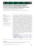
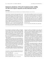
place of tooth # 46 without any restoration (Fig 1).
Detailed dental history revealed that, the mandibular
fixed prosthesis recently droped-off spontaneously with
two implants. According to treatment planning based on
clinical and radiographical examinations, and diagnostic
prosthetic set-up, explantation of the mandibular
implant, yet not mobile was suggested. Prior to implant
removal, the procedure was explained to the patient and a
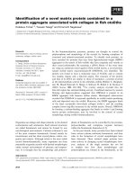
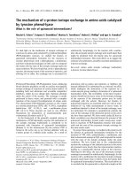
written consent was obtained. Referring to rough and
smooth implant surface border, the mean (mesial and dis-
tal) vertical and horizontal bone loss measured on digi-
tized periapical radiograph using a software for image
analysis (ImageJ 1.34n, NIH, USA) were 7.55 mm and
4.15 mm, respectively (Fig 2). Biological parameters and
assessed mean values at four aspects of the implant during
clinical examination were as follows; modified plaque
index (MPI)
11
: 3, modified bleeding index (MBI) [11]: 3,
the distance between the implant shoulder and the
mucosal margin (DIM): 1.94 mm and the peri-implant
probing depth (PPD): 8.25 mm. No suppuration was
observed around the peri-implant soft tissue.
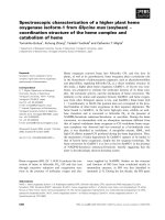
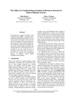
Torque failure of the existing bone-implant interface was
tested using a custom-made strain gauged manual torque
wrench [12]. During application of screwing torque force
via couple of surgical (Institut Straumann) and rachet
adapter (Institut Straumann), the strain-gauge signals
were recorded by a data acquisition system (ESAM Travel-
ler 1, Vishay Micromeasurements Group, Raleigh NC,
U.S.A) and corresponding software (ESAM; ESA Messtech-
nik GmbH, Olching, Germany) at a sample rate of 10 KHz
(Fig 3). Due to lack of interlocking feature between
implant and any compatible article in product range
(Institut Straumann), the torque could not be applied in
counter-clock direction to remove the implant. In essence,
it was beyond the scope of the study to remove the
implant, but to quantify the failure torque of the implant
in bone. The force applied to the handle of manual torque
wrench was transferred as "torque" to the bone-implant
interface along the implant axis via the surgical- and
rachet-adapter. Therefore, the quantification of applied
torque to the bone-implant interface was essential to
implement this information to finite element analysis for
quantification of intraosseous failure torque of the test
implant. In this regard, the strain data of the manual
torque wrench was converted to torque units (N.cm)
according to the procedures explained elsewhere [13,14].
In brief, the strain data were converted to torque units
(N.cm) using the general formula:
Torque = K x
ε
where K is the calibration constant and
ε
is the strain-
gauge reading. Then, torque failure output was imple-
mented in definition of loading conditions of the simula-
tion of in vivo experimental circumstances using finite
element stress analysis.
Head & Face Medicine 2006, 2:36 />Page 3 of 7
(page number not for citation purposes)
Finite element stress analysis
The in vivo experimental circumstances were simulated
using finite element stress analysis to get more informa-
tion about the biomechanical properties of the bone-
implant interface. In this regard, 2-D model of the Ø 3.5
mm × 12 mm ITI
®
hollow screw dental implant (Institut
Straumann) and the solid abutment (Institut Straumann)
were constructed in one-piece using pre-processor,
MSC.Marc Metat 2005 (MSC. Software Corporation, Los
Angeles, CA). Helical continuity in threads of the implant
body was not considered in modelling, but as symmetri-
cal rings [15]. The implant-abutment model was centrally
and vertically positioned into a Ø 20 mm cylindrical
trabecular bone representative with angular peri-implant
bone defect of vertical and horizontal bone loss of 7.5
mm and 4 mm respectively. 3-D finite element (FE)
model conversion was performed by 360
0
axial rotating of
planar model using MSC.Marc Metat 2005 (MSC. Soft-
ware Corporation). A fully-bonded interface was defined
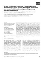
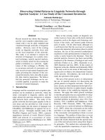
for the implant body in the bone simulant. Eight-node
isoparametric hexahedral elements were used in 3-D FE
model conversion and resulted in 27.300 and 31.500 ele-
ments in implant-abutment and bone, respectively (Fig
4a). The calculated torque unit (N.cm) from on the strain
data obtained during the clinical test that yielded failure
of the bone-implant interface was implemented in defini-
tion of loading conditions in the finite element analysis.
In the definition of loading condition, a centrally located
node (# 17827) on the occlusal surface of the abutment
was selected and retained. All other nodes resting on the
occlusal surface and their degree of freedom (dof) were
connected to centrally retained node using RBE 2 link
(MSC.Software Corporation). Then the rotational torque
force was applied onto the centrally-retained node along
the implant axis (Fig 4b). Rotational torque force that
yield to failure of bone-implant interface was applied on
the occlusal surface of the solid abutment to simulate in
vivo load application. Boundary conditions were estab-
lished by constraining the cylindrical bone circumferen-
tially and from its bottom. The FE analysis solver,
MSC.Marc 2005 (MSC.Software Corporation), was used
for processing the rotational torque force application. All
materials were assumed to be homogenous, isotropic and
linearly elastic with Young's modulus and Poisson's ratio
for implant-abutment complex 110,000 MPa and 0.35,
respectively, and trabecular bone 1850 MPa and 0.3,
respectively. In addition, no further definition was consid-
ered to define bone-implant contact due to lack of vali-
dated data concerning absolute shear bond strength of
bone-implant interface. Scalar results of shear stress in
Panoramic view of both jaws and the implant subjected to torsional failure test in the right premolar regionFigure 1
Panoramic view of both jaws and the implant subjected to torsional failure test in the right premolar region.
Head & Face Medicine 2006, 2:36 />Page 4 of 7
(page number not for citation purposes)
trabecular bone representative were evaluated using post-
processor, MSC.MarcMetat 2005 (MSC. Software Corpo-
ration).
Results
During in vivo torque failure test of bone-implant inter-
face, implant spinning was not evident, but at the
moment of failure, bleeding from the peri-implant sulcus
and partial loss of torque resistance of the implant was
observed. The in vivo torque failure test yielded 5952
μstrains, as determined from the computer software. Con-
version of in vivo strain data to torque units revealed that
the torque failure of the bone-implant interface occurred
at 750 N.cm.
As a sequel of finite element analysis, high shear stress val-
ues were recorded circumferentially at the first intimate
contact of trabecular bone with implant surface. Torsional
shear stresses at first contact with trabecular bone and
consecutive two thread tips in descending order to
implant apical, and were 121 MPa, 109 MPa, and 97 MPa,
respectively (Fig 5a and 5b). Trabecular bone in contact
along with external surface of hollow implant body,
except the bottom regions of threads, experienced lower
shear stress values ranging between 72 – 24 MPa, and dis-
tribution of stresses through trabecular bone were limited
to 250 μm (Fig 5b). Shear stresses at the trabecular bone
interface resting in hollow section of implant body were
ranging between 12 – 0 MPa (Fig 5b). Overall, the stress
distribution in failure test revealed that the highest
stresses were recorded in the occlusal aspect, lower stresses
in the implant body, and very low stresses within the hol-
low part of the implant where, intimate bone contact was
present.
The periapical radiograph of the hollow-screw implant with extensive marginal bone lossFigure 2
The periapical radiograph of the hollow-screw implant with extensive marginal bone loss.
Head & Face Medicine 2006, 2:36 />Page 5 of 7
(page number not for citation purposes)
Discussion
Following intraosseous placement, achievement and
maintenance of direct bone-implant contact is of utmost
importance for optimum long-term functioning of oral
implants. One of the major concerns regarding mechani-
cal integration of implants is the interfacial strength
between the bone and the implant. Therefore, evaluation
of shear strength of bone-implant interface with pushout
and pullout experiments are required to test mechanical
competence of orthopedic and oral implants. In essence,
the rationale behind the common use of uniaxial testing
is the relative simplicity in the experimental procedures
[16]. If the shear strength of bone-implant interface is
being tested, outcomes of torque failure tests are more
dependable, when moment forces in oral function are
considered. In this regard, ex vivo torque failure studies to
test bone-implant interface are abundant [17-19]. In addi-
tion, nominal shear strength of bone-implant interface
also has been calculated mathematically in some studies
[20-22]. Owing to different experimental circumstances
including test sites, species and material configuration,
the consistency of these techniques with actual clinical
conditions are questionable. Because of ethical considera-
tions, available human torque failure data are either lim-
ited to a study [10] carried on transitional implants or a
case report [23] of 2 non-loaded conventional implants.
Unlike previous studies, in the present biomechanical
study, shear stress state of bone-implant interface was
evaluated using FE analysis. As creating a consistency
between models and biological data is the main objectives
in biomechanical studies, the applied load definition was
based on clinical torque failure test of the simulated
implant and peri-implant conditions. Biological condi-
tions and mechanical test procedure might affect the in
vivo data. Advanced peri-implantitis place an argument
The manual torque wrench with adapter connected to implantFigure 3
The manual torque wrench with adapter connected to
implant.
a) The finite element model of the implant. Note that, approximately 30–35% bone loss is present around the implant, although the hollow part is totally filled with bone. b) The centrally-retained nod and the nodes attached to this node is presented in red color. The rotational force is applied at this node, which coincides with the implant- or the y-axis (purple)Figure 4
a) The finite element model of the implant. Note that, approximately 30–35% bone loss is present around the implant, although
the hollow part is totally filled with bone. b) The centrally-retained nod and the nodes attached to this node is presented in red
color. The rotational force is applied at this node, which coincides with the implant- or the y-axis (purple)
Head & Face Medicine 2006, 2:36 />Page 6 of 7
(page number not for citation purposes)
regarding validity of osseointegration. In addition to lack
of peri-implant radiolucency, acute infection with suppu-
ration and mobility was not associated clinically for the
implant tested. Therefore, the clinical/radiologic status of
the implant, as suggested within a recent consensus report
[24], rendered the existence of osseointegration for accu-
rate torque failure measurement. In the present study, the
torsional load was applied in clock-wise direction for the
measurement of interfacial bond failure. Perception of
"start to debonding" was referred to initial torque failure
of bone-implant interface during experiment. In other
words, peak torque output that likely yielded complete
loosening of implant in bone was not considered in this
study, because the validity of the output would have been
speculative due to probable apical bone resistance to
screwing of the implant. In the present finite element
analysis, a linear solution was performed, the contact
between the implant-abutment interface, and the
implant-bone interface, namely, contact analysis, was not
undertaken. During clinic test, because the force was
applied in the clock-wise direction and abutment loosen-
ing did not occur, a linear solution did not influence the
outcome of the study. Taking the limited bone support of
the implant into account, it would be very useful to
"define" the "contact" in detail between bone and the
implant and the properties of bonding, if possible. In
essence, the "core" this study was based on this rationale,
as there is no information dealing with the magnitude and
nature of contact bond between an implant with bone so
far. In the present study, the authors assume that there has
not been any limitation of quantification of failure torque
in the clinic test, but the implementation of this informa-
tion to a finite element model with a defined "bond" at
the contact surfaces could be very useful. The information
obtained in the present study could, therefore, be used in
future studies to define "bond" in contact analysis of
bone-implant interface.
In the present study, evaluation of the shear stress state of
peri-implant bone revealed that trabecular bone within
hollow part of the implant body did not contribute to
interfacial shear strength. This finding is very important
clinically, as the one of the rationale behind fabricating
such hollow-screw implants was to increase bone-implant
contact and improve the biomechanical performance of
these implants. The very low magnitude stresses within
the hollow part, in comparison with the higher stresses in
the outer aspect demonstrate that it is the surface of the
implant, particularly the marginal bone region that bears
the failure load. Indeed, highest shear stress, which likely
indicates the location of "start to debonding", was
observed at the first intimate contact of trabecular with the
implant surface. This, in part, may also explain why time-
dependent bone resorption takes in the marginal bone
region, although higher loads and stresses occur in the
apical part of loaded implants. It is also very interesting to
note that the screw threads resist torsional load to a great
extent, as low magnitude stresses were observed on the
implant body between the threads. This also implies that
the design of threads, particularly at the collar region of
implants is crucial [25], should decrease peak interfacial
shear stresses, and provide optimum distribution of
stresses in order to decrease the risk of microdamage in
bone during clinical loading. Because a very high strain
Peak interfacial shear stresses around the implant demonstrating high shear stresses at the junction of bone implant contact and very low stresses within the hollow partFigure 5
Peak interfacial shear stresses around the implant demonstrating high shear stresses at the junction of bone implant contact
and very low stresses within the hollow part.
Publish with BioMed Central and every
scientist can read your work free of charge
"BioMed Central will be the most significant development for
disseminating the results of biomedical research in our lifetime."
Sir Paul Nurse, Cancer Research UK
Your research papers will be:
available free of charge to the entire biomedical community
peer reviewed and published immediately upon acceptance
cited in PubMed and archived on PubMed Central
yours — you keep the copyright
Submit your manuscript here:
/>BioMedcentral
Head & Face Medicine 2006, 2:36 />Page 7 of 7
(page number not for citation purposes)
gradient was needed to fail the implant having approxi-
mately 30–35% bone contact, it is tempting to speculate
that an osseointegrated implant may present more that
three-fold increase in torsional strength than achieved in
the present study (121 MPa). Yet, further studies are
required to substantiate our claims.
Competing interests
The author(s) declare that they have no competing inter-
ests.
References
1. Albrektsson T, Zarb G, Worthington P, Eriksson AR: The long-
term efficacy of currently used dental implants. A review and
proposed criteria of success. Int Oral Maxillofac Implants 1986,
1:11-25.
2. Buser D, Weber HP, Lang NP: Tissue integration of non-sub-
merged implants. 1-year results of a prospective study with
100 ITI hollow-cylinder and hollow-screw implants. Clin Oral
Implants Res 1990, 1:33-40.
3. Karoussis IK, Brägger U, Salvi GE, Burgin W, Lang NP: Effect of
implant design on survival and success rates of titanium oral
implants: a 10-year prospective cohort study of the ITI Den-
tal Implant System. Clin Oral Implants Res 2004, 15:8-17.
4. Mombelli A, Lang NP: The diognosis and treatment of peri-
implantitis. Periodontol 2000 1998, 17:63-76.
5. Mombelli A: Prevention and therapy of peri-implant infec-
tions. In Proceedings of the 3rd European Workshop on Periodontology.
Implant Dentistry Edited by: Lang NP, Karring T, Lindhe J. Berlin: Quin-
tessenz; 1999:281-303.
6. Lang NP, Wilson TG, Corbet EF: Biological complications with
dental implants: their prevention, diagnosis and treatment.
Clin Oral Implants Res 2000, 11:146-155.
7. Baron M, Haas R, Dörtbudak O, Watzek G: Experimentally
induced peri-implantitis: A review of different treatment
methods. Int Oral Maxillofac Implants 2000, 15:533-544.
8. Brånemark PI, Zarb GA, Albrektsson T: Tissue-Integrated Prostheses:
Osseointegration in Clinical Dentistry Chicago: Quintessence;
1985:175-186.
9. Buser D, Nydegger T, Oxland T, Cochran DL, Schenk RK, Hirt HP,
Snetivy D, Nolte LP: Interface shear strength of titanium
implants with a sandblasted and acid etched surface: A bio-
mechanical study in the maxilla of miniature pigs. J Biomed
Mater Res 1999, 45:75-83.
10. Simon H, Caputo AA: Removal torque of immediately loaded
transitional endosseous implants in human subjects. Int J Oral
Maxillofac Implants 2002, 17:839-45.
11. Mombelli A, van Oosten MAC, Schürch E, Lang NP: The microbiota
associated with successful or failing osseointegrated tita-
nium implants. Oral Microbiol Immunol 1987,
2:145-151.
12. Cehreli MC, Akca K, Tonuk E: Accuracy of a manual torque
application device for morse-taper implants: a technical
note. Int J Oral Maxillofac Implants 2004, 19:743-748.
13. Cehreli MC, Akca K, Sahin S, Iplikcioğlu H: Dynamic fatigue resist-
ance of ımplant-abutment junction in an ınternally-notched
morse taper oral ımplant: ınfluence of abutment design. Clin
Oral Implants Res 2004, 5:459-465.
14. Akkocaoglu M, Uysal S, Tekdemir I, Akca K, Cehreli MC: Implant
design and intraosseous stability of immediately-placed
implants: A human cadaver study. Clin Oral Implants Res 2005,
16:202-209.
15. Akca K, Cehreli MC, Iplikcioğlu H: Evaluation of the mechanical
characteristics of the implant-abutment complex of a
reduced-diameter morse-taper implant. A nonlinear finite
element stress analysis. Clin Oral Implants Res 2003, 14:444-455.
16. Berzins A, Summer DR: Implant pushout and pullout tests. In
Mechanical testing of bone and the bone-implant interface Edited by: An
YH, Draughn RA. Florida: CRP Press LLC; 2000:463-467.
17. Buser D, Nydegger T, Hirt HP, Cochran DL, Nolte LP: Removal
torque values of titanium implants in the maxilla of minia-
ture pigs. Int J Oral Maxillofac Implants 1998, 13:611-619.
18. Li D, Ferguson SJ, Beutler T, Cochran DL, Sittig C, Hirt HP, Buser D:
Biomechanical comparison of the sandblasted and acid-
etched and the machined and acid-etched titanium surface
for dental implants. J Biomed Mater Res 2002, 60:325-32.
19. Bernard J-P, Szmukler-Moncler S, Pessotto S, Vazquez L, Belser UC:
The anchorage of Brånemark and ITI implants of different
lengths. I. An experimental study in the canine mandible. Clin
Oral Implants Res 2003, 14:593-600.
20. Stenport VF, Johansson CB, Sawase T, Yamasaki Y, Oida S: FGF-4
and titanium implants: a pilot study in rabbit bone. Clin Oral
Implants Res 2003, 14:363-368.
21. Hayashi K, Inadome T, Tsumura H, Nakashima Y, Sugioka Y: Effect
of surface roughness of hydroxyapatite-coated titanium on
the bone-implant interface shear strength. Biomaterials 1994,
15:1187-91.
22. Wang BC, Lee TM, Chang E, Yang CY: The shear strength and the
failure mode of plasma-sprayed hydroxyapatite coating to
bone: the effect of coating thickness. J Biomed Mater Res 1993,
27:1315-27.
23. Simon H, Caputo AA: Removal torque of immediately loaded
transitional endosseous implants in human subjects. Int J Oral
Maxillofac Implants 2002, 17:839-45.
24. Sullivan DY, Sherwood RL, Collins TA, Krogh PH: The reverse-
torque test: A clinical report. Int J Oral Maxillofac Implants 1996,
11:179-185.
25. Lang NP, Berglundh T, Heitz-Mayfield LJ, Pjetursson BE, Salvi GE, Sanz
M: Consensus statements and recommended clinical proce-
dures regarding implant survival and complications. Int J Oral
Maxillofac Implants 2004, 19:150-4.