Recycling of Plastic Materials Part 2 potx
Bạn đang xem bản rút gọn của tài liệu. Xem và tải ngay bản đầy đủ của tài liệu tại đây (481.25 KB, 17 trang )
MONOMER RECOVERY
Although monomer recovery is the oldest recycling method and can be used to
recover PET-waste having a high degree of impurity, it is regrettable that it is
not the most economical method. The earliest methods of PET synthesizing
were based preferentially on the use of dimethyl terephthalate (DMT), which
could be better purified than terephthalic acid (TPA), therefore methanolysis is
discussed before hydrolysis. The chemical principles of both processes are al-
ready given in Figure 4.
Methanolysis of PET-waste
The waste is treated with methanol (in a ratio 1/2 to 1/10), usually under pres-
sure at high temperatures (160-310
o
C) in the presence of transesterificationand
(or) depolymerization catalysts.
17
Once the reaction is completed, DMT is
recrystallised from the EG-methanol mother liquor, and distilled to obtain poly-
merization-grade DMT. Also EGandmethanolare purified by distillation.East-
man Kodak has been using such a process for recycling of X-ray films for 25
years, and itis still improving theprocess,
18
e.g., by usingsuperheated methanol
vapor, to allow the use of ever more impure PET-waste. Important factors which
have to be dealt with in this process are avoiding coloration and keeping down
the formation of ether-glycols.
Hydrolysis of PET-waste
19
Although aromatic polyesters are rather resistant to water under atmospheric
conditions, compared with other polymers, they can be completely hydrolyzed
by water at higher temperatures (and) under pressure. For practical purposes,
however, particularly to speed up the process, use has to be made of catalysts.
Acidic as well as alkaline catalysts have been studied and worked out in prac-
tice.
Figure 5 gives a flow chart of both processes. While both systems are com-
pletely realistic, their usefulness under practical production conditions remains
controversial. As far as acid hydrolysis is concerned, the large acid consumption
and the rigorous requirements of corrosion resistance of the equipment make
profitability questionable. In addition, the simultaneous (with TPA) regenera-
tion of ethylene glycol is difficult, ecologically undesirable (requiring the use of
organic halogenated solvents), and not economical. Concerning alkaline hydro-
lysis, the profitabilityis strongly determined bythe necessity of expensivefiltra-
8 PET Film Recycling
W. De Winter 9
Figure 5. Flow chart of acid- and base-catalyzed PET degradation.
tion and precipitation steps. To our knowledge, recycling of PET-waste by
hydrolysis is not practiced on a production scale at present. This situation even
persists in spite of the fact that the majority of newer industrial PET-synthesis
plants are based on the TPA-process rather than on the DMT-process.
20
INCINERATION
Another approach which can be used to recycle plastics, particularly when
they contain alarge amount of impuritiesand other combustible solids(if such is
a case, it is important to keep them away from landfills), is more recently called
“quaternary recycling”, and consists of the energy recovery from the wastes by
burning.
21
Research along this line has been performed, particularly in Europe
and Japan, since the early 1960s. Strong emphasis has been laid on an optimiza-
tion of incinerators with regard to higher temperature of their operation and re-
duction of the level of air pollution.
PET has a calorific value of ca. 30.2 MJ/kg, which is about equivalent to that of
coal. It is thus ideally suited for the incineration process. The combustion of
plastics, however, requires 3 to 5 times more oxygen than for conventional incin-
eration, produces more soot, develops more excessive heat, and incineration
equipment had to be adapted in order to cope with these problems.
Several processes have been worked out to overcome these technological draw-
backs.
22-27
Examples include Leidner’s continuous rotary-kiln process, Baliko’s
process for glass-reinforcedPET, Crown Zellerbach Corporation’scombined sys-
tem for wood fibre and PET to provide steam to power equipment, and ETH-Zu-
rich’s fluidized bed system for pyrolysis, especially of photographic film, i.e., in
combination with silver recovery. The latter system raises the additional prob-
lem of the formation of toxic halogenated compounds, stemming from the pres-
ence of silver halides.
Typical operation conditions take place at temperatures around 700
o
C. At
lower temperatures, waxy side-products are formed, leading to clogging. At
higher temperatures, in turn, the amount of the desirable fraction of
mononuclear aromatics decreases. A representative sample, pyrolysed under
optimized conditions, yields, in addition to water and carbon, aromatics like
benzene and toluene, and a variety of carbon-hydrogen and carbon-oxygen
gases. Studies have been performed
1
to avoid formation of dioxines and disposal
of residual ashes containing heavy metals and other stabilizers.
10 PET Film Recycling
be resolved; however, quite a few residual hurdles will have to be taken
25
before
an economically feasible and ecologically accepted industrial technical process
will be available.
BIO- AND PHOTO-DEGRADATION
Although there certainly has never been a great incentive for making unstable
polymers, the idea of making photo- or bio-degradable polymers has long ex-
isted,
28,29
and quite a bit of effort has gone into research along these lines. For
such a process, of course, limitations with regard to the percentage of allowable
impurities do not exist.
Photodegradation
Special photodegradable polymers
30
were synthesized for the purpose of hav-
ing them destroyed after use(e.g., in a landfill). Another approach was theincor-
poration of suitable groups (e.g., carbonyl) in the polymer backbone in order to
make polymer photodegradable by sunlight or UV (see Figure 6). A problem
arises due to the fact that light exposure conditions on a landfill cannot be regu-
lated. The maindifficulty, however, seems tobe practically insurmountable: it is
W. De Winter 11
Figure 6. Photodegradable monomers and polymers.
31
At present it seems that most problems arising during incineration of PET can
hardly possible to combine rapid degradation upon exposure to light in a landfill
after use with a good light-stability of the film during service. This contradictio
in terminis is probably the reason why this method never really caught on.
29
An-
other problem is a combination ofdesired properties with favorableeconomics.
Biodegradation
The main difference between biodegradation and photodegradation lies in the
possibility to create in a landfill an environment completely different from that
encountered under normal storage conditions; e.g., microorganisms which can
destroy plastic films may be added to a landfill.
In spite of the fact that substantial research time was spent on studies in this
field, it is claimed
32
that surprisingly little is understood about the molecu-
lar-level interaction between polymers and microorganisms. This can be ex-
plained by a poorly defined environment (in a landfill), and by a large number of
complex parameters involved in the process: methods of evaluation based solely
on changes in physical properties are thus unsuitable for forming conclusions,
similar to the evaluations based only on biogas production. Specifically for poly-
esters, however, a number ofinteresting data are available. Esterases (ester-hy-
drolyzing enzymes) and also some microorganisms are known to biodegrade
polyesters at a reaction rate depending upon the polyester structure.
29,33
While
many aliphatic polyesters, specifically poly(hydroxy fatty acids) - e.g., the
BIOPOL
34-36
packaging material commercialized by ICI - are suited for
biodegradation, the aromatic polyesters (e.g., PET) do not possess this prop-
erty.
32,37-39
Another approach consists of mixing small amounts of biodegradable poly-
mers, e.g., polysaccharides,with a regular polymer(e.g., a polyolefin), inorder to
make the end-product destroyable as well. Examples of polysaccharides/poly-
ethylene have been commercialized.
38
Mixtures of starch with other polymers,
40
12 PET Film Recycling
including PET, have been studied,
34
but no commercialization of the latter mix-
ture is known so far. The fact, however, that the starch additive is only needed in
small amounts, which hardly alters the properties of an original polymer, might
show some promise for future applications. One has to realize, however, that the
thermal stability of starch derivatives above 230
o
C is limited, whereas the
PET-film extrusion temperature is in the range of 280
o
C. There also remain
some controversies about the completeness of the degradation of polymer/starch
mixtures.
Although the development of biodegradable plastics is still in progress, it is be-
coming evident that theenormous market potential, forecast some yearsago, re-
quires a real breakthrough in order to be attained.
41,42
The main reason for this
setback is probably the fact that organic polymers do not biodegrade fast
enough.
43,44
CONCLUSIVE REMARKS
• From the data presented in this overview, it seems obvious that there ex-
ists a clear hierarchy in PET-film recycling technologies. The most impor-
tant criteria of classification are, first of all, the degree of “purity” of
PET-scrap to be handled, and secondly, the economics of the process.
• For the cleanest PET grade, the most economical process, i.e., direct re-use
in extrusion, is self-explanatory.
• For less clean PETsamples, it is still possible tore-use them after the modi-
fication step (partial degradation, e.g., by glycolysis) at a reasonably low
price.
• More contaminated PET-film waste must be degraded into the starting
monomers, which can be separated and re-polymerized afterwards, of
course, at a higher cost. At present, only the methanolysis process is ex-
ploited industrially, as opposed to hydrolysis processes, which are kept in
reserve.
• Finally, the most heavily contaminated PET-shreds have to beincinerated.
Here, however, economics may not be favorable enough for industrial de-
velopment. As an alternative, those PET-shreds are brought to a landfill.
Perhaps in future more attention will be given to modification of PET-films
in such a way that they may become biodegradable, if the process can be ac-
celerated or if a real breakthrough becomes available.
W. De Winter 13
REFERENCES
1 F. P. Boettcher, ACS Polymer Preprints, 32 (2), 114 (1991).
2. W. De Winter, Die Makromol. Chem., Macromolecular Symposia No. 57, 253 (1992).
3. Anon., Plastics Bulletin, 174, 6 (Jan-1992).
4. N. Basta et al., Chem. Eng., 97, 37 (Nov-1990).
5. Brit. Pat. 1.476.539 (1977) to Barber-Colman Co.
6. Anon., Manufacturing Chemist, 66, (Mar-1987).
7. L. Hellemans, R. De Saedeleer, and J. Verheijen, US Pat. 4,008,048 (1977)
to Agfa-Gevaert.
L. Jeurissen and F. De Smedt, Brit. Pat. 1,486,409 (1977) to Agfa-Gevaert.
J. Tempels, Brit. Pat. 1,432,776 (1976) to Agfa-Gevaert.
8. W. Fisher, US Pat. 2,933,476 (1960) to du Pont.
9. J. Burke, in Plastics Recycling as a Future Business Opportunity, Technomic
Publishing Co, Pennsylvania, USA, (1986).
10. K. Datye, H. Raje, and N. Sharma, Resources and Conservation, 11, 117 (1984).
11. D. Gintis, Die Makromol.Chem., Macromolecular Symposia, 57, 185 (1992).
12. R. Richard et al, ACS Polymer Preprints, 32 (2), 144 (1991).
13. A. Petrov and E. Aizenshtein, Khim. Volokna, 21 (4), 16 (1979).
14. US Pat. 3,884,850 to Fiber Ind.
15. Anon., Mod. Plast. Int., 20, 6 (1990).
16. A. M. Thayer, Chem. Eng. News, (Jan. 13, 1989).
17. Brit. Pat. 784,248 (1957) to du Pont.
18. Anon., Eur. Chem. News, 30 (Oct. 28, 1991).
19. H. Ludewig, Polyester Fibers, Chemistry and Technology, Wiley Int. Publ., 1971.
20. H. Schumann, Chemiefasern Textil, 11, 1058 (1990).
U. Thiele, Kunststoffe, 79 (11), 1192 (1989).
21. T. Randall Curlee, The Economic Feasibility of Recycling, Praeger Publishers,
New York, 1986.
22. Leidner, Polymer Plastics Techn. & Eng., 10 (2), 199 (1978).
23. S. Baliko, Energiagazdalkodos, 28 (11), 496 (1987).
24. D. Vaughan, M. Anastos, and H. Krause, Rpt. Battelle Columbus Lab.,
EPA-670/2-74-083, (Dec-1974).
25. R. Hagenbucher et al, Kunststoffe, 80 (4), 535 (1990).
26. K. Niemann and U. Braun, Plastverarbeiter, 43 (1), 92 (1992).
27. W. Kaminsky et al., Chem. Ing. Techn., 57 (9), 778 (1985).
28. Guillet, Chem. Eng. News, 48, 61 (May 11, 1970).
29. F. Rodriguez, Chem. Techn., 409, (Jul-1971).
30. G. Smets, Chem. Magazine, 481, (Sep-1989).
31. Brit. Pat. 1,128,793 (1968) to E. Kodak.
32. G. Loomis et al., ACS-Polymer Preprints, 32 (2), 127 (1991).
33. R. Klausmeier, Soc. Chem. Ind., London, Monogr., 23, 232 (1966).
34. Anon., Neue Verpackung, 1, 50 (1991).
35. J. Emsley, New Scientist, 50, 1 (Oct. 19, 1991).
14 PET Film Recycling
36. A. Steinbuchel, Nachr. Chem. Techn. Lab., 39 (10), 1112 (1991).
37. P. Klemchuk, Mod. Plastics Int., 82, (Sep-1989).
38. J. Evans and S. Sikdar, Chemtech, 38, (Jan-1990).
39. K. Joris and E. Vandamme, Technivisie, 179, 5, (1992).
40. R. Narayan, Kunststoffe, 79, 1022 (1989).
41. N. Holy, Chemtech, 26, (Jan-1991).
42. A. Calders, Technivisie, 156, 8 (Nov-1990).
43. Anon., Mod. Plast., 20 (1), 72 (1990).
44. H. Pearce, Scient. European, 14, (Dec-1990).
W. De Winter 15
The Importance and Practicability of Co-Injected,
Recycled Poly(ethylene terephthalate)/Virgin
Poly(ethylene terephthalate) Containers
Eberhard H. Neumann
Nissei ASB GmbH, Mündelheimer Weg 58, D-4000 Düsseldorf 30, Germany
INTRODUCTION
In several European countries, packaging items, whether they are made of
plastic, paper, metal, etc., are under governmental and public pressure.
Well-known are:
• actions to ban all plastic bags in one southern European country
• the boycott of plastic packages in certain alpine villages
• Denmark’s ban of metal cans for beverages
• Switzerland’s removal of all PVC-packages
• Germany’s set-up of a mandatory deposit on beverage bottles made of plas-
tic and limiting sales on non-refillables.
The list of restrictions on packages and their markets in Europe could be end-
less. Increasing environmental concerns, overloaded landfills and inadequately
equipped or even not existing garbage incineration units are calling for solu-
tions.
Out of many proposals two solutions are always highlighted in public discus-
sions:
• refillable and returnable packaging articles to reduce the amount of house-
hold refuse
• recycling of post-consumer packages.
Regarding recycling systems for post-consumer plastic bottles, companies
have already installed plants in North America which are profitable operations.
However, these systems are leading to a converting technology which trans-
forms discarded plastics into a range of second-use commodities, as well as low
E. H. Neumann 17
cost base specialties.
This paper is intended to show a technology, whereby discarded plastic bottles
for beverages, food and household items - being post-consumer ware - can be
used to manufacture the same range of packaging articles (bottles) for which
they were originally made. Additional goal is to assure the highest level of safety
offered by the original products made from virgin plastic.
BASIC TECHNOLOGY
Injection molding technologyinvolves the injection ofmolten plastic into one or
several cavities via a hot-runner system (melt-channel distribution system) and
rapid cooling of a preform to a low temperature. At this point the freshly manu-
factured article can be ejected from the cavity. In multilayer technology, more
than one plastic resin is injected into the cavity.
The different resins are molten in separate injection units, conveyed in sepa-
rate hot-runner channels, under pressure and high temperature, to an injection
nozzle, which is the gate area for the molten plastic, into the cavity.
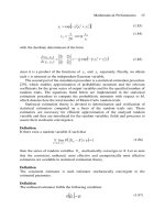
This injection nozzle consists of an outside and an inside tube. Both plastic
streams are brought together after beingreleased from the nozzle and they bond
together because of a high pressure (up to 300 bar) and a high melting tempera-
ture (see Figure 1).
MANUFACTURING PROCESS
OF MULTILAYER BOTTLES CONTAINING REGRIND
For the process, a machine used had one injection unit for virgin PET and an-
other injection unit for reground PET flakes. The individual steps of the process
are described below.
Drying of PET resin and PET flakes (Figure 2)
The drying of a virgin PET resin and reground PET flakes at temperature lev-
els of 160-180
o
C to below 0.005% moisture content is essential for the production
of amorphous multilayer polyester bottles. Polyester is an effective desiccant.
The water absorption depends on a relative humidity, residence time, tempera-
ture, and dimension of the flakes.
When flakes containing moisture are heated up to the melting temperature,
hydrolytic degradation occurs lowering a viscosity of the melt that results in en-
hanced ability of preforms/bottles to crystallize (milky appearance).
18 PET Co-injection Molding
The dryer and the hopper for the virgin PET chips are of standard design. The
unit for the reground PET flakes is of almost the same design but it needs an in-
ternal agitator (propeller) whichprevents the amorphous PET flakes fromstick-
ing together. To be exact this is not a problem inherent in the highly stretched
bottle sidewalls (these flakes do not show this property). The problem is rather
that ground-up flakes come from non-stretched portions of PET bottles, i.e. the
neck or bottom.
Above the glass transition temperature (74
o
C) the flakes will stick together be-
cause of adhesional forces. It is therefore necessary to reduce a contact time be-
tween the individual flakes and keep them constantly moving in a hopper to
avoid the above mentioned sticking process and bridge building in the hopper.
This is carried out by the agitator installed inside the hopper. The flakes coming
E. H. Neumann 19
Figure 1. A diagram of an injection molding equipment.
from less stretched bottle regions, i.e. the neck and bottom recrystallize during
the drying process. Crystallized flakes will not stick together.
The dried reground PET flakes are fed via a feeding-extruder into the throat of
the satellite injection (2nd and 3rd)unit of the multilayersingle stage machine.
An extruder feeder is necessary because PET flakes are bulky and cause prob-
lems when they are fed by gravity into the screw of the injection unit.
Co-injection molding of virgin and reground PET flakes
The virgin PET as well as the reground PET flakes are melted inside the sepa-
rate injection units bymeans of external electrical heating ofthe injection barrel
and the applied shear forces of the screw, driven by a hydraulic motor (see Fig-
ure 1).
20 PET Co-injection Molding
Figure 2. Close-loop drying system for PET regrind
The PET melt, either coming from virgin PET or from PET flakes, is accumu-
lated in the head-space of the barrel head and released into the hot runner
(melt-channel system) under high injection pressure and at a certain
melt-stream velocity. The melt is kept in a molten stage, inside the hot runner
system because of the electric heating systems. The two melt-streams (virgin
and reground PET) are kept, up to the injection nozzle, in separate hot runner
channels.
At the end of the hot-runner channels, at the gate area of the injection cavity,
two nozzles are installed like a double tube or as one tube with a second smaller
tube inside it.
A portion of a virgin PET melt, forming the outside layers, is first injected into
the preform cavity. Under controlled pressure another melt-portion coming
from the reground PET is injected into the core of the virgin PET melt cake. Sub-
sequently both injection units inject further melt (from virgin and reground
PET) simultaneously during the cavity fill process. This three phase filling pro-
cess results in a preform made from the following layers: inside/middle/outside
(virgin PET/regrind PET/virgin PET).
During the cavity filling process, the layers do not mix together because the in-
dividual melt-layers have a high melt viscosity and are not subjected to a turbu-
lent flow.
The adhesion between the individual preform layers is as good as if the layers
were welded together and formed monolayer preform (made out of one melt
stream).
Conditioning and stretch-blow-molding
Thermal conditioning is the next step of the multilayer preform production.
The purpose of thermal conditioning of a given preform is to provide the neces-
sary temperature distribution in a preform. After leaving the injection mold and
undergoing cooling process, the preform has a cross-sectional temperature dis-
tribution of an upside-down U-shape, which means that the middle of the pre-
form wall shows higher temperatures than the two outside skin-layers.
Since PET stretch properties are influenced by the temperature level above
the glass transition point of PET, the preform requires more even temperature
distribution, otherwise the middle layer will stretch at a different rate from the
skin-layers. Thermal conditioning can be carried out by allowing the preform to
equilibrate before stretch-blow-molding or by applying thermal energy from the
E. H. Neumann 21
outside by moving the heater-pots around the preform and/or by allowing a
heated core rod to plunge into the center of the preform, thus influencing the
thermal profile of a preform wall from the inside.
After thermal conditioning is accomplished, thepreform is transferred into the
blow mold of the stretch-blow-molding station. Here the preform is axially
stretched by using a stretch rod and circumferentially inflated by air pressure,
to match the shape of the blow mold. The final bottle is cooled down due to the
contact heat losses on the metal surface of the blow mold.
The stretch-blow-molding process leads to a biaxial orientation of the
macromolecules resulting in better mechanical properties and lowering the gas
permeation of bottles.
Double-layer preforms
The injection molding technique using double layer technology is an alterna-
tive method. By this method the first preform is made of a thin layer of virgin
PET. In the next step, melt from reground PET flakes is injected into the exte-
rior of the preform layer made of virgin PET. Such technologyrequires two injec-
tion preform molds and subsequently a five station machine, compared with a
standard machine which has four.
TRIALS OF CO-INJECTING VIRGIN PET AND REGROUND PET
FLAKES
The following trials were carried out at NISSEI ASB headquarters in Komoro,
Japan.
Quality of the raw materials
Virgin PET had an intrinsic viscosity of 0.78 dl/g and was crystallized and solid
state-polycondensed (upgraded) by the chemical manufacturer. PET reground
flakes came from an unknown PET source. The flakes consisted of 100% PET be-
fore the reground bottle flakes went through a separation and clean-up process.
The flakes were not regranulated since this step involves separate machinery
and would add to the cost of the reground polymer material. The intrinsic viscos-
ity was 0.03 to 0.05 dl/g lower compared to that of virgin PET. Such difference is
negligible. Only extreme variation in viscosities of melt-layers can lead to pro-
cessing problems. The size of flakes was in general between 9 and 49 mm
2
.
22 PET Co-injection Molding
E. H. Neumann 23
Figure 3. Bottle shape and the thickness of layers.
The trial processing
For the trial approach, a NISSEI ASB-250 T-Series machine (multilayer type)
was used. The processing parameters, as chosen, were within standard set-ups.
The bottle shape for these trialsand its layer distributionareshown in Figure 3.
Trial results
The manufactured bottles were of a high quality. When supplied with a clean
regrind, the transparency was similar to that of comparable monolayer bottles.
Physical and mechanical properties of the multilayer bottles were the same as
the monolayer types (creep under CO
2
pressure, top-load, impact strength).
Standard treatment like drop testing and bottle squeezing did not result in
delamination of the layer structure. In conclusion, all trialresults indicated that
multilayer bottles had comparable properties to those having monolayer struc-
tures.
COST SAVINGS
The cost saving in PET bottle production by co-injection technology, using an
inexpensive polymer layer, is about 20% as calculated in Table 1. The calcula-
tion includes a higher investment cost of machinery for the co-injection technol-
ogy as compared to the monolayer bottle production which employs less
expensive monolayer machinery.
CONTAMINATION ASPECTS
Several aspects regarding potential contamination of the middle layer made
from the post-consumer PET bottle flakes, are discussed below.
Bacteriological contamination
The majority of micro-organisms found on PET bottle surfaces is washed away
during the cleaning process of the post-consumer reground PET flakes. The re-
maining minor amounts do not survive the drying and processing temperature
in the injection molding unit, which reaches 180 and 270
o
C, respectively.
Contamination by foreign substances
There is a possibility that PET bottles are used for storage of substances which
can cause danger to human health. Analysis was conducted, using health-en-
dangering substances, to evaluate the effect of PET surfaces exposure. The mi-
gration and leaching of thesesubstances were examined. It was found that, even
24 PET Co-injection Molding
with strong toxic substances, like pesticides, the migration into PET surfaces is
extremely low and furthermore, the re-migration rate (possible leaching of sub-
stances) is so low (a small fraction of the migration rate) that the values were
well below the average daily intake specified by FDA.
E. H. Neumann 25
Table 1
Manufacturing cost comparison of PET/PET-regrind bottles
Container: round bottle, free-standing Material: PET/regrind Content: 1000 ml
Equipment/operation Output Resin price (DM/kg)
Bottle weight
(g)
Price per bot-
tle (DM)
NISSEI ASB-650 N PET 8
cavities (monolayer)
1,371
Virgin-injec-
tion-stretch-blow PET
3.20
35 0.1767
NISSEI ASB-650 NT 8
cavities (multilayer)
1,371
Regrind PET (bottle
flakes) 1.30
35 0.1435-0.1501
Machinery type NISSEI ASB
Unit DM/h 650 N (monolayer M/C)
650 NT (multilayer
M/C)
650 NT (multilayer
M/C)
1. Equipment cost amortization 48.57 100% 62.17 60% 70% PET-regrind
2. Interest 8% p.a.
3.89 virgin PET
4.97
PET-regrind
30% virgin PET
3. Energy consumption 0.15 DM/kWh (main equipment)
11.55 12.30 40%
4. Energy consumption 0.15 DM/kWh (auxiliary equip-
ment)
3.75 3.75 virgin PET
5. Rent for space 8 DM/m
2 per month: 500 h 0.28 0.35
6. Labour (1/3 operator) 33 DM/h 11.00 11.00
7. Maintenance 20% of machine price 9.71 12.43
8. Entire cost per hour 88.75 106.97 106.97
9. Cost and output per hour (production cost) = DM/PC 0.0647 0.0780 0.0780
10. Total resin cost including scrap = DM/PC 0.112 0.0721 0.0655