Plastics Engineered Product Design Part 2 ppsx
Bạn đang xem bản rút gọn của tài liệu. Xem và tải ngay bản đầy đủ của tài liệu tại đây (1.01 MB, 40 trang )
20
Plastics Engineered Product Design
of molding BMCs is compression. They can also be injection molded in
much the same way as other RTS compounds using ram, ram-screw,
and, for certain BMC mixes, conventional reciprocating screw.
Commodity
8
Engineering Plastics
About
9Owt%
of plastics can be classified as commodity plastics (CPs),
the others being engineering plastics (EPs). The EPs such as
polycarbonate
(PC)
representing at least
SOwt%
of
all
EPs,
nylon,
acetal, etc. are characterized by improved performance in higher
mechanical properties, better heat resistance, and
so
forth (Table
1.4).
Tabie
1.4
Thermoplastic engineering behaviors
Crys
tulline
Acetol
Best property balance
Stiffest unreinforced thermoplastic
Low friction
High melting point
High elongation
Nylon
Amorphous
Polycurbona te
Good impact resistance
Transparent
Good electrical properties
Modified
PPO
Hydrolytic stability
Good
impact resistance
Toughest thermoplastic Good electrical properties
Absorbs moisture
High stiffness
Lowest creep
Excellent electrical properties
The EPs demand a higher price. About a half century ago the price per
pound was at
20G;
at the turn of the century it went
to
$1.00,
and now
higher. When CPs with certain reinforcements and/or alloys with other
plastics are prepared they become
EPs.
Many
TSs
and
RPs
are
EPs.
Polyester (glass-rein forced)
Elastomers/Rubbers
In the past rubber meant a natural thermoset elastomeric (TSE)
material obtained fiom a rubber tree, hevea braziliensis. The term
elastomer developed with the advent of rubber-like synthetic materials.
Elastomers identify natural or synthetic TS elastomers (TSEs) and
thermoplastic elastomers (TPEs). At room temperature
all
elastomers
basically stretch under low stress
to
at least twice in length and snaps
back
to
approximately the original length on release of the stress, pull,
within
a
specified time period.
1
-
Overview
21
The term elastomer is often used interchangeably with
the
term plastic
or rubber; however, certain industries use only one or the other
terminology. Different properties identifjr them such as strength and
stiffness, abrasion resistance, oil resistance, chemical resistance, shock
and vibration control, electrical and thermal insulation, waterproofing,
tear resistance, cost-to-performance, etc.
Natural rubber with over a century’s
use
in many different products
and markets
will
always be required
to
attain certain desired properties
not equaled
(to
date) by synthetic elastomers. Examples include trans-
portation tires, with their relative heat build-up resistance, and certain
types
vibrators. However, both synthetic
TSE
and TPE have made
major inroads in product markets previously held only by natural
rubber. Worldwide, more synthetic
types
are used than natural. The
basic processing
types
are conventional, vulcanizable, elastomer,
reactive
type,
and
thermoplastic elastomer.
PI
ast ic behaviors
A
knowledge of the chemistry of plastics can
be
used
to
help with the
understanding
of
the performance of designed products. Chemistry is
the
science that deals with
the
composition, structure, properties and
transformations
of
substances.
It
provides
the
theory
of
organic
chemistry, in particular our understanding of
the
mechanisms
of
reactions of carbon (C) compounds.
The chemical composition of plastics is basically organic polymers. They
have very large molecules composed of connecting chains of carbon
(C),
generally connected
to
hydrogen atoms
(H)
and often also oxygen
(0),
nitrogen (N), chlorine (Cl), fluorine
(F),
and sulhr
(S).
Thus,
while polymers form the structural backbone
of
plastics, they are rarely
used in pure form. In almost all plastics other useful and important
materials are added
to
modi@
and
optimize properties for each desired
process and/or product performance application.
The chemical and physical characteristics of plastics are derived from the
four factors of chemical structure, form, arrangement, and size of the
polymer.
As
an example, the chemical structure influences density.
Chemical structure refers to the types of atoms and the way they are
joined
to
one another.
The
form of the molecules, their size and
disposition within the material, influences mechanical behavior.
It
is
possible
to
deliberately vary the crystal state in order
to
vary hardness
or softness, toughness or brittleness, resistance
to
temperature, and
so
22
Plastics Engineered Product Design
on. The chemical structure and nature of plastics have a significant
relationship both
to
properties and
the
ways they can bc processed,
designed, or otherwise translated into a finished product.
Morphology/ Molecular Structure/Mechanical Property
Morphology is the study of the physical form or chemical structure
of
a
material; that is, the physical molecular structure.
As
a result of
morphology differences among polymers, great differences exist in
mechanical and other properties as well as processing plastics.
Knowledge of molecular size and flexibility explains how individual
molecules behave when completely isolated. However, such isolated
molecules are encountered only
in
theoretical
studies
of
dilute
solutions. In practice, molecules always occur in a mass, and the
behavior of each individual molecule is very greatly affected by its
intermolecular relationships to adjacent molecules in the mass. Three
basic molecular properties affect processing performances, such as flow
conditions, that in turn affect product performances, such
as
strength
or dimensional stability. They are
(1)
mass or density,
(2)
molecular
weight
(MW),
and
(3)
molecular weight distribution
(MWD).
Densities
Absolute density
(d)
is the mass of any substance per unit volume
of
a
material.
It
is usually expressed in grams per cubic centimeter (g/cm3)
or pounds per cubic inch (lb/in3) (Table
1.5).
Specific gravity (s.g.) is
the
ratio of the mass in air
of
a given volume compared
to
the mass
of
the same volume
of
water. Both
d
and
s.g.
are measured at room
temperature [23"C
(73.4"F)J.
Since s.g.
is
a dimensionless quantity, it is
convenient for comparing different materials. Like density, specific
gravity
is
used extensively in determining product cost vs. averagc
product thickness, product weight, quality control, and
so
on.
It
is
frequently used as a means of setting plastic specifications and
monitoring product consistency.
In crystalline plastics, density has a direct effect on properties such as
stiffness and permeability
to
gases
and liquids. Changes in density may
also affcct other mechanical properties.
The term
apparent density
of a material is sometimes used.
It
is the
weight in air of a unit volume of material including voids usually
inherent in the material.
Also
used is the term
bulk
density
that is
commonly used for compounds or materials such as molding powders,
pellets, or flakes. Bulk density is
the
ratio of the weight of
the
compound
to
its volume
of
a solid material including voids.
1
-
Overview
23
Table
1.5
Comparing densities
of
different polyethylene thermoplastics
TYV
Density,
g/cd
(/b/fr3)
LDPE 0.91 0-0.925 (56.8-57.7)
MDPE 0.926-0.940 (57.8-58.7)
HDPE 0.941 -0.959 (58.7-59.9)
HMWPE 0.960
Et
above (59.9
8
above)
Molecular WeiJhts
MW is the sum of the atomic weights of
all
the atoms in a molecule.
Atomic weight is the relative mass of an atom of any element based on
a
scale in which
a
specific carbon atom (carbon-12) is assigned
a
mass
value
of
12.
For polymers, it represents
a
measure of the molecular
chain length. MW
of
plastics influences their properties. With
increasing
MW,
polymer properties increase for abrasion resistance,
brittleness, chemical resistance, elongation, hardness, melt viscosity,
tensile strength, modulus, toughness, and yield strength. Decreases
occur for adhesion, melt index, and solubility.
Adequate
MW
is a fimdamental requirement
to
achieve desired
properties
of
plastics.
If
the
MW
of incoming material varies, the
fabricating and fabricated product performance can be altered. The
greater the differences, the more dramatic the changes that occur
during processing.
Molecular Wea&bt Distributions
MWD is basically the amounts of component polymers that make
up
a
polymer (Fig.
1.6).
Component polymers, in contrast, arc a convenient
term that recognizes the fact
that
all polymeric materials comprise a
mixture of different polymers of differing molecular weights. The ratio
of
the weight average molecular weight
to
the number average
molecular weight
gives
an indication of the MWD.
One method of comparing the processability with product per-
formances of plastics is
to
use
their
MWD.
A
narrow
MWD
enhances
the performance
of
plastic products. Wide MWD permits easier
processing. Melt flow rates are dependent on the MWD. With MWD
differences of incoming material the fabricated performances can
be
altered requiring resetting process controls. The more the difference,
the more dramatic changes that can occur in the products.
Viscosities
and
Melt
Flows
Viscosity is a measure of
resistance
to
plastic melt flow.
It
is the internal
friction in a melt resulting when
one
layer of fluid is caused
to
move in
24
Plastics
Engineered
Product
Design
Figure
1
.S
Examples
of
narrow and wide molecular weight distributions
LOW
INCREASING
MOLECULAR
WEIGHT
HIGH
WIDTH
relationship
to
another layer. Thus viscosity is the property
of
the
resistance
of
flow exhibited within
a
body
of
material.
It
is
the constant
ratio
of
shearing stress to the rate of shear. Shearing is the motion
of
a
fluid,
layer by layer,
like
playing cards in
a
deck. When plastics flow
through straight tubes or channels they
are
sheared: the viscosity
expresses their resistance.
The melt index (MI) or melt flow index (MFI) is an inverse measure
of
viscosity. High MI implies low viscosity and low MI means high
viscosity. Plastics are shear thinning, which means that their resistance
to
flow decreases as the shear rate increases. This is due
to
molecular
alignments in the direction of flow and disentanglements.
Newton ian/non -Newtonian
Viscosity is usually understood to mean Newtonian viscosity in which
case the ratio of shearing stress
to
the shearing strain is constant. In
non-Newtonian behavior, typical of plastics, the ratio varies with the
shearing stress. Such ratios are often called
the
apparent viscosities
at
the
corresponding shearing stresses. Viscosity is measured in terms of flow
in Pas
(P)
with water as the base standard (value of
1.0).
The higher
the number, the less flow.
Melt
Index
The melt indexer (MI; extrusion plastometer) is
the
most widely used
rheological device for examining and studying plastics (principally TPs)
in many different fabricating processes.
It
is
not
a
true viscometer in the
sense that
a
reliable value
of
viscosity cannot be calculated from the
1
-Overview
25
measured flow index. However, the device does measure isothermal
resistance
to
flow, using standard apparatus and test methods that are
standard throughout the world. The standards used include ASTM
D
1238
(U.S.A.),
BS
2782-105°C
(U.K.),
DIN
53735
(Germany),
JIS
K72
IO
(Japan),
IS0
RI
133/R292
(international), and others.
The standard apparatus is a ram type plasticator which at specified
temperatures and pressure extrudes a plastic melt through the die exit
opening. The standard procedure involves the determination of the
amount of plastic extruded in
10
minutes. The flow rate, expressed in
g/10
min., is reported.
As
the flow rate increases, viscosity decreases.
Depending on the flow behavior, changes are made
to
standard
conditions (die opening size, temperature, etc.) to obtain certain
repeatable and meaningfbl data applicable
to
a specific processing
operation. Table
1.6
lists typical MI ranges for the certain processes.
Tabfe
.6
Examples of melt index for different processes.
Process
MI
range
injection Molding
Rotational Molding
Coating Extrusion
Film Extrusion
Profile extrusion
Blow
molding
5-100
5-20
0.1-1
0.5-6
0.1-1
0.1-1
Rheology
8
Mechanical Analysis
Rheology and mechanical analysis are usually familiar techniques, yet
the exact tools and the far-reaching capabilities may not be
so
familiar.
Rheology
is
the study of how materials flow
and
deform, or when
testing solids it is called dynamic mechanical thermal analysis (DMTA).
During rheometer
and
dynamic mechanical analyses instruments
impose a deformation on a material and measure the material’s response
that gives a wealth
of
very important information about structure and
performance of the basic polymer.
As
an example stress rheometers are
used for testing melts in various temperature ranges. Strain controlled
rheology is the ultimate in materials characterization with the ability
to
handle anydung
from
light fluids
to
solid bars, films, and fibers.
With dynamic testing,
the
processed plastic’s elastic modulus (relating
to
energy storage) and loss modulus (relative measure of a damping
ability) are determined. Steady testing provides information about
creep and recovery, viscosity, rate dependence, etc,
”
26
Plastics Engineered Product Design
Viscoelasticities
Understanding and properly applying the following information
to
product design equations is very important.
A
material having
this
property is considered
to
combine the features of
a
so-called perfect
elastic solid and a perfect fluid.
It
represents
the
combination of elastic
and viscous behavior
of
plastics that is a phenomenon of time-dependent,
in addition
to
elastic deformation (or recovery)
in
response
to
load.
This
property possessed by all fabricated plastics
to
some degree,
indicates that while plastics have solid-like characteristics such as
elasticity, strength, and form or shape stability, they also have liquid-like
characteristics such as flow depending on time, temperature, rate, and
amount of loading.
The
mechanical behavior of
these
viscoelastic
plastics is dominated by such phenomena as tensile strength, elongation
at break, stiffness, rupture energy, creep, and fatigue which are often
the
controlling factors in
a
design.
Processing-to-Performance
Interface
Different plastic characteristics influence processing and properties
of
plastic products. Important are glass transition temperature and melt
temperature.
Glass Transition Temperatares
The
T,relates
to
temperature characteristics of plastics (Table
1.7).
It
is
the reversible change in phase of a plastic from a viscous or rubbery
state
to
a brittle glassy state (Fig.
1.7).
T,
is the point below which
plastic behaves like glass and is very strong and rigid. Above
this
temperature
it
is not as strong or rigid as glass, but neither is
it
brittle as
glass. At and above
T,
the plastic’s volume or length increases more
rapidly and rigidity and strength decrease.
As
shown in Fig.
1.8
the
amorphous
TPs
have a more definite
T,
when compared
to
crystalline
TPs.
Even with variation
it
is usually reported as a single value.
The thermal properties of plastics, particularly
its
Tg,
influence the
plastic’s processability performance and cost in different ways. The
operating temperature of a
TP
is usually limited
to
below its
Tg.
A
more
expensive plastic could
cost
less
to
process because
of
its
T,
location
that results in a shorter processing time, requiring
less
energy for a
particular weight, etc. (Fig.
1.9).
The
T
generally occurs over
a
relatively narrow temperature span.
Not
only
do
hardness and brittleness undergo rapid changes in this
temperature region, but other properties such as the coefficient of
thermal expansion and specific heat
also
change rapidly.
This
pheno-
menon has been called second-order transition, rubber transition, or
1
-
Overview
27
Table
1.7
Range
of
T,
for different thermoplastics
Plastic
"C
"F
Polyethylene
Polypropylene
Polybutylene
Polystyrene
Polycarbonate
Polyvinyl Chloride
Polyvinyl Fluoride
Polyvinylidene Chloride
Po lyaceta
I
Nylon
6
Polyester
Polytetrafluoroethylene
Silicone
-120
-22
-25
95
1 50
85
-20
-20
-80
50
110
-115
-120
-184
-6
-13
203
302
185
-4
-4
-112
122
230
-175
-184
~
Figure
1.7
Thermoplastic volume
or
length changes
at
the glass transition temperature
TEMPERATURE
-
Figure
1.8
Change
of
amorphous and crystalline thermoplastic's
volume
at
T,
and
T,,,
T9
Tnl
TEMPERATURE
28
Plastics
Engineered Product Design
Figure
1.9
Modules behavior with increase
in
temperature
(DTUL
=
deflection temperature
under
load). (Courtesy
of
Bayer)
AMORPHOUS
UNFILLED
REINFORCED
TEMPfRA’TURE
___+
rubbery transition. The word transformation has also been used instead
of transition. When more than one amorphous transition occurs in a
plastic, the one associated
with
segmental motions of
the
plastic
backbone chain, or accompanied by
the
largest change
in
properties, is
usually considered
to
be
the
Tg.
Important for designers
to
know that above
T
many mechanical
properties are reduced. Most noticeable is a reductlon that can occur by
a factor of
1,000
in stifhess.
Melt
Temperatures
Crystalline plastics have specific melt temperatures
(T,)
or melting
points. Amorphous plastics
do
not. They have softening ranges that
are
small in volume when solidification
of
the melt occurs or when
the
solid
softens and becomes a fluid type melt. They start softening as soon as
the
heat cycle begins.
A
melting temperature
is
reported usually
representing the average in the softening range.
The
T,
of crystalline plastics occurs
at
a relatively sharp point going
fkom
solid
to
melt.
it
is
the temperature
at
which melts softens
and
begins
to
have flow tendency (Table
1.8).
They have
a
true
T,
with
a
latent heat of hsion associated with the melting and freezing process,
and a relatively large volume change during fabrication. Crystalline
plastics have considerable order
of
the
molecules in the solid state
indicating that many
of
the atoms are regularly spaced. The melt
strength
of
the plastic occurs while
in
the
molten state.
It
is
an
engineering measure of the extensional viscosity and is defined as
the maximum tension that can be applied
to
the melt without
breaking.
3’
1
-Overview
29
Table
1.8
Crystalline thermoplastic melt temperatures
Plastic
"C
"F
Low
Density Polyethylene
High Density Polyethylene
Polypropylene
Nylon
6
Nylon
66
Polyester
Polyarylamide
Polytetrafluoroethylene
116
130
175
21
5
260
260
400
330
240
266
347
41
9
500
500
755
626
The
T,
is dependent on the processing pressure and the time under
heat, particularly during a slow temperature change for relatively thick
melts during processing.
Also,
if
the
melt temperature is
too
low, the
melt's viscosity
will
be high and more costly power required processing
it. If the viscosity is
too
high, degradation
will
occur. Thcrc is the
correct processing window used for the different melting plastics.
Processing and Moisture
Recognize that properties of designed products can vary, in fact can be
destructive, with improper processing control such as melt temperature
profile, pressure profile, and time in the melted stage.
An
important
condition
that
influence properties is moisture contamination in
the
plastic
to
be
processed. There are
the
hygroscopic plastics (PET, etc.)
that are capable of retaining absorbed and adsorbed atmospheric
moisture within the plastics. The non-hygroscopic plastics
(PS,
etc.)
absorb moisture only on the surface.
In
the past when troubleshooting
plastic's reduced performance was
90%
of the time due to the damaging
effect
of
moisture because it was improperly dried prior
to
processing.
At
the
present time it could be at
50%.
All
plastics,
to
some degree, are influenced by
the
amount
of
moisture
or water they contain before processing. With minimal amounts in
many plastics, mechanical, physical, electrical, aesthetic, and other
properties may be affected, or may be
of
no consequence. However,
there are certain plastics that, when compounded with certain additives
such
as
color, could have devastating results. Day-to-night temperature
changes is an example
of
how moisture contamination can be
a
source
of problems if not adequately eliminated when plastic materials are
exposed to the air. Moisture contamination can have an accumulative
effect. The critical moisture content that is the average material
30
Plastics Engineered Product Design
moisture content at the end of the constant-rate drying period, is a
hnction
of
material properties, the constant-rate
of
drymg, and particle
size.
Although it is sometimes possible to select a suitable drying method
simply by evaluating variables such as humidities and temperatures
when removing unbound moisture, many plastic drying processes do
not involve removal of bound moisture retained in capillaries among
fine particles or moisture actually dissolved in the plastic. Measuring
drying-rate behavior under control conditions best identifies these
mechanisms. A change in material handling method or any operating
variable, such as heating rate, may effect mass transfer.
Drying
Operations
When drying at ambient temperature and
50%
relative humidity, the
vapor pressure of water outside a plastic is greater than within. Moisture
migrates into the plastic, increasing its moisture content until a state of
equilibrium exists inside and outside the plastic. But conditions are very
different inside
a
drying hopper (etc.) with controlled environment. At
a
temperature
of
170°C
(350°F)
and
-40°C
(-40°F)
dew point, the
vapor pressure
of
the water inside the plastic is much greater than the
vapor pressure
of
the water in the surrounding area. Result is moisture
migrates out
of
the plastic and into the surrounding air stream, where it
is carried away
to
the desiccant bed of the dryer.
Target is
to
keep moisture content at
a
designated low level, particularly
for hygroscopic plastics where moisture is collected internally. They
have
to
be carellly dried prior
to
processing. Usually the moisture
content is
~0.02
wt%.
In practice,
a
drying heat
30°C
below the
softening heat has proved successful in preventing caking of the plastic
in
a
dryer. Drying time varies in the range of
2
to
4
h,
depending
on
moisture content.
As
a rule of thumb, the drying air should have a dew
point
of
-34°C (-30°F)
and the capability
of
being heated up to
121°C
(250°F).
It
takes about
1
fi3
mid of plastic processed when using a
desiccant dryer.
The non-hygroscopic plastics collect moisture only on the surface.
Drying this surface moisture can be accomplished by simply passing
warm air over the material. Moisture leaves the plastic in favor of the
warm air resulting in dry air. The amount of water is Iimited or
processing can be destructive.
Determine from
the
material supplier and/or experience the plastic’s
moisture content limit.
Also
important is
to
determine which procedure
will be used in determining water content. They include equipment
such as weighing, drying, and/or reweighing. These procedures have
1
-
Overview
31
definite limitations based on the plastic
to
be dried. Fast automatic
analyzers, suitable for use with a wide variety of plastic systems, are
available that provide quick and accurate data for obtaining the in-plant
moisture control of plastics.
Fabricating
processes
__I__
-
Designing good products requires some familiarity with processing
methods. Until the designer becomes familiar
with
processing,
a
qualified fabricator must be taken into the designer’s confidence early
in development. The fabricator and mold or die designer should advise
the product designer on materials behavior and how
to
simplifjr the
design in order
to
simplify processing and reducing cost.
Understanding only one process and in particular just a certain narrow
aspect of it should not restrict the designer.
There are dozens of popular different basic processes with each having
many modifications
so
that there are literally hundreds of processes
used. The ways
in
which plastics can be processed into
usell
end products
tend to be as varied as the plastics themselves. However only a few basic
processes are used worldwide for most of the products produced.
Extrusion consumes approximately
36wt%
of all plastics. IM follows by
consuming
32wt%.
Consumption by other processes is estimated
1Owt%
blow molding,
8%
calendering,
5%
coating,
3%
compression
molding
3%,
and others
3%.
Thermoforming, which is
the
fourth major
process used (considered a secondary process, since it begins with
extruded sheets and films where extrusion is the primary process),
consumes principally about
30%
of the extruded sheet and film that
principally goes into packaging.
It
is estimated that there are in USA about
80,000
injection molding
machines (IMMs) and about
18,000
extruders operating. This
difference in the amount of machines is due the fact that there is more
activity (product design, R&D, fabrication, etc.) required with injection
molding (IM)
.
If an extruder can be used to produce products it has definite operating
and economical advantages compared to IM.
It
requires detailed
process control.
IM
requires more sophisticated process control
to
fabricate many thousands of different complex and intricate products.
While the processes differ, there are elements common
to
many of
them. In the majority of cases,
TP
compounds
in
the form of pellets,
granules, flake, and powder, are melted by heat
so
they can flow,
32
Plastics Engineered Product Design
Pressure is ofken involved in forcing the molten plastic into a mold
cavity
or
through a die and cooling must be provided
to
allow
the
molten plastic
to
harden. With TSs, heat and pressure
also
are most
often used, only in this case, higher heat (rather than cooling) serves
to
cure
or
harden
the
TS plastic, under pressure, in
the
mold. When liquid
TPs or
TSs
plastics incorporate certain additives, heat and/or pressure
need not necessarily be used.
Understanding, controlling, and measuring
the
plastic melt flow
behavior of plastics during processing is important.
It
relates
to
a
plastic
that can be fabricated into a usehl product. The target is
to
provide the
necessary
homogeneous-uniformly-heated
melt during processing
to
have the melt operate completely stable and working in equilibrium.
Unfortunately the perfect melt
does
not exist. Fortunately with the
passing
of
time where improvements in the plastics and equipment
uniformity continues
to
occur, melt consistency
and
melt flow behavior
continues
to
improve, simplifjring the art of processing.
An
important factor for the processor is obtaining
the
best processing
temperature for
the
plastics used.
A
guide is obtained from past
experience and/or the material producer. The set-up person determines
the best process control conditions (usually requires certain temperature,
pressure, and time profiles) for the plastic being processed. Recognize
that if the same plastic is used with a different machine
(with
identical
operating specifications) the probability is that new control settings will
be
required for each machine. The reason is that, like the material,
machines have variables that are controllable within certain limits that
permit meeting the designed product requirements including costs.
The secondary operations fabricating methods can be divided into three
broad categories: the machining of solid shapes; the cutting, sewing,
and sealing of film and sheeting; and the forming of film and sheet. The
machining techniques used are quite common to metal, wood, and
other industries. Plastic shapes can be turned into end products by such
methods as grinding, turning on
a
lathe, sawing, reaming, milling,
routing, drilling, and tapping.
The cutting, sewing, and sealing
of
film and sheet involve turning
plastic film and sheeting into finished articles
like
inflatable toys,
garment bags, shower curtains, aprons, raincoat, luggage, and literally
thousands of products. In making these products, the film or sheet is
first cut to the desired pattern by hand, in die-cutting presses, or by
other automatic methods. The pieces
are
then put together using such
assembly techniques such as sewing, heat bonding, welding, high
frequency vibration, or ultrasonic sealing.
1
.Overview
33
There are post-finished forming methods. Film and sheet can be post-
embossed with textures and letterpress, gravure, or silk screening can
print them.
Rigid
plastic parts can be painted or they can be given
a
metallic surface by such techniques as metallizing, barrel plating, or
electroplating. Another popular method is hot-stamping, in which heat,
pressure, and dwell time are used
to
transfer color or design from
a
carrier film
to
the plastic part. Popular is the in-mold decorating
that involves the incorporation of a printed foil into a plastic part
during molding
so
that it becomes an integral part of the piece and is
actually inside the part under the surface. There are applications, such
as with blow molded products, where the foil provides structural
integrity reducing the more costly amount of plastic to be used in the
products.
Extrusions
Extrusion is the method employed
to
form TPs into continuous films,
sheeting, tubes, rods, profile shapes, filaments, coatings (wire, cable,
cord, etc.), etc. In extrusion, plastic material is first loaded into
a
hopper using upstream equipment, then fed into
a
long heating
chamber through which it is moved by the action
of
a continuously
revolving screw. At the end of this plasticator the molten plastic is
forced through an orifice (opening) in
a
die with the relative shape
desired in the finished product.
As
the extrudate (plastic melt) exits the
die, it is fed downstream onto a pulling and cooling device such as
multiple rotating rolls, conveyor belt with air blower, or water tank with
puller.
The multi-screw extruders are used as well as the more popular single-
screw extruders. Multiscrew extruders are primarily used for
compounding plastic materials. Each has benefits primarily based on the
plastic being processed and the products
to
be fabricated. At times their
benefits can overlap,
so
the type
to
be used would depend on cost
factors, such as cost to produce
a
quality product, cost
of
equipment,
cost of maintenance, etc.
Size of the die orifice initially controls the thickness, width, and shape
of any extruded product dimension.
It
is usually oversized
to
allow for
the drawing and shrinkage that occur during conveyor pulling and
cooling operations. The rate of takeoff also has significant influences on
dimensions and shapes.
This
action, called drawdown, can also
influence keeping the melt extrudate straight and properly shaped, as
well as permitting size adjustments. Drawdown ratio is the ratio
of
orifice die size at the exit
to
the final product size.
34
Plastics Engineered Product Design
Each of the processes (blown film, sheet, tube, etc.) contains secondary
equipment applicable
to
their specific product lines such
as
computerized fluid chillers and temperature control systems.
Equipment has become more energy-efficient, reliable, and cost-
effective. The application of microprocessor and computer compatible
controls that can communicate within the extruder line results in the
more accurate control of the line.
A
major part
of
film, sheet, coating, pipe, profile, etc. lines involve
windup rolls. They include winders, dancer rolls, lip rolls, spreader rolls,
textured rolls, engraved rolls, and cooling rolls. All have the common
feature that they
are
required
to
be
extremely precise in
all
their
operations and measurements. Their surface conditions include com-
mercial grade mirror finishes, precision bearings and journals are used,
and, most important, controlled variable rotating speed controls
to
ensure uniform product tension control.
Orientations
Systems have been designed to increase the degree of orientation
(stretching) in order
to
obtain films of improved clarity, strength, heat
resistance, etc. Except for special applications, where greater strength in
one direction may be needed, films are normally made with balanced
properties.
Postf0orming.s
Various methods can be used for posdbrming products after the hot
plastic melt leaves the extruder die. Examples are netting products that
are flat to round shapes, rotated mandrel die makes perforated tubing,
spiral spacer web around
a
coated wire or tube, varying tube or pipe
wall thickness, and different perforated tubing or pipe pattern.
Coextrusions
There
is
the important variation on extrusion that involves the
simultaneous or coextrusion of multiple molten layers of plastic fi-om
a
single extrusion system. Two or more extruders are basically joined
together by a common manifold through which melts flow before
entering the die face. The plastics can include the same material but
with different colors. There are also systems sometimes used where one
material with
two
melts is made from one plasticator whereby certain
advantages develop vs. the usual single melt such as reducing pin holes,
and/or strengthening the product.
Many advantages exist in coextrusion. The different materials used in
the coextruded structure meets different performance requirements
based on their combinations.
A
single expensive plastic could be used
to
meet performance requirements such as permeability resistance,
1
-
Overview
35
however with the proper combinations of plastics cost reductions will
occur.
Injection
Moldings
The process of
IM
is
used
principally for processing unreinforced or glass
fiber reinforced TPs however it also processes TSs. Examples of the
importance
of
using different mold design approaches
are
reviewed in Fig.
1.10 concerning product openings
and
Fig.
1.11
highlighting different
ways with or without a parting
line
on the threads. These
are
examples
that molds have
to
be
properly designed
to
meet proper operations
of
product requirements. Where possible design of product shapes should
make use of simplitjring the design of molds.
The machines used for molding TSs
are
basically the same system as in
molding
TPs.
Temperatures differ, as does
the
design of the screw.
Unlike
TPs
that
just melt in the plasticator and solidify in the cooled
mold, the
TSs
melt in the plasticator and cure to a harden state in
the
mold that operates
at
a higher temperature than the plasticator.
Coinjections
The review in coextrusion
also
applies
with
coinjection providing
similar advantages. Two or more injection molding barrels are basically
joined together by a common manifold and nozzle through which
melts flow before entering the mold cavity by a controlled device such
Figlare
1
.I
0
Examples
of
simplifying
mold
construction to produce openings without side action
movements
f
PARTING
LINE
SIDE
MEW
OF
PART
PARTING
LINE.
36
Plastics
Engineered Product Design
Figure
1
.I1
Examples
of
molding with
or
without parting line on a product.
as an open-closed valve system. The plastics can include the same
material but with different colors. There are also systems sometimes
used where one material with
two
shots is made from one plasticator
whereby certain advantages develop vs. the usual single shot IM such as
reducing pin holes, and/or strengthening the product. The nozzle is
usually designed with
a
shutoff feature that allows only one melt to flow
through
at
a
controlled time.
The usual coinjection with
two
or more different plastics is bonded/
laminated together. Proper melt flow and compatibility of the plastics is
required in order
to
provided the proper adhesion. Some of the melt
flow variable factors can be compensated by the available plasticator and
mold process control adjustments.
Gus-Assist
Moldings
There
are
different gas-assist injection molding (GAIM) processes.
Other names exist that include injection molding gas-assist (IMGA),
gas injection molding (GIM), or injection gas pressure (IGP). Most of
the gas-assisted molding systems are patented. This review concerns the
use of gas, however there are others such as water-assist injection
molding.
The processes use
a
gas that is usually nitrogen with pressures up to
20
to
30
MPa
(2,900
to
4,400
psi). Within the mold cavity the gas in the
melt forms channels. Gas pressure
is
maintained through the cooling
cycle. In effect the gas packs the plastic against the cavity wall. Gas can
be injected through the center of the IMM nozzle as the melt travels to
the cavity or it can be injected separately into the mold cavity. In
a
1
-
Overview
37
properly designed tool run under the proper process conditions, the
gas with its much lower viscosity than the melt remains isolated in the
gas channels of the part without bleeding out into any thin-walled areas
in the mold. The gas produces
a
balloon-like pressure on the melt.
The gas-assist approach is a solution
to
many problems associated with
conventional
IM
and structural foam molding.
It
significantly reduces
volume shrinkage that can cause sink marks in injection molding.
Products are
stiffer
in bending and torsion than equivalent conventional
IM
products of the same weight. The process is very effective in
different size and shape products, especially the larger moided products.
It
offers
a
way
to
mold products with only
10
to
15%
of the clamp
tonnage that would be necessary in conventional injection molding.
Micromoldings
As
reviewed, the basic processes have many different fabricating
systems.
An
example for
IM
is micromolding; precision molding
of
extremely small products as small as one mm3. Products usually weigh
less than
20
milligrams (0.020g)
with
some even as low as 0.01g.
Products are measured in microns and have tolerances of
*lo
microns
or
less.
A
micron (pm) is one-millionth of
a
meter;
25.4
pm make up
one-thousandth of an inch. In comparison
a
human hair
is
50
to
100
pm in diameter.
A
mil, that is about
25
times smaller than
a
micron, is
one-thousandth of an inch.
Molding machines and tooling for small parts are not just smaller
versions of their regular larger molding counterparts. Tooling is often
created using electrical-discharge machining or diamond turning.
It
can
be created with surface features below the wavelength of light by using
lithographic and electrodeposition techniques. Proper venting usually
has
to
include precision venting in the cavity as well as possibly
removing air prior
to
entering the cavity.
Blow
Moldings
Generally used only
with
thermoplastics, this process is applicable
to
the
production of hollow plastic products such as bottles, gas tanks, and
complex shaped containers/devices. The
two
basic systems
to
melt the
TP
are extruding (Fig.
1.12)
or injection molding (Fig.
1.13).
BM
involves the melting
of
the
TPs,
then forming
it
into
a
tube-like
or test
tube
shape
(known
as a parison when using an extruder or preform when
injection molding), seating
the
ends of the
tube,
and injecting
air
(through
a
tube
or needle inserted in the tube or an opening in the preform core
pin). The parison or preform,
in
a softened state, is inflated inside
the
mold
and
forced against the walls of the mold’s female cavity. On cooling,
the product, now conforming
to
the
shape of
the
cavity, is solidified, and
38
Plastics Engineered Product Design
Figure
1
.I
2
Schematic
of
the extrusion BM process
PLASTIC
AIR
INJECTION PIN
ure
1.1
3
Schematic
of
the injection BM process
BLOW
MOLD
ejected from
the
mold as a finished piece. The coextrusion and coinjection
already reviewed
also
applies
to
BM products.
Complex Consolidated Structural Products
BM provides designers with the capability
to
make products ranging
from the simple
to
rather complex
3-D
shapes. Designers should
become aware of
the
potentials BM offers since intricate and complex
structural shapes can be fabricated. There are different techniques for
BM these shapes (Fig.
1.14).
The techniques involve moving the
1
-
Overview
39
~~
ure
1
.I
4
Examples
of
complex
BM
products
Observe
proper
blow
ratio
for
side duct
,Trim after
mold
Slots
are
D
secondary
action
Single
piece
preform or parison, moving the mold, or
a
combination of moving
both the hot melt and mold.
BM
permits combining in one product different parts or shapes
that
are
to
be assembled when using other processes. Result is simplifylng the
product design and significantly reducing cost. Some of the
consolidating functions include hinges, inserts, fasteners, threads, non-
plastic parts, and others somewhat similar
to
those used in injection
molding. Hinges include the different mechanical
types
as well as
integral hinges.
The
r
mofo
r
m
i
ng
s
Thermoforming consists of uniformly heating TP sheet or film
to
its
softening temperature. Next the heated flexible plastic is forced against
the contours of
a
mold. Force is applied by mechanical means (tools,
plugs, solid molds, etc.) or by pneumatic means (differentials in air
pressure created by pulling
a
vacuum between plastic and mold or using
the pressures of compressed air
to
force
the
sheet against the mold).
Almost any TP can be thermoformed. However certain
types
make it
easier
to
meet certain forming requirements such as deep draws without
tearing or excessive thinning in areas such as corners, and/or stabilizing
of uniaxial or biaxial deformation
stresses.
Ease of thermoforming
basically depends on stock material’s thickness tolerance and forming
characteristics. This ease of forming is influenced by factors such as
to
minimize the variation of the sheet thickness
so
that
a
uniform heat
40
Plastics Engineered Product Design
occurs in the film or sheet material thicknesswise, ability of the plastic
to
retain uniform and specific heat gradients across its surface and
thickness, elimination or minimizing pinholes in the plastic, and
stabilizing of uniaxial or biaxial deformation.
Many forming techniques are used. Each has different capabilities
depending on factors such as formed product size, thickness, shape,
type plastic, and/or quantity. Mold geometry with their different
complex shapes vs.
type
of
plastic material being processed will
influence choice of process.
Foams
The manufacture of foam plastic products cuts across most of the
processing techniques used. Foams can be fabricated during extrusion,
injection molding, blow molding, casting, calendering, coating,
rotational molding, etc. Typical requirements
in
such instances can be
the incorporation of blowing agents
in
the plastic. They can be those
that decompose under heat
to
generate
the
gasses needed
to
create the
cellular structure. Various controls
to
accommodate the foaming action
are used.
There are, however, some techniques unique
to
foamed plastics.
When
working with expanded polystyrene
(EPS)
beads, for example,
to
produce cups, picnic dishes, etc., various steam-chest molding methods
are
used. Based on
the
blowing agent used (pentane gas, etc.) the
application of steam causes the beads
to
expand and
fuse
together in a
perforated mold.
When working with polyurethane foams,
it
is possible
to
use spray
guns
or mixing metering machines
to
mix the liquid ingredients together and
direct them into a product cavity, mold, etc. The mixed ingredients
with their chemical reaction start
to
foam after leaving the dispensing
equipment.
There is
a
unique technology of molding structural foam, foams with
integral solid skins, and a cellular core resulting in
a
high strength-to-
weight ratio. When processing structural foams, several techniques are
used with most related
to
injection molding and extrusion.
Reinforced
Plastics
Different fabricating processes and materials of construction are
employed
to
produce
RP
products that represent about
5wt%
of all
plastic products produced worldwide. They range in fabricating
pressures from zero (contact), through moderate,
to
relatively high
1
-Overview
41
-
pressure
[
14
to
207
MPa
(2,000
to
30,000
psi)], at temperatures based
on the plastic’s requirements that range from room temperature and
higher. Equipment may be simple/low cost with labor costs high,
to
rather expensive specialized computer control sophisticated equipment
with very low labor costs for the different processes. Each process
provides capabilities such as meeting production quantity (small
to
large), performance requirements, proper ratio
of
reinforcement
to
matrix, fiber orientation, reliability/quality control, surface finish, and
so
forth versus cost (equipment, labor, utilities, etc.).
The plastic may be either reinforced TSs (RTSs) or reinforced
TPs
(RTPs). The RTSs were the first major plastics to be adapted to this
technology. The largest consumption
of
RTPs
are processed by
different methods such as injection molding (over
5Owt%),
rotationally
molding, or extruded on conventional equipment. There are even RTP
sheets that can be “cold” stamped into shape using matching metal
molds that form the products.
It
is called cold stamping because the
molds are kept at or slightly above room temperature. The sheets,
however, must be preheated.
Ca
I
en
d
ers
Calenders can
be
used to process TPs into film and sheeting, and
to
apply
a
plastic coating
to
textiles or other supporting/substraight
materials. In calendering film and sheeting, the plastic compound is
passed between a series of three or four large, heated, revolving rollers
that squeeze the material between them into a sheet or film.
An
analogy
in this case might be flattening out a pasty dough mixture with a rolling
pin. The thickness of the finished material is controlled primarily by the
space between the rolls. The surface of the plastic film or sheeting may
be smooth or matted, depending
on
the surfacing on the rollers. When
large quantities of particularly PVC film and sheet
are
to
be manufactured,
this process can provide lower cost products than extrusion.
Castings
Casting may be used with
TPs
or
TS
plastics
to
make products, shapes,
rods, tubes, film, sheet, etc. by basically pouring a liquid monomer-
polymer solution into an open or closed mold where it finishes
polymerizing and/or cooled into
a
solid.
This
liquid is often
a
monomer rather than the polymer used in most molding compounds.
In turn the polymer
with
heat polymerizes into
a
solid plastic.
An
essential difference between casting and molding is that pressure need
not
be
used in casting (although large-volume, complex parts can be
42
Plastics Engineered Product Design
made by low pressure-casting methods).
A
variation on casting is
known
as liquid injection molding
(LIM)
and
involves
the proportioning,
mixing, and dispensing of liquid components and directly injecting the
resultant
mix
into a mold that
is
clamped under pressure.
Coatings
TPs or
TS
plastics may be used
as
a coating. The materials
to
be coated
may
be
plastic, metal, wood, paper, fabric, leather, glass, concrete,
ceramics, etc. Methods
of
coating are vaned and include
knife
or spread
coating, spraying, roller coating, dipping, brushing, and extrusion.
Calendering of a
film
to
a supporting material is also a form of coating.
Special methods can
use
powdered plastics for coatings.
As
an
example
the fluidized bed coating system. The object
to
be coated is heated and
then immersed in a dense-phase fluidized bed of powdered plastic; the
plastic adheres
to
the heated object and subsequent heating provides
a
smooth, pinhole-free coating. The electrostatic spray system
is
based on
the fact that most plastic powders are insulators
with
relatively high
volume resistivity values. Therefore, they accept a charge (positive or
negative polarity) and
are
attracted to a grounded or oppositely charged
object (which is
the
one being coated).
Compression Moldings
CM
is
the most common method of forming TS plastics. Until the
advent of injection molding, it was the most important of plastic
processes.
CM
is
the
compressing of a material into a desired shape by
application of heat and pressure
to
the material in a mold cavity.
Pressure
is
usually
at
7
to
14
MPa
(1000
to
2000
psi).
Some
TSs
may
requirc pressures down
to
345
kPa
(50
psi) or even just contact (zero
pressure). The majority of TS compounds are heated
to
about
150
to
200°C (302
to
392°F)
for optimum cure; but can
go
as high as
650°C
(1200OF).
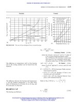
Reaction Injection Moldings
The
RIM
process predominantly uses TS polyurethane (PUR) plastics.
Others include nylon,
TS
polyester, and epoxy. PUR offers a large range
of product performance properties.
As
an
example PUR has a modulus
of elasticity in bending of
200
to
1400
MPa
(29,000
to
203,000
psi)
and heat resistance in the range of
90
to
200°C (122
to
392°F).
The
higher values
are
obtained when glass-fiber reinforces the PUR
(also
with nylon, etc.). The reinforced
RIM
process is called RRIM or
1
-
Overview
43
structural RIM (SRIM). Large and very thick RIM products can be
molded with or without reinforcements using fast cycles.
When compared
to
injection molding (IM) that processes
a
plastic
compound (polymer plus additives, etc.), RIM uses
two
liquid
PUR
chemical monomer components (poly01 and isocyanate) that are mixed
to
produce the polymer (plastic). Additives such as catalysts,
surfactants, fillers, reinforcements, and/or blowing agents are also
incorporated. Their purpose
is
to
propagate the reaction and form
a
finished product possessing the desired properties
Mixing is by a rapid impingement in
a
chamber (under high pressure in
a specially designed mixing head)
at
relatively low temperatures before
being injected into a closed mold cavity at low pressure.
An
exothermic
chemical reaction occurs during mixing and
in
the cavity requiring
less
energy than the conventional
IM
system. Polymerization of the
monomer mixture in the mold allows for the custom formulation of
material properties and kinetics
to
suit a particular product application.
RIM
is the logical process
to
consider at least for molding large and/or
thick products. With RIM technology, cycle times of
2
min and less
have been achieved
in
production for molding large
and
thick
[
10
cm
(3.9
in.)] products.
It
is less competitive for small products. Capital
requirements for RIM processing equipment are rather low when
compared with injection molding equipment (includes mold) that
would be necessary
to
mold products of similar large size.
Rotational Moldings
This method, like blow molding, is used
to
make hollow one-piece
TP
parts.
RM
consists of charging a measured amount of
TP
into
a
warm
mold cavity that is rotated in an oven about
two
axes. In the oven, the
heat penetrates the mold, causing the plastic, if it is in powder form, to
become tacky and adhere
to
the mold female cavity surface, or if it is in
liquid form,
to
start
to
gel on the mold cavity surface. Since the molds
continue
to
rotate during the heating cycle, the plastic
will
gradually
become distributed on the mold cavity walls through gravitational
force.
As
the cycle continues, the plastic melts completely, forming
a
homogeneous layer of molten plastic. After cooling, the molds are
opened and
the
parts removed.
RM
can produce quite uniform wall thicknesses even when
the
product
has a deep draw of the parting line or small radii. The liquid or
powdered plastic used in this process flows freely into corners or other
deep draws upon the mold being rotated and is fused/melted by heat
passing through the mold’s wall.
44
Plastics Engineered Product Design
This
process is particularly cost-effective for small production runs and
large product sizes. The molds
are
not subjected
to
pressure during
molding,
so
they can be made relatively inexpensively out of thin sheet
metal. The molds may also be made from lightweight cast aluminum
and electroformed nickel, both of them light in weight and low in cost.
Large rotational machines can be built economically because they use
inexpensive gas-fired
or
hot air ovens with the lightweight mold-
rotating equipment.
Variables
Even though equipment operations and plastic compounded materials
have understandable and controllable variables that influence
processing, the usual most uncontrollable variable in
the
process can be
the plastic material. The degree
of
properly compounding or blending
by the plastic manufacturer, converter, or in-house by
the
fabricator
is
important. With the passing of time and looking ahead, existing
material and equipment variabilities are continually reduced due to
improvement in their manufacturing and process control capabilities.
However they still exist.
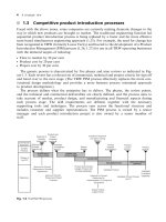
FALLO Approach
-
__.I
Conditions that
are
important in making plastic products the success it
has worldwide are summarized in
Fig.
1.15.
All designs, processes, and
materials
fit
into this overall
FALLO
(Follow
ALL
Opportunities)
approach flow chart
that
produces products meeting required
performance and cost requirements.
Designers and processors, needing to produce qualified products at the
lowest cost have
used
the
basic concept
of
the
FALLO
approach. This
approach makes one aware that many steps are involved
to
be
successfd, all of which must be coordinated and interrelated.
It
starts
with the design that involves specifjwg the plastic and specifying the
manufacturing process. The specific process (injection, extrusion, blow
molding, thermoforming, and
so
forth) is an important part
of
the
overall scheme.