Plastics Engineered Product Design Part 4 potx
Bạn đang xem bản rút gọn của tài liệu. Xem và tải ngay bản đầy đủ của tài liệu tại đây (1007.88 KB, 40 trang )
100
Plastics
Engineered Product Design
~
-* > *___I-
*
-
r'??a:~i.
2-2
Axial compression with three shear
modes
F
Axial
about
the
axial axis and torsion perpendicular
to
that
axis.
This
configuration
is
a
combination of Figs.
2.20
and
2.21.
For auxiliary generators and compressors any of these configurations
would
be
viable. However, each individual application has its own
design requirements.
One of
the
parameters to consider when applying an elastic suspension
system
to
an energy-producing device is
the
degree of motion that will
be acceptable
to
the
installation.
The performance of elastomers is of major interest and concern
to
the
design engineer. The readily available data concern
the
tensile-
elongation factor, the compression set, results from durometer tests,
and information on oil resistance, heat aging, and the static modulus.
In designing for
a
given environment, certain information makes the
designer's job easier and the actual results closer to that predicted.
These
types
of
data are normally generated
at
the designer's facility with
in-house-developed test equipment and procedures. They include:
(
1)
dynamic modulus at various strains, frequencies, and temperatures;
(2)
ozone resistance at different concentration
levels;
(3)
loss
factor
at
various strains, frequencies, and temperatures;
(4)
fatigue of various
shape factors and cyclic strains and temperatures;
(5)
effects of different
ingredients such as carbon black;
(6)
drift and set characteristics
at
various initial strains and temperatures; and
(7)
electrical resistance.
2
-
Design Optimization
101
~ ~~
Rapid
~
__x
~-
loading
~
vxI*_
Different behavioral characteristics for a wide range of loading rates
have been reviewed. This review concerns load or strain duration that
are much shorter than those reviewed that are usually referred
to
as
being rapid impact loading. They range from a second or less (Fig.
2.22).
There are a number of basic forms of rapid impact loading or
impingement on products
to
which plastics react in a manner different
from other materials. These dynamic stresses include loading due
to
direct impact, impulse, puncture, frictional, hydrostatic, and erosion.
They have a difference in response and degree of response
to
other
forms of stress.
The concept of a ductile-to-brittle transition temperature in plastics is
well known in metals where notched metal parts cause brittle failure
when compared
to
unnotched specimens. There are differences such as
the short time moduli of many plastics compared with those in metals
that may be
200
MPa
(29
x
lo6
psi). Although
the
ductile metals often
undergo local necking during a tensile test, followed by failure in the
neck, many ductile plastics exhibit the phenomenon called a
propagating neck.
Rapid loading velocity
(Courtesy
of
Plastics
FALLO)
VELOCITY.
FT./SEC
1
-FWD
PROJECTILE
BATTED
BASEBALL
-?ITCHI0 BASEBALL
Io(1
-FOOTILL
HELMET
-TEN-FOOT FAU
-KO0
IMPACT TEST
REMIGERPITOR
OOOR-SUM
-HOUSEDOORSLAM
10
01
-CONVENTIONAL TENSILE STRENGTH
0
01
102
Plastics Engineered Product
Design
Impact
Impact loading analysis may take the form of design against impact
damage requiring an analysis under highate loading or design for
acceptable energy absorption, or
a
combination of the
two.
Impact
resistance
of
a structure
is
defined as its ability
to
absorb and dissipate
the energy delivered
to
it
during relatively high speed collisions with
other objects without sustaining damage that would damage its
intended performance.
To
determine whether failure will occur the acceptable energy absorption
case requires an analysis of the stress and strain distribution during
the
impact loading followed by comparison with materials impact failure data.
Whenever
a
product is loaded rapidly, it is subjected
to
impact loading.
Any product that
is
moving has kinetic energy. When
this
motion is
somehow stopped because of
a
collision, its energy must
be
dissipated.
The ability of a plastic product
to
absorb energy is determined by such
factors as its shape, size, thickness,
type
of material, method of processing,
and environmental conditions
of
temperature, moisture, and/or others.
Temperature conditions effect impact strength. The impact
strength
of
plastics is reduced drastically
at
low temperatures with the exception of
fibrous filled materials that improve in impact strength at low
temperature. The reduction in impact strength is especially severe if the
material undergoes
a
glass transition where the reduction
in
impact
strength is usually an order
of
magnitude.
From a design approach several design features affect impact resistance.
For example, rigidizing elements such as ribs may decrease a part’s impact
resistance, while less-rigid sections may absorb more impact energy
without damage by deflecting elastically. Dead sharp corners or notches
subjected
to
tensile loads during impact may decrease
the
impact rcsistance
of a product by acting as
stress
concentrators, whereas generous radii in
these
areas
may distribute
the
tensile
load
and
enhance the impact
resistance. This factor is particularly important for products comprised
of
materials whose intrinsic impact resistance is a strong hnction of
a
notch
radius.
An
impact resistance
that
decreases drastically
with
notch radius
characterizes such notch sensitive materials. Wd thickness
may
also
affect
impact resistance. Some materials have a critical thickness above which
the
intrinsic impact resistance decreases dramatically.
There
are
different methods used
to
determine
thc
impact resistance
of
plastics. They include pendulum methods (Izod, Charpy, tensile impact,
falling dart, Gardner, Dynatup, etc.) and instrumented techniques. In
the
case
of
the Izod test, what is measured
is
the energy required
to
break a test specimen transversely struck (the test can be done either
2
-
Design Optimization
103
with
the specimen notched or unnotched). The tensile impact test has a
bar loaded in tension and the striking force tends
to
elongate the bar.
Impact strengths
of
plastics are widely reported, these properties have
no particular design value. However, they are important, because they
can be used to provide an initial comparison of the relative responses of
materials. With limitations, the impact value of
a
material can broadly
separate those that can withstand shock loading from those that are
poorly in this response. The results provide guidelines that will be more
meaningfd and empirical
to
the designer.
To
eliminate broad general-
izations, the target is
to
conduct impact tests on the final product or, if
possible,
at
least on its components.
An impact test on products requires setting up
an
approach on how it
should be conducted. The real test is after the product has been in
service and field reports are returned for evaluation.
Regardless,
the
usual impact tests conducted on test samples can be useful if they are
properly related with product requirements.
Test and service data with
PVC
both rate low in notched Izod impact
tests and performs well in normal service applications that involve
impact loading. Another example is with some grades of rubber-
modified high impact
PSs
that show up well in the Izod test fail
on impact under field test conditions. These results have led
to
continual reexamination of the tests used
to
determine the toughness of
plastics.
There are thermoplastics that tend
to
be very notch sensitive on impact.
This is apparent from the molecular structure of the TP that consist of
random arrangements
of
plastic chains (Chapter
1).
If the material
exists in the glassy state at room temperature the notch effect is
to
cut
the chains locally and increase the stress on the adjacent molecular chains
which
will
scission and propagate the effect through the material. At
the
high loading rate encountered in impact loading
the
only form of
molecular response is the chain bending reaction which is limited in
extent and generally low in magnitude compared
to
the viscoelastic
response which responds at longer loading times.
TPs
impact properties can be improved if the material selected does not
have sufficient impact strength.
One
method is by altering the com-
position of the material
so
that it is no longer
a
glassy plastic
at
the
operating temperature of the product. In the case
of
PVC
this is done
by the addition
of
an impact modifier which can be
a
compatible plastic
such as an acrylic or a nitrile rubber. The addition of such
a
material
lowers the
T,
(glass transition temperature) and the material becomes
a
rubbery viscoelastic plastic with improved impact properties (Chapter
1).
104
Plastics
Engineered Product Design
-*.
-
-
*
-
__I_
Molecular orientation can improve impact
TP
properties.
As
an
example nylon has a fair impact strength but oriented nylon has a very
high transverse impact strength. The intrinsic impact strength of the
nylon comes from the polar structure of the material and the fact that
the polymer is crystalline. The substantial increase in impact strength as
a result of
the
orientation results from the molecular chains being
aligned. This makes them very difficult
to
break and, in addition, the
alignment improves
the
polar interaction between the chains
so
that
even when there is a chain break the adjacent chains hold the broken
chain and resist parting of
the
structure. The crystalline nature of the
nylon material also means that there
is
a larger stress capability at rapid
loading since the crystalline areas react much more elastically than the
amorphous glassy materials.
Other methods in which impact strength can be substantially improved
are by the use
of
fibrous reinforcing fillers and product design. With
reinforcements materials act as a stress transfer agent around the region
that is highly stressed by the impact load. Since most
of
the fibrous
fillers such as glass have high elastic moduli, they are capable of
responding elastically at the high loading rates encountered in impact
loading. Designwise prevent the formation of notched areas that act as
stress risers.
Especially under impact conditions the possibility of
localized stress intensification can lead
to
product failure. In almost
every case the notched strength is substantially less than the unnotched
strength.
Impulse
Impulse loading differs from impact loading. The load
of
two billiard
balls striking is an impact condition. The load applied
to
an automobile
brake shoe when the brake load is applied or the load applied
to
a
fishing line when a
strike
is made is an impulse load. The time constants
are short but not as short as the impact load and the entire structural
element
is
subjcctcd
to
thc
stress.
It
is difficult
to
generalize as
to
whether a plastic is stronger under
impulse loading than under impact loading. Since the entire load is
applied to the elastic elements in the structure the plastic will exhibit a
high elastic modulus and much lower strain
to
rupture. For example
acrylic and rigid
PVC
(polyvinyl chloride) that appear
to
be brittle
under normal loading conditions, exhibit high strength under impulse
loading conditions. Rubbery materials such as TP polyurethane
elastomers and other elastomers behave like brittle materials under
impulse loading. This is
an
apparently unexpected result that upon
analysis is obvious because the elastomeric rubbery response is a long
time constant response and the rigid connecting polymer segments that
are brittle are the ones that respond at high loading rates.
Impact loading implies striking the object and consequently there is
a
severe surface stress condition present before the stress is transferred
to
the bulk of the material. The impact load is applied instantly limiting
the straining rate only by the elastic constants of the material being
struck.
A
significant portion of the energy of impact is converted
to
heat at the point
of
impact and complicates any analytically exact
treatment of the mechanics of impact. With impulse loading the load is
applied at very high rates
of
speed limited by the member applying the
load. However, the loading is not generally localized and the heat
effects are similar to conventional dynamic loading in that the hysteresis
characteristics of the material determines the extent of heating and the
effects can be analyzed with reasonable accuracy.
Plastics generally behave in
a
much different manner under impulse
loading than they do under loading at normal straining rates. Some of
thc same conditions occur as under impact loading where the primary
response
to
load is
an
elastic one because there is not sufficient time for
thc viscoclastic elements
to
operate. The primary structural response in
thermoplastic is by chain bending and by stressing of the crystalline
areas of crystalline polymers. The response
to
loading is almost com-
pletely elastic for most materials, particularly when
the
time of loading
is of the order of milliseconds.
Improvements made with respect
to
impact loading for structures such
as fibers and orientations apply equally
to
impulse loading conditions.
Crystalline polymers generally perform well under impulse loading,
especially polar materials with high interchain coupling.
To
design products subjected to impulse loading requires obtaining
applicable data. High-speed testing machines are used
to
determine the
response of materials at millisecond loading rates. If this
type
data is not
available evaluation can be done from the results of the tensile impact
test. The test should be done with a series
of
loads below break load,
through the break load,
and
then estimating the energy of impact under
the non-break conditions as well as the tensile impact break energy.
Recognize that brittle plastics perform well and rubbery materials that
would seem
to
be a natural for impulse loading are brittle.
Puncture
Puncture loading is very applicable in applications with sheet and film
as well
as
thin-walled tubing or molding, surface skins of sandwich
106
Plastics Engineered Product Design
panels, and other membrane type loaded structures. The test involves a
localized force that is applied by a relatively sharp object perpendicular
to
the plane of the plastic being stressed. In the case of a thin sheet or
film the stresses cause the material
to
be
(1)
displaced completely away
from the plane of the sheet (compressive stress under the point of the
puncturing member) and
(2)
the restraint is by tensile stress in the sheet
and by hoop stress around the puncturing member (part of the hoop
stress is compressive adjacent to the point which changes
to
tensile
stress
to
contain the displacing forces). Most cases fall somewhere
between these extremes, but the most important conditions in practice
involve the second condition
to
a
larger degree than the first condition.
If the plastic is thick compared
to
the area
of
application of the stress, it
is effectively a localized compression stress with some shear effects as
the material is deformed below the surface of the
sheet.
Plastics that
are
biaxially oriented have good puncture resistance.
Highly polar polymers would be resistant
to
puncture failure because of
their tendency
to
increase in strength when stretched. The addition of
randomly dispersed fibrous filler
will
also add resistance to puncture
loads.
Anisotropic materials will have a more complicated force pattern.
Uniaxially oriented materials will split rather than puncture under
\puncturing loading.
To
improve the puncture resistance materials are
needed
with
high tensile strength. In addition, the material should have
a
high compression modulus to resist the point penetration into the
material. Resistance
to
notch loading is also important.
Friction
Friction is
the
opposing force that develops when
two
surfaces move
relative
to
each other. Basically there are
two
frictional properties
exhibited by any surface; static friction and kinetic friction. The ranges of
fiction properties are rather extensive. Frictional properties of plastics
are important in applications such
as
machine products and in sliding
applications such as belting and structural units such
as
sliding doors. In
friction applications suggested as well as in many others, there are
important areas that concern their design approach.
It
starts in plastic selection and modification
to
provide either high or
low friction as required by
thc
application. There
is
also determining
the
required geometry
to
supply the frictional force level needed by
controlling contact area and surface quality
to
provide friction level.
A
controlling factor limiting any particular friction force application is
heat dissipation. This is true if the application of the fiction loads
is
2
-
Design
Optimization
107
either a continuous process or a repetitive process with
a
high duty cycle.
The use of cooling structures either incorporated into the products or
by the use of external cooling devices such as coolants or airflow should
be
a
design consideration. For successful design the heat generated by
the friction must be dissipated as fast as it is generated
to
avoid
overheating and failure.
The relationship between the normal force and the friction force is used
to
define the coefficient of static friction. Coefficient of friction is the
ratio of the force that
is
required to start the friction motion of one
surface against another
to
the force acting perpendicular to the
two
surfaces in contact. Friction coefficients will vary for a particular plastic
fiom the value just as motion starts
to
the value it attains in motion.
The coefficient depends on the surface of the material, whether rough
or smooth. These variations and others make it necessary
to
do careful
testing for an application which relies on the friction characteristics of
plastics. Once the friction characteristics are defined, however, they are
stable for a particular material fabricated in a prescribed method.
The molecular level characteristics that create friction forces are the
intermolecular attraction forces of adhesion. If the two materials that
make up the sliding surfaces in contact have
a
high degree of attraction
for each other, the coefficient of friction is high. This effect is modified
by surface conditions and the mechanical properties of the materials. If
the material is rough there is a mechanical locking interaction
that
adds
to
the friction effect. Sliding under these conditions actually breaks off
material and the shear strength of the material is an important factor in
the fiction properties. If the surface
is
polished smooth the governing
factor induced by the surface conditions is the amount of area in
contact between the surfaces. In a condition of large area contact and
good adhesion, the coefficient of friction is high since there is intimate
surface contact.
It
is possible by the addition of surface materials that
have high adhesion to increase the coefficient of friction.
If one or both of the contacting surfaces have
a
low compression
modulus
it
is possible
to
make intimate contact between the surfaces
which will lead
to
high friction forces in the case of plastics having good
adhesion.
It
can add
to
the friction forces in another way. The dis-
placement of material in front
of
the moving object adds a mechanical
element
to
the friction forces.
In regard
to
surface contamination,
if
the surface
is
covered with
a
material that prevents the adhesive forces from acting, the coefficient is
reduced. If the material
is
a liquid, which has low shear viscosity, the
condition exists
of
lubricated sliding where the characteristics of the
liquid control the friction rather than the surface fiction characteristics
of the plastics.
The use of plastics for gears and bearings is the area in which friction
characteristics have been examined most carefdly.
As
an example highly
polar plastic such as nylons and the TP polyesters have, as
a
result of the
surface forces
on
the material, relatively low adhesion for themselves
and such sliding surfaces
as
steel. Laminated plastics make excellent
gears and bearings. The typical coefficient of friction for such materials
is
0.1
to
0.2.
When they are injection molded (IM) the
skin
formed
when the plastic cools against the mold tends
to
be harder and
smoother than
a
cut surface
so
that the molded product exhibit lower
sliding friction and are excellent for this type of application. Good
design for this type of application is
to
make the surfaces as smooth as
possible without making them glass smooth which tends
to
increase the
intimacy
of
contact and
to
increase the friction above
that
of a fine
surface.
To
reduce friction, lubricants are available that
will
lower the friction
and help
to
remove heat. Mixing of slightly incompatible additive
materials such as silicone oil into an IM plastic are used. Mer IM the
additive migrates
to
the surface of the product and acts as a renewable
source
of
lubricant for the product. In the case of bearings it is carried
still
hrther by making the bearing plastic porous and filling it with a
lubricating material in a manner similar
to
sintered metal bearings,
graphite, and molybdenum sulfide are
also
incorporated as solid lubricants.
Fillers can be used
to
increase the thermal conductivity of the material
such as glass and metal fibers. The filter can be
a
material like PTFE
(polytetrafluoroethylene)
plastic that has
a
much lower coefficient of
friction and the surface exposed material will reduce the fiiction.
With sliding doors or conveyor belts sliding on support surfaces
different type of low friction or low drag application is encountered.
The normal forces are generally small and the friction load problems are
of
the adhering type. Some plastics exhibit excellent surfaces for
this
type
of
application.
PTFEs
(tetrafluoroethylene) have the lowest coefficient
of any solid material and represent one of the most slippery surfaces
known. The major problem with PTFE
is
that its abrasion resistance is
low
so
that most of the applications utilize filled compositions with
ceramic filler materials
to
improve the abrasion resistance.
In addition
to
PTFE in reducing friction using solid materials as well as
films and coatings there are other materials with excellent properties for
surface sliding. Polyethylene and the polyolefins in general have low
surface friction, especially against metallic surfaces.
UHMWPE
(ultra
high molecular weight polyethylene) has an added advantage in that
it
has much better abrasion resistance and is preferred for conveyor
applications
and
applications involving materials sliding o\7er the
product. In the textile industry loom products also use this material
extensively because it can handle the effects of the thread and fiber
passing over
the
surface with low friction and relatively low wear.
There are applications where high frictions have applications such as in
torquc surfaccs in clutches
and
brakes. Some plastics such
as
poly-
urethanes
and
plasticized vinyl compositions have very high friction
coefficients. These materials make excellent traction surfaces for
products ranging from power belts
to
drive rollers where the plastics
either drives or is driven by another member. Conveyor belts made of
oriented nylon and woven fabrics are coated with polyurethane elastomer
compounds
to
supply both the driving traction and
to
move
the
objects
being conveyed up fairly steep inclines because
of
the high friction
generated. Drive rollers for moving paper
through
printing presses, copy
machines, and business machines are frequently covered with either
urethane or vinyl
to
act as the driver members with minimum slippage.
Erosion
Friction in basically the effect of erosion forces such as wind driven sand
or water, underwater flows of solids past plastic surfaces, and even the
effects of high velocity flows causing cavitation effects on material
surfaces. One major area for the utilization of plastics is on the outside
of moving objects that range from the front of automobiles
to
boats,
aircraft, missiles, and submarine craft. In each case
the
impact effects
of
the velocity driven particulate matter can cause surface damage
to
plastics. Stationary objects such as radomes and buildings exposed
to
the weather in regions with high and frequent winds are also exposed
to
this type of effect.
Hydrostatic
In applications where water is involved if the water does not wet the
surface, the tendency will be
to
have the droplets that
do
not impact
close
to
the perpendicular direction bounce off the surface with
considerably less energy transfer
to
the surface. Non-wetting coatings
reduce
the
effect of wind and rain erosion. Impact of air-carried solid
particulate matter is more closely analogous to straight impact loading
sincc the particles do not become disrupted by the impact. The main
characteristic required of the material, in addition
to
not becoming
brittle under high rate loading is resistance
to
notch fracture.
The ability
to
absorb energy by hysteresis effects is important, as is the
1
10
Plastics Engineered
Product
Design
case with the water. In many cases the best type of surface is an
elastomer with good damping properties and good surface abrasion
resistance.
An
example is polyurethane coatings and products that are
excellent for both water
and
particulate matter that is air-driven.
Besides such applications as vehicles, these materials are used in the
interior of sand
and
shot blast cabinets where they are constantly
exposed
to
this type of stress. These materials are fabricated into liners
in hoses for carrying pneumatically conveyed materials such as sand
blasting hoses and for conveyor hose for a wide variety of materials such
as sand, grain, and plastics pellets.
The method of minimizing the effects of erosion produced when the
surface impact loading by fluid-borne particulate matter, liquid or solid,
or cavitation loading is encountered, relates
to
material selection
and
modification. The plastics used should be ductile at impulse loading
rates
and
capable of absorbing the impulse energy and dissipating it as
heat by hysteresis effects. The surface characteristics of the materials in
terms of wettability by the fluid and frictional interaction with the solids
also
play a role. In this type of application the general data available for
materials should be supplemented by that obtained under simulated use
conditions since the properties needed
to
perform are not readily
predictable.
Cavitation
Another rapid loading condition in underwater applications is the
application of external hydrostatic stress
to
plastic structures (also steel,
etc.). Internal pressure applications such as
those
encountered in pipe
and tubing or in pressure vessels such as aerosol containers
are
easily
treated using tensile stress
and
creep properties of the plastic with the
appropriate relationships for hoop and membrane stresses. The
application of external pressure, especially high static pressure, has a
rather unique effect on plastics. The stress analysis for thick walled
spherical and tubular structures under external pressure is available.
The interesting aspect that plastics have in
this
situation
is
that the
relatively high compressive stresses increase the resistance of plastic
materials
to
failure. Glassy plastics under conditions of very high
hydrostatic stress behave
in
some ways like a compressible fluid.
The
density of the material increases and the compressive strength are
increased. In addition, the material undergoes sufficient internal flow
to
distribute the
stresses
uniformly throughout the product.
As
a
consequence, the plastic products produced fi-om such materials as
acrylic and polycarbonate make excellent view windows for undersea
vehicles that operate at extreme depths where the external pressures are
7MPa
(1000
psi)
and
more.
2
-
Design Optimization
I1
1
-
With increasing ship speeds, the development of high-speed hydraulic
equipment,
and
the variety of modem fluid-flow applications
to
which
metal materials are being subjected, the problem of cavitation erosion
becomes more important since
it
was first reported during
1873
(Chapter
8).
Erosion may occur in either internal-flow systems, such as
piping, pumps, and turbines, or in external ones like
ships’
propellers.
This
erosion action occurs in a rapidly moving fluid when there is a
decrease in pressure in the fluid below its vapor pressure and the
presence of such nucleating sources as minute foreign particles or
definite gas bubbles. Result is the formation of vapor bubble that
continues to grow until it reaches a region
of
pressure higher than its
own
vapor pressure
at
which time it collapses. When these bubbles
collapse near a boundary, the high-intensity shock waves (rapid loading)
that are produced radiate to the boundary, resulting in mechanical
damage
to
the material. The force of the shock wave or of the
impinging may still be sufficient
to
cause a plastic flow or fatigue failure
in
a
material after a number
of
cycles.
Materials, particularly steel, in cavitating fluids results in
an
erosion
mechanism that includes mechanical erosion and electrochemical
corrosion. Protection against cavitation is
to
use hardened materials,
chromium, chrome-nickel compounds, or elastomeric plastics.
Also
used are methods
to
reduce the vapor pressure
with
additives,
add
air
to
act as a cushion for the collapsing bubbles, reduce the turbulence, and/
or change the liquid’s temperature.
Rain
As
it has been reported since the
1940s
as
one walks through
a
gentle
spring rain one seldom considers that raindrops can be small destructive
“bullets” when they strike high-speed aircraft. These rapid loaded
bullet-like raindrops can erode paint coatings, plastic products, and
even steel, magnesium or. aluminum leading edges
to
such
an
extent
that
the surfaces may appear
to
have been sandblasted. Even the
structural integrity of the aircraft may
be
affected after several hours of
flight through rain.
Also
affected are commercial aircraft, missiles, high-
speed vehicles on the ground, spacecraft before and after
a
flight when
rain
is
encountered, and even buildings or structures that encounter
high-speed rainstorms. Critical situations can exist in flight vehicles,
since flight performance can be affected
to
the extent that
a
vehicle can
be destroyed.
First reports on rain erosion on aircraft were first reported during
WW
I1
when the
B-29
bomber was flying over
the
Pacific Ocean.
Aerodynamic
R.P
radar wing-type shaped structure on
the
B-29
was
1
12
Plastics Engineered Product Design
=
*1__1-
flying
at
a
so
called
(at
that time) high-speed was completely destroyed
by rain erosion (DVR was a flight engineer on
B-29).
The “Eagle
Wing” radome all-weather bomber airplanes were then capable of only
flying at
400
mph. The aluminum aerodynamic leading edges of wings
and particularly of the glass-fiber-reinforced
TI?
polyester-nose radomes
were particularly susceptible
to
this form of degradation. The problem
continues
to
exist, as can be seen on the front of commercial and
military airplanes with their neoprene protective coated
RP
radomes;
the paint coating over the rain erosion elastomeric plastic erodes and
then is repainted prior
to
the catastrophic damage
of
the rain erosion
elastomeric coating.
Extensive flight tests conducted
to
determine the severity of the rain
erosion were carried out in
1944.
They established that aluminum and
RP
leading edges
of
airfoil shapes exhibited serious erosion
after
exposure
to
rainfall of only moderate intensity. Inasmuch as this
problem originally arose with military aircraft, the
U.S.
Air
Force
initiated research studies at the Wright-Patterson Development
Center’s Materials Laboratory in Dayton, Ohio
(DVR
department
involved; young lady physicist actually developed
the
theory of rain
erosion that still applies).
It
resulted in applying an elastomeric
neoprene coating adhesively bonded
to
RP
radomes. The usual
5
mil
coating of elastomeric material used literally bounces off raindrops,
even from a supersonic airplane traveling through rain. Even though
a
slight loss (l%/mil of coating) of radar transmission occurred it was
better than losing
100%
when the radome was destroyed.
To determine the
type
of physical properties materials used
in
this
environment should have,
it
is necessary
to
examine the mechanics of
the impact of the particulate matter on the surfaces. The high kinetic
energy of the droplet is dissipated
by
shattering the drop,
by
indenting
the surface, and by frictional heating effects. The loading rate is high as
in impact and impulse loading, but
it
is neither as localized as the
impact load nor as generalized as the impulse load. Material that can
dissipate the locally high stresses through the bulk of the material will
respond well under this
type
of load. The plastic should not exhibit
brittle behavior at high loading rates.
In
addition, it should exhibit
a
fairly high hysteresis level that would
have the effect of dissipating the sharp mechanical impulse loads as
heat. The material will develop heat due to the stress under cyclical
load. Materials used are the elastomeric plastics used in
the
products or
as
a
coating on products.
2
-
Desiqn
Optimization
113
___1_1_
-
I
High
performance
-
-_
__llll_l _;_
~__-
mw-
’-
As
reviewed throughout this book the high performance materials are
engineering plastics such as polycarbonate, nylon, acetal, and reinforced
plastic
(RP).
Data
on
these
plastics are provided throughout this
book.
In this section information on
RPs
is presented since they can provide a
special form of high performance material that provides a designer with
different innovative latitudes of performances than usually reviewed in
textbooks.
Reinforced Plastic
They are strong, usually inert materials bound into a plastic
to
improve
its properties such as strength, stiffness/modulus
of
elasticity, impact
resistance, reduce dimensional shrinkage, etc. (Figs
2.2,
2.23,
&
2.24).
They include fiber and other forms of material. There are inorganic and
organic fibers that have the usual diameters ranging from about one
to
over
100
micrometers. Properties differ for
the
different types,
diameters, shapes, and lengths.
To
be effective, reinforcement must
form
a
strong adhesive bond with the plastic; for certain reinforcements
special cleaning, sizing, etc. treatments are used to improve bonds.
A
microscopic view of an
RP
reveals groups of fibers surrounded by the
matrix.
In general adding reinforcing fibers significantly increases mechanical
properties. Particulate fillers of various
types
usually increase the
modulus, plasticizers generally decrease the modulus but enhance
flexibility, and
so
on. These reinforced plastics
(RPs)
can also be called
composites. However
the
name composites literally identifies thousands
of
different combinations with very few that include the
use
of plastics.
In using the term composites when plastics are involved the more
appropriate term
is
plastic composite.
Figure
2-23
RPs
tensile
S-S
data
(Courtesy
of
Plastics
FALLO)
STEEL
4
w
E
0
0.05
0.10
STRAIN,
INCHES
/INCH
1
14
Plastics
Enqineered Product Desiqn
Figure
2.24
Properties
of
RPs and other materials
(Courtesy
of
Plastics
FALLO)
0
SPECIFIC
STRENGTH
MODULUS
SPECIFIC
m
CARBON/
GLASS1
WOOD
ALUMINUM
STEEL
EWXY EWXY
Types of reinforcements include fibers of glass, carbon, graphite, boron,
nylon, polyethylene, polypropylene, cotton, sisal, asbestos, metals,
whiskers, etc. Other
types
and forms of reinforcements include
bamboo, burlap, carbon black, platelet forms (includes mica, glass, and
aluminum), fabric, and hemp. There are whiskers
that
are metallic or
nonmetallic single crystals (micrometer size diameters) of ultrahigh
strength and modulus. Their extremely high performances (high
modulus of elasticity, high melting points, resistance
to
oxidation, low
weights, etc.) are attributed
to
their near perfect crystal structure,
chemically pure nature, and fine diameters that minimize defects. They
exhibit a much higher resistance
to
fracture (toughness) than other
types of reinforcing fibers (Chapter
1).
The advanced
RP
(ARP)
refers
to
a
plastic matrix reinforced
with
very
high strength, high modulus fibers that include carbon, graphite, aramid,
boron, and S-glass. They can
be
at
least
50
times stronger and
25
to
150
times stiffer than the matrix.
ARPs
can have
a
low density
(1
to
3
g/cm3), high strength
(3
to 7
GPa) and high modulus
(60
to
600
GPa).
It
can generally be claimed that fiber based
RPs
offer good potential for
achieving high structural efficiency coupled
with
a weight saving in
products, fuel efficiency in manufacturing, and cost effectiveness during
service life. Conversely, special problems can arise from
the
use of
RPs,
due
to
the extreme anisotropy
of
some
of
them,
the
fact that the
strength of certain constituent fibers
is
intrinsically variable, and
2
-
Design
Optimization
1
15
because the test methods for measuring
RPs'
performance need special
consideration if they are
to
provide meaningfd values.
Orientation
of
Reinforcement
RPs
behavior is dominated by
the
arrangement and the interaction of
the stiff, strong reinforcing fibers with the less stiff, weaker plastic
matrix. The fiber arrangement determines
the
behavior of
RPs
where
a
major advantage is that directional properties can be maximized.
Arrangements include the use of woven (with different weaves) and
nonwoven (with different lengths and forms) fabrics.
Design
theories
of combining actions of plastics and reinforcement
arrangements have been developed and used successfully. Theories are
available
to
predict overall behavior based on the properties of fiber and
matrix. In a practical design approach, the behavior can use the original
approach analogous
to
that used in wood for centuries where individual
fiber properties are neglected; only the gross properties, measured at
various directions relative
to
the grain,
are
considered.
This
was the
initial design evaluation approach used during the
1940s.
Orientation Terms
Orientation terms of
RP
directional properties include
the
following:
Anisotropic construction
RP
properties are different in different
Balanced construction
RP
in which properties are symmetrical along
Bidirectional construction
RP
with the fibers oriented in various
directions along the laminate flat plane.
the laminate flat plane.
directions in the plane of
the
laminate usually identifjmg a cross
laminate with the direction
90"
apart.
to
point in a heterogeneous mass.
Heterofleneous construction
RP
material's composition varies from point
Homojeneous construction Uniform
RP.
Isotropic construction
RPs
having uniform properties in all directions
Nonisotropic construction
RJ?
does
not
have uniform properties in all
Orthotropic constraction
RP
having mutually perpendicular planes of
along the laminate flat plane.
directions.
elastic symmetry along
the
laminate flat plane.
1
16
Plastics Engineered Product Design
Unidirectional, construction
Refers to fibers that are oriented in the
same direction (parallel alignment) such as filament-winding,
pultrusion, unidirectional fabric laminate, and tape.
RPs
can be constructed from
a
single layer or built up from multiple
layers using fiber preforms, nonwoven fabrics, and woven fabrics. In
many products woven fabrics are very practical since they drape better
over 3-D molds than constructions that contain predominantly straight
fibers. However they include kinks where fibers cross.
Kinks
produce
repetitive variations and induce local stresses in the direction of
reinforcement with some sacrifice in properties. Regardless, extensive
use of fabrics
is
made based on their advantages.
The glass content of
a
part has
a
direct influence on its mechanical
properties where the more glass results in more strength.
This
relates
to
the ability
to
pack the reinforcement. Fiber content can be measured in
percent by weight of the fiber portion
(wt%)
or percent by volume
(~01%).
(Fig.
2.25)
When content is only in percent, it usually refers
to
wt%.
Depending on how glass fibers are arranged content can range
from
65
to
95.6
wt%
or up
to
90.8
~01%.
When one-half of the strands
are
placed at right angles
to
each half, glass loadings range from
55
to
88.8
wt%
or up
to
78.5
vol% (Fig.
2.26).
Basic
Design
Theory
In designing
RPs,
certain important assumptions are made
so
that
two
materials act together and the stretching, compression, twisting of
fibers and
of
plastics under load is the same; that is, the strains in fiber
and plastic are equal. Another assumption is that the
RP
is elastic, that
is,
strains are directly proportional
to
the stress applied, and when
a
load
is
removed the deformation disappears. In engineering terms, the
material obeys Hooke’s Law. This assumption is a close approximation
to the actual behavior in direct stress below the proportional limit,
particularly in tension, where the fibers carry essentially all the
stress.
The assumption is possibly less valid in shear where the plastic carries a
substantial portion of the stress.
In this analysis it
is
assumed that all the glass fibers are straight;
however, it is unlikely that
this
is true, particularly with fabrics. In
practice,
the
load is increased with fibers not necessarily failing
at
the
same time. Values of a number of elastic constants must be known in
addition
to
strength properties of the resins, fibers, and combinations.
In
this
analysis, arbitrary values are used that are low for elastic
constants and strength values. Any values can be used; here the theory
is illustrated.
'')
<'
-
I
Weight to volume relation example
'iqu:e
2
25
Fiber arrangement
for
filament wound fabricated products
influences properties
Per
cent
glass
by
weight
or
volume
Any material, when stressed, stretches or
is
otherwise deformed. If the
plastic and fiber are firmly bonded together, the deformation is the
same. Since the fiber is more unyielding, a higher stress is developed in
the glass than the plastic. If the stress-strain relationships
of
fiber and
plastic are known, the stresses developed in each for a given strain can
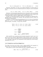
be computed and their combined action determined. Fig. 2.27 stress-
strain
(S-S)
diagrams provide the basis for this analysis;
it
provides
related data such as strengths and modulus.
These
S-S
diagrams may be applied
to
investigate a rod in which half
of
the volume is glass and the other half is plastic. If the fibers are parallel
to
the axis of the rod, at any cross-section, half
of
the total is fiber with
half plastic.
If
the rod is stretched
OS%,
the
S-S
diagrams show that the
glass
is
stressed
to
50,000
psi (345 MPa), resin
B
at 7,500 psi
(52
MPa),
and resin
C
at
2,500
psi
(17
MPa). If the rod has a total cross-
section of
Y2
in2, the glass is
Y4
in2. The total load
on
the glass is
Y4
x
50,000
or 12,500 lb. Similarly resin
B
is
1,875
Ib and resin
C
is
625
lb.
The load required
to
stretch the rod made of resin
B
becomes the sum
of
glass and resin load or 14,375 lb. With resin
C
the load
is
13,125 Ib.
The foregoing can be put into the form of an equation:
OA
=
0p4f
+
0p-4,
(2-1
5)
1
18
Plastics
Engineered Product Design
Figure
2-27
Analysis
of
RPs
stress-strain curves (Courtesy
of
Plastics
FALLO)
?o
strain
%
strain
a
=
mean stress in tensity
on
entire cross-section
of
=
stress intensity
in
fiber
a,
=
stress intensity in resin
A
=
total
cross-sectional area
Af
=
cross-sectional area
of
fiber
A,
=
cross-sectional area of resin
If the moduli of elasticity, as measured by the tangents
to
the
S-S
diagrams, are known the following equations are obtained
E,
=
modulus of elasticity of resin
Ef
=
modulus
of
elasticity of fiber
Substituting (2-16) in (2-15) results
in:
aA
=
of
(Af
+
$Ar)
(2-16)
(2-17)
Referring
to
Fig. 2.27, the tangent
to
the
S-S
curve
for
glass gives a
value
of
Ef
=
10
x
lo6
psi.
The resin tangents are given for
B
and
C
at
1.5
x
lo6
psi and
0.5
x
lo6
psi, respectively. Substituting these values in
2
-
Design Optimization
119
y____p-p^
-_I-x-
-
.
Eq.
(2-17)
results in:
Resin
B
oA
=
50,000
=
14,375
Ib
or
(T
=
28,750
psi
Resin
C
aA
=
50,000
=
13,125
Ib
o
=
26.250
psi
(2- 18)
(2-19)
Average values of modulus
of
elasticity of the entire cross-section may
be computed by dividing
0
by the strain. The strain is
0.5%,
therefore
the
two
average values of
E
of the rod, incorporating resins
B
and
C,
are
5.75
x
lo6
psi and
5.35
x
lo6-
psi, respectively.
For
a
cross-section made up
of
a
number of different materials, Eq.
(2-
15)
may be generalized
to:
i=n
OA
=
C
o;A;
(2-20)
i=
1
in which
0
is the tensile strength and
A,
the cross-sectional area of any
component of the cross-section. This equation can be still further
generalized
to
include tension, compression, and shear:
i=n
SA
=
C
SjAi
(2-21)
i=
1
in which
Si
is the strength property of the cross-sectional area Ai, and
S
is the mean strength property over the entire cross-section
A.
Similar
to
finding the overall modulus of
a
cross-section, the equation
becomes:
/=n
EA
=
2
EiA;
(2-22)
i=l
in which
E
is the overall modulus of elasticity,
A
the total cross-section,
and
Ei
the modulus of elasticity corresponding
to
the partial cross-
sectional area
4.
For shear modulus
G
the equation becomes:
i=n
GA
=
C
GjA;
(2-23)
i=l
120
Plastics
Engineered
Product
Design
Fiber Strength Theory
The deformation and strength of filamentary structures subjected
to
combined loading can be theoretically predicted using experimentally-
determined intrinsic stiffnesses and strength of the individual constituent
layers. In order
to
have
an
integrated material and structure design, the
gross
properties as hnctions of the micromechanical parameters represent
an important issue on the continuing and expanding
use
of
RPs.
It
has
been established, both
in
theory and experiment, that four principal
elastic moduli and three principal strengths govern the deformation and
strength of unidirectional fiber
RPs.
With the aid of
a
yield condition, the
initial
failure
of filamentary structures can be predicted. After
the
initial
failure, the structure may carry additional loads.
An
analysis of
a
partially
failed or degraded structure can be used
to
predict the ultimate
deformation and strength.
With an understanding of the
gross
behavior of a filamentary structure,
a proper assessment
of
the mechanical and geometric properties of the
constituent materials is possible. In particular, the use of fiber strength,
the binding resin matrix, and the interface may be placed in
a
perspective based on
the
results of a mathematical analysis. They
provide accurate guidelines for the design of
RPs.
A
better understanding exists of the elastic stifhess of filamentary
materials than of the strengths. The generalized Hooke’s law
is
usually
accepted as the governing equation of the linear elastic deformation of
RP
materials. The simultaneous or sequential modes
of
deformation and
fracture are difficult
to
describe from the phenomenological standpoint.
In general, a strength theory on one criterion
will
not be sufficient
to
cover
the
entire range of failure modes of
RP.
In addition, fabrication
variables and test methods are also known
to
introduce uncertainties in
strength data
that
makes the verification of theories more difficult.
A
macroscopic theory of strength is based
on
a
phenomenological
approach.
No
dircct rcference
to
the mode of deformation and fracture
is made. Essentially, this approach employs the mathematical theories of
elasticity and tries
to
establish
a
yield or failure criterion. Among the
most popular strength theories are those based
on
maximum stress,
maximum strain,
and
maximum work. The maximum stress theory
states that, relative
to
the material symmetry axes
x-y,
failure of the
RP
will occur if one
of
three ultimate strengths is reached. There are three
inequalities, as follows:
(2-24)
(2-25)
(2-26)
With negative normal stress components, compressive strengths
designated by
X'
and
r'
must
be
used:
0,lX
(2-27)
0,s
Y
(2-28)
Shear strength
S
has no directional property
and
it retains the same
value for both positive and negative shear stress components.
The
maximum strain theory is similar
to
the maximum stress theory.
Associated with each strain component, relative
to
the
material
symmetry axes,
e, e,,,
or
e,
there is an ultimate strain or
an
arbitrary
proportional limit,
X,
T,
or
S,,
respectively. The maximum strain
theory can be expressed in terms of the following inequalities:
e,
I
X,
(2-29)
e,l
Ye
(2-30)
ex<
S,
(2-31)
Where
e,
and
yy
are negative, use the following inequalities:
e,lX>
(2-32)
e,<
Y,
(2-33)
The maximum work theory in plane stress takes the following form:
(:)2
-
(>)("x.)
+
(?)*
+
($2
=
1
(2-34)
If
0,
and
or
are negative, compressive strengths
X'
and
T'
should
be
used in
Eq.
2-34,
respectively.
In the following reviews, the tensile and compressive strengths of
unidirectional and laminated
RPs,
based on the three theories, is
computed and compared with available data obtained from glass fiber-
epoxy
RPs.
The uniaxial strength of unidirectional
RPs
with
fiber
orientation
e
can
be
determined according
to
the maximum theory.
Strength is determined by the magnitude
of
each stress component
according
to
Eqs.
2-24,2-25, and 2-26 or
Eqs.
2-27 and 2-28.
As
fiber
orientation varies fiom
0"
to
90", it is only necessary
to
calculate the
variation of the stress components as a function of
e.
This
is
done by
using
the
usual transformation equations of
a
second rank tensor, thus:
(J,
=
G~
COS^
e
0,
=
(J,
sinZ
8
ox=
(J,
sin
8
cos
8
(2-35)
(2-36)
(2-37)
where
om
0,
0,
are the stress components relative
to
the material
122
Plastics
Engineered Product Design
symmetry
axes,
i.e.,
0,
is the normal stress along the fibers,
tsp
transverse
to
the fibers,
0,
the shear stress;
(J~
=
uniaxial stress along
to
the test
specimen. Angle
8
is measured between the
l-axis
and the fiber
axis.
By
combining
Eqs.
2-35, 2-36,
and
2-37
with
2-24, 2-25,
and
2-26,
the
uniaxial strength
is
determined by:
(2-38)
(2-39)
(2-40)
The maximum strain theory can be determined by assuming
that
the
material is linearly elastic up
to
the ultimate failure.
The
ultimate strains
in
Eqs.
2-29, 2-30,
and
2-31
as
well as
2-32
and
2-33
can be related
directly
to
the strengths as follows:
Xe
=
WE11
(2-41)
Ye
=
WE22
S,
=
S/G
The
usual stress-strain relations
of
orthotropic materials
is:
1
e,
=
-
(0,
-
v124
Ell
I
ev
=
-
(ov
-
v120,)
E22
1
e,
=
-
6,
G
(2-42)
(2-43)
(2-44)
(2-45)
(2-46)
Substituting
Eq.
2-35, 2-36,
and
2-37
into
2-44, 2-45,
and
2-46
results in,
e,
=
-
(cos2
6-
v12 sin2
e)o1
Ell
1
-
(sin2
6-
v21 cos2
@al
eV
=
E22
1
e,
=
-
(sin
@cos
6)ol
G
(2-47)
(2-48)
(2-49)
Finally, substituting
Eqs.
2-47, 2-48,
and
2-49
and
2-41, 2-42,
and
2-43
into
Eqs.
2-29,2-30,
and
2-31,
and after rearranging, one obtains
the uniaxial strength based on the maximum theory:
o1
I
X/(cos2
e
-
v12sin2
e)
(2-50)
2
-
Design Optimization
123
I
Y/(sin2
e
-
v21cos2
e)
I
X/(sin
8
-
cos
0)
(2-51)
(2-52)
The maximum work theory can be obtained directly by substituting
Eq.
2-35,2-36,
and
2-37
into
Eq.
2-34:
(2-53)
Determining the strength of laminated
RPs
is
no more difficult
conceptually than determining the strength of unidirectional
RPs.
It
is
only necessary
to
determine the stress and strain components that exist
in each constituent layer. Strength theories can then be applied
to
ascertain which layer of the laminated composite has failed. Stress and
strain data is obtained for E-glass-epoxy, and cross-ply and angle-ply
RPs.
Under uniaxial loading, only
N,
is the nonzero
stress
resultant and
when temperature effect is neglected, the calculations become:
ei
=(A;,
+
zB'JNl
(2-54)
Ocf)
=
&j
[A'jl
+
zB)~]N~
(2-55)
where
A'
and
B'
matrices
are
the in-plane and coupling matrices of
a
laminated anisotropic composite.
The stress and strain components can be computed from
Eqs.
2-54
and
2-55.
They can then be substituted into the strength theories, from
which the maximum
Ni,
the uniaxial stress resultant can be determined.
Uniaxial tensile strengths of unidirectional and laminated composites
made of
E-glass-epoxy
systems are obtained.
Also,
uniaxial axial-com-
pressive strengths are obtained. The three strength theories can be
applied
to
the glass-epoxy
RP
by using the following material coefficients:
E,,
=
7.8
x
IO6
psi
EZ2
=
2.6
x
IO6
psi
G
vi2
=
0.25
=
1.25
x
IO6
psi
(2-56)
X
=
150
ksi
X'
=
150
ksi
Y
=
4
ksi
Y
=
20
ksi
5
=
8
ksi
The maximum stress theory
is
shown as solid lines in
Fig.
2.28.
On
the
right-hand side of
the
figure
is
the uniaxial strength of directional
RPs
with fiber orientation
8
from
0"
to
90";
on the left-hand side, laminated
RPs
with helical angle
a
from
0"
to
90".
Both tensile and compressive
loadings are shown. The tensile data are
the
solid circles and the com-
124
Plastics Engineered Product Design
Figure
2.28
Maximum
stress
theory
a
n
pressive are squares. Tensile data are obtained from dog-bone specimens.
Compressive data are from specimens with uniform rectangular cross-
sections.
Figure
2.29 shows the comparison between the maximum strain theory
and the same experimental data shown in Fig.
2.28. The formats are
similar.
Fig.
2.28 shows a comparison between the maximum work
theory
of
the same experimental data as shown in Figs 2.29 and 2.30.
Based on a Tsai review,
it
shows that the maximum work theory is more
accurate than the maximum stress and strain theories. The maximum
work theory encompasses the following additional features.
1.
2.
3.
4.
There is a continuous variation, rather than segmented variation, of
the strength as
a
finction
of
either the fiber orientation 8 or helical
angle
a.
There is a continuous decrease as the angles
8
and
a
deviate from
0".
There is no rise in axial strength, as indicated by
the
maximum
stress
and
strain theories.
The uniaxial strength is plotted on a logarithmic scale and
an
error
of
a factor of 2 exists in the strength prediction of the maximum
stress and strain theories in the range of
30".
A fundamental difference between the maximum work and the
other theories lies in the question of interaction among the failure
modes.
The
maximum stress and strain theories assume that there is
no interaction among the three failure modes (axial, transverse, and
shear failures).