Intro to Naval Architecture 3 2010 Part 3 docx
Bạn đang xem bản rút gọn của tài liệu. Xem và tải ngay bản đầy đủ của tài liệu tại đây (1.3 MB, 30 trang )
50
FLOTATION
AND
STABILITY
Similarly
the
vertical
moment
of
volume
shift
is:
From
the figure it
will
be
seen that:
This
is
called
the
wall-sided
formula.
It is
often
reasonably accurate
for
full
forms
up to
angles
as
large
as
10°.
It
will
not
apply
if the
deck edge
is
immersed
or the
bilge emerges.
It can be
regarded
as a
refinement
of
the
simple expression
GZ
=
GM sin
<p.
Influence
on
stability
of
a freely
hanging
weight
Consider
a
weight
w
suspended
freely
from a
point
h
above
its
centroid.
When
the
ship
heels
slowly
the
weight moves transversely
and
takes
up
a new
position, again
vertically
below
the
suspension point.
As far as the
ship
is
concerned
the
weight
seems
to be
located
at the
suspension
point. Compared
to the
situation
with
the
weight
fixed, the
ship's
centre
of
gravity
will
be
effectively
reduced
by
GGi
where:
This
can be
regarded
as a
loss
of
metacentric
height
of
GGj.
Weights
free
to
move
in
this
way
should
be
avoided
but
this
is not
always
possible.
For
instance, when
a
weight
is
being
lifted
by a
shipboard crane,
as
soon
as the
weight
is
lifted
clear
of the
deck
or
quayside
its
effect
on
stability
is as
though
it
were
at the
crane head.
The
result
is a
rise
in G
which,
if the
weight
is
sufficiently
large,
could
cause
a
stability
problem. This
is
important
to the
design
of
heavy
lift
ships.
FLOTATION
AND
STABILITY
51
Figure
4,16
Fluid
free
surface
Effect
ofUquidfree
surfaces
A
ship
in
service
will
usually have tanks which
are
partially
filled
with
liquids.
These
may be the
fuel
and
water tanks
the
ship
is
using
or may
be
tanks carrying
liquid
cargoes.
When such
a
ship
is
inclined
slowly
through
a
small
angle
to the
vertical
the
liquid surface
will
move
so as
to
remain
horizontal.
In
this
discussion
a
quasi-static
condition
is
considered
so
that slopping
of the
liquid
is
avoided.
Different
considerations
would apply
to the
dynamic conditions
of a
ship rolling.
For
small
angles,
and
assuming
the
liquid surface
does
not
intersect
the
top or
bottom
of the
tank,
the
volume
of the
wedge that moves
is:
11);
2
<p
dx,
integrated over
the
length,
I,
of the
tank.
Assuming
the
wedges
can be
treated
as
triangles,
the
moment
of
transfer
of
volume
is:
where
I\
is the
second moment
of
area
of the
liquid,
or
free, surface.
The
moment
of
mass moved
=p
f
f»/
1
,
where
p
f
is the
density
of the
liquid
in
the
tank.
The
centre
of
gravity
of the
ship
will
move because
of
this
shift
of
mass
to a
position
Gj
and:
where
p is the
density
of the
water
in
which
the
ship
is floating and V
is
the
volume
of
displacement.
52
FLOTATION
AND
STABILITY
The
effect
on the
transverse movement
of the
centre
of
gravity
Is
to
reduce
GZby
the
amount
GGi
as in
Figure
4.16(b).
That
is,
there
is an
effective
reduction
in
stability. Since
GZ=
GMsin
(p
for
small angles,
the
influence
of the
shift
of G to
Gj
is
equivalent
to
raising
G to
G
2
on the
centre line
so
that
GGj
=
GGg
tan
<p
and the
righting moment
is
given
by:
Thus
the
effect
of the
movement
of the
liquid
due to its
free
surface,
is
equivalent
to a
rise
of
GG^
of the
centre
of
gravity,
the
'loss'
of GM
being:
Free
surface
effect
GGg
=
p
f
/i/pV
Another
way of
looking
at
this
is to
draw
an
analogy with
the
loss
of
stability
due to the
suspended weight.
The
water
in the
tank with
a
free
surface
behaves
in
such
a way
that
its
weight force acts through some
point above
the
centre
of the
tank
and
height
I\/v
above
the
centroid
of
the fluid in the
tank, where
v is the
volume
of fluid. In
effect
the
tank
has its own
'rnetacentre'
through which
its fluid
weight acts.
The fluid
weight
is
p
f
v
and the
centre
of
gravity
of the
ship
will
be
effectively
raised through
GG^
where:
This loss
is the
same whatever
the
height
of the
tank
in the
ship
or its
transverse position.
If the
loss
is
sufficiently
large,
the
metacentric
height becomes negative
and the
ship heels over
and may
even capsize.
It
is
important that
the
free
surfaces
of
tanks should
be
kept
to a
minimum.
One way of
reducing them
is to
subdivide wide tanks into
two
or
more narrow
ones.
In
Figure 4.17
a
double bottom tank
is
shown
with
a
central division
fitted.
figure
4.17
Tank
subdivision
FLOTATION
AND
STABILITY
53
If
the
breadth
of the
tank
is
originally
B,
the
width
of
each
of the two
tanks,
created
by the
central division,
is
J5/2.
Assuming
the
tanks have
a
constant section,
and
have
a
length,
4 the
second moment
of
area
without
division
is
IB
3
/12.
With
centre
division
the sum of the
second
moments
of
area
of the two
tanks
is
(//12)
(B/2)
3
X 2 =
1&/48
That
is, the
introduction
of a
centre division
has
reduced
the
free
surface
effect
to a
quarter
of its
original value. Using
two
bulkheads
to
divide
the
tank into three equal width sections reduces
the
free
surface
to a
ninth
of its
original value. Thus subdivision
is
seen
to be
very
effective
and it is
common practice
to
subdivide
the
double bottom
of
ships.
The
main tanks
of
ships carrying liquid cargoes must
be
designed
taking
free
surface
effects
into account
and
their breadths
are
reduced
by
providing centreline
or
wing bulkheads.
Free
surface
effects
should
be
avoided where possible
and
where
unavoidable
must
be
taken into account
in the
design.
The
operators
must
be
aware
of
their significance
and
arrange
to use the
tanks
in
ways
intended
by the
designer.
The
inclining
experiment
As
the
position
of the
centre
of
gravity
is so
important
for
initial
stability
it
is
necessary
to
establish
it
accurately.
It is
determined
initially
by
calculation
by
considering
all
weights making
up the
ship
-
steel,
outfit,
fittings,
machinery
and
systems
- and
assessing
their
individual
centres
of
gravity.
From these data
can be
calculated
the
displacement
and
centre
of
gravity
of the
light ship.
For
particular conditions
of
loading
the
weights
of all
items
to be
carried must then
be
added
at
their
appropriate centres
of
gravity
to
give
the new
displacement
and
centre
of
gravity.
It is
difficult
to
account
for all
items accurately
in
such
calculations
and it is for
this reason that
the
lightship weight
and
centre
of
gravity
are
measured experimentally.
The
experiment
is
called
the
inclining
experiment
and
involves causing
the
ship
to
heel
to
small angles
by
moving known weights known
distances
tranversely
across
the
deck
and
observing
the
angles
of
inclination.
The
draughts
at
which
the
ship
floats are
noted
together
with
the
water density. Ideally
the
experiment
is
conducted when
the
ship
is
complete
but
this
is not
generally
possible.
There
will
usually
be
a
number
of
items both
to go on and to
come
off the
ship (e.g. staging,
tools
etc.).
The
weights
and
centres
of
gravity
of
these must
be
assessed
and the
condition
of the
ship
as
inclined corrected.
A
typical
set up is
shown
in
Figure 4.18.
Two
sets
of
weights, each
of
w,
are
placed
on
each side
of the
ship
at
about amidships,
the
port
and
starboard sets being
h
apart.
Set 1 is
moved
a
distance
h
to a
position
54
FLOTATION
AND
STABILITY
Figure
4.18
Inclining experiment
alongside
sets
3 and 4. G
moves
to
GI
as the
ship inclines
to a
small
angle
and B
moves
to
Bj
.
It
follows
that:
<p
can be
obtained
in a
number
of
ways.
The
commonest
is to use two
long pendulums,
one
forward
and one
aft,
suspended
from
the
deck
into
the
holds.
If d and
/
are the
shift
and
length
of a
pendulum
respectively,
tan
<p
=
d/L
To
improve
the
accuracy
of the
experiment, several
shifts
of
weight
are
used.
Thus,
after
set 1 has
been moved,
a
typical
sequence would
be
to
move successively
set 2,
replace
set 2 in
original
position
followed
by
set
1
.
The
sequence
is
repeated
for
sets
3 and 4. At
each stage
the
angle
of
heel
is
noted
and the
results
plotted
to
give
a
mean angle
for
unit
applied moment. When
the
metacentric
height
has
been obtained,
the
height
of the
centre
of
gravity
is
determined
by
subtracting
GM
from
the
value
of
,KM
given
by the
hydrostatics
for the
mean draught
at
which
the
ship
was floating.
This
KG
must
be
corrected
for the
weights
to go
on and
come off.
The
longitudinal
position
of B, and
hence
G, can be
found
using
the
recorded
draughts.
To
obtain accurate results
a
number
of
precautions have
to be
observed. First
the
experiment should
be
conducted
in
calm water
with
little
wind. Inside
a
dock
is
good
as
this eliminates
the
effects
of
tides
and
currents.
The
ship must
be floating
freely
when
records
are
taken
so
any
mooring lines must
be
slack
and the
brow must
be
lifted
clear.
All
weights
must
be
secure
and
tanks must
be
empty
or
pressed
full
to
avoid
FLOTATION
AND
STABILITY
55
free
surface
effects.
If the
ship
does
not
return
to its
original
position
when
the
inclining weights
are
restored
it is an
indication that
a
weight
has
moved
in the
ship,
or
that
fluid has
moved
from
one
tank
to
another, possibly
through
a
leaking valve.
The
number
of
people
on
board must
be
kept
to a
minimum,
and
those
present
must
go to
defined
positions when readings
are
taken.
The
pendulum bobs
are
damped
by
immersion
in a
trough
of
water.
The
draughts
must
be
measured accurately
at
stem
and
stern,
and
must
be
read
at
amidships
if the
ship
is
suspected
of
hogging
or
sagging.
The
density
of
water
is
taken
by
hydrometer
at
several positions
around
the
ship
and at
several depths
to
give
a
good average figure.
If
the
ship should have
a
large trim
at the
time
of
inclining
it
might
not
be
adequate
to use the
hydrostatics
to
give
the
displacement
and the
longitudinal
and
vertical positions
of B. In
this case detailed calcula-
tions
should
be
carried
out to find
these quantities
for the
inclining
waterline.
The
Merchant Shipping
Acts
require
every
new
passenger
ship
to
be
inclined upon completion
and the
elements
of its
stability
determined,
Stability
when
docking
or
grounding
When
a
ship
is
partially
supported
by the
ground,
or
dock blocks,
its
stability
will
be
different from that when
floating
freely.
The
example
of
a
ship docking
is
used
here.
The
principles
are the
same
in
each case
although when grounding
the
point
of
contact
may not be on the
centreline
and the
ship
will
heel
as
well
as
change trim.
Figure
4,19
Docking
56
FLOTATION
AND
STABILITY
Usually
a
ship
has a
small trim
by the
stern
as it
enters dock
and as
the
water
is
pumped
out it first
sits
on the
blocks
at the
after
end.
As the
water
level
drops further
the
trim reduces until
the
keel touches
the
blocks
over
its
entire length.
It is
then that
the
force
on the
sternframe,
or
after
cut-up,
will
be
greatest. This
is
usually
the
point
of
most
critical
stability
as at
that point
it
becomes possible
to
set
side shores
in
place
to
support
the
ship.
Suppose
the
force
at the time of
touching along
the
length
is
w,
and
that
it
acts
a
distance
~x
aft of the
centre
of flotation.
Then,
if t is the
change
of
trim
since entering dock:
Should
the
expression inside
the
brackets become negative
the
ship
will
be
unstable
and may tip
over.
Example
4.2
Just before entering drydock
a
ship
of
5000 tonnes mass
floats at
draughts
of
2.7m
forward
and
4.2m aft.
The
length between
perpendiculars
is
150m
and the
water
has a
density
of
1025kg/
m
3
.
Assuming
the
blocks
are
horizontal
and the
hydrostatic data
given
are
constant over
the
variation
in
draught
involved,
find
the
force
on the
heel
of the
sternframe,
which
is at the
after
perpendicular, when
the
ship
is
just about
to
settle
on the
dockblocks,
and the
metacentric
height
at
that instant.
The
value
of w can be
found using
the
value
of MCT
read
from
the
hydrostatics.
This
MCT
value should
be
that appropriate
to the
actual
waterline
at the
instant concerned
and the
density
of
water.
As the
mean
draught
will
itself
be
dependent upon
w an
approximate
value
can
be
found using
the
mean draught
on
entering dock followed
by a
second calculation when this value
of w has
been used
to
calculate
a
new
mean draught. Referring
now to
Figure
4.19,
the righting
moment
acting
on the
ship, assuming
a
very
small heel,
is:
FLOTATION
AND
STABILITY
Hydrostatic
data:
KG=
8.5 m,
KM=
9.3 m,
MCT
1
m = 105
MNm,
LCF
=
2.7m
aft of
amidships.
Solution
Trim
lost when touching down
Distance
from
heel
of
sternframe
to LCF
Moment
applied
to
ship
when
touching down
Trimming
moment lost
by
ship
when touching down
Hence,
thrust
on
keel,
w
Loss
of
GMwhen
touching down
Metacentric
height when touching down
LAUNCHING
The
launch
is an
occasion
in the
ship's
life
when
the
buoyancy,
stability,
and
strength, must
be
studied
with
care.
If the
ship
has
been built
in a
dry
dock
the
'launch'
is
like
an
undocking except that
the
ship
is
only
partially complete
and the
weights built
in
must
be
carefully
assessed
to
establish
the
displacement
and
centre
of
gravity
position. Large ships
are
quite
often
nowadays built
in
docks
but in the
more general case
the
ship
is
launched down inclined
ways
and one
end, usually
the
stern,
enters
the
water
first. The
analysis
may be
complicated
by the
launching
ways
being curved
in the
longitudinal direction
to
increase
the
rate
of
buoyancy
build
up in the
later stages.
An
assessment must
be
made
of the
weight
and
centre
of
gravity
position
at the
time
of
launch.
The
procedure
then adopted
is to
move
a
profile
of the
ship progressively down
a
profile
of the
launch
ways,
taking
account
of the
launching
cradle.
This cradle
is
specially
strengthened
at the
forward
end as it is
about this point,
the
so-called
fore
poppet,
that
the
ship eventually pivots.
At
that point
the
force
on the
fore
poppet
is
very
large
and the
stability
can be
critical.
As the
ship
58
FLOTATION
AND
STABILITY
Figure
4.20 Launching
enters
the
water
the
waterline
at
various distances down
the
ways
can be
noted
on the
profile. From
the
Bonjean
curves
the
immersed sectional
areas
can be
read
off and the
buoyancy
and its
longitudinal centre
computed.
The
ship
will
continue
in
this fashion until
the
moment
of
weight
about
the
fore poppet equals that
of the
moment
of
buoyancy
about
the
same position.
The
data
are
usually
presented
as a
series
of
curves,
the
launching
curves,
as in
Figure
4.21.
The
curves plotted
are the
weight
which
will
be
constant;
the
buoyancy
which increases
as the
ship travels down
the
ways;
the
moment
of
weight about
the
fore
poppet which
is
also
effectively
constant;
the
moment
of
buoyancy about
the
fore
poppet;
the
moment
of
weight about
the
after
end of the
ways;
and the
moment
of
buoyancy
about
the
after
end of the
ways.
Figure
4.21 Launching curves
FLOTATION
AND
STABILITY
59
The
maximum
force
on the
fore
poppet
will
be the
difference
between
the
weight
and the
buoyancy
at the
moment
the
ship pivots
about
the
fore
poppet
which
occurs when
the
moment
of
buoyancy
equals
the
moment
of
weight about
the
fore
poppet.
The
ship becomes
fully
waterborne
when
the
buoyancy
equals
the
weight.
To
ensure
the
ship
does
not tip
about
the
after
end of the
ways,
the
moment
of
buoyancy
about that point must
always
be
greater than
the
moment
of
weight
about
it. If the
ship does
not
become waterborne before
the
fore
poppet reaches
the
after
end of the
ways
it
will
drop
at
that point. This
is
to be
avoided
if
possible.
If it
cannot
be
avoided there must
be
sufficient
depth
of
water
to
allow
the
ship
to
drop
freely
allowing
for the
dynamic
'overshoot'.
The
stability
at the
point
of
pivoting
can be
calculated
in a
similar
way to
that adopted
for
docking. There
will
be a
high hogging bending moment acting
on the
hull girder
which
must
be
assessed.
The
forces
acting
are
also needed
to
ensure
the
launching
structures
are
adequately strong.
The
ship builds
up
considerable momentum
as it
slides down
the
ways.
This must
be
dissipated before
the
ship conies
to
rest
in the
water.
Typically
chains
and
other
energy
absorbing
devices
are
brought into
action
during
the
latter stages
of
travel. Tugs
are on
hand
to
manoeuvre
the
ship once afloat
in
what
are
usually
very
restricted waters.
STABILITY
AT
LARGE ANGLES
OF
INCLINATION
Atwood's
formula
So
far
only
a
ship's
initial
stability
has
been considered. That
is for
small
inclinations
from
the
vertical. When
the
angle
of
inclination
is
greater
than, say,
4 or 5
degrees,
the
point,
M, at
which
the
vertical through
the
inclined centre
of
buoyancy meets
the
centreline
of the
ship,
can no
longer
be
regarded
as a
fixed
point.
Metacentric
height
is
110
longer
a
suitable
measure
of
stability
and the
value
of the
righting
arm,
GZ, is
used instead.
Assume
the
ship
is in
equilibrium under
the
action
of its
weight
and
buoyancy
with
W
0
Lo
and
WjLj
the
waterlines when
upright
and
when
inclined
through
<p
respectively. These
two
waterlines
will
cut off the
same volume
of
buoyancy
but
will
not,
in
general,
intersect
on the
centreline
but at
some point
S.
A
volume
represented
by
WgSWj
has
emerged
and an
equal volume,
represented
by
LoSLj
has
been immersed.
Let
this volume
be
u
Using
the
notation
in
Figure 4.22,
the
horizontal
shift
of the
centre
of
buoyancy,
is
given
by:
This expression
for GZ is
often called
Atwood
's
formula.
60
FLOTATION
AND
STABILITY
Figure
4.22
Atwood's
formula
Curves
of
statical stability
By
evaluating
v and
h
e
hj
for a
range
of
angles
of
inclination
it is
possible
to
plot
a
curve
of GZ
against
<p.
A
typical example
is
Figure 4.23.
GZ
increases
from
zero when upright
to
reach
a
maximum
at A and
then
decreases becoming zero again
at
some point
B.
The
ship
will
capsize
if
the
applied
moment
is
such that
its
lever
is
greater
than
the
value
of GZ
at A. It
becomes unstable once
the
point
B has
been passed.
OB is
known
as the
range
of
stability.
The
curve
of
GZ
against
(p
is
termed
the
GZ
curve
or
curve
of
statical
stability
Because ships
are not
wall-sided,
it is not
easy
to
determine
the
position
of S and so find the
volume
and
centroid
positions
of the
emerged
and
immersed wedges.
One
method
is
illustrated
in
Figure
4.24,
The
ship
is
first
inclined
about
a
fore
and aft
axis
through
O on
the
centreline. This leads
to
unequal volumes
of
emerged
and
Angle
of
inclination
0
Figure
4,23
Curve
of
statical
stability
FLOTATION
AND
STABILITY
61
Figure
4.24
immersed wedges which must
be
compensated
for by a
bodily rise
or
sinkage.
In the
case illustrated
the
ship rises. Using subscripts
e and i
for
the
emerged
and
immersed wedges respectively,
the
geometry
of
Figure 4.24
gives:
For
very
small angles
GZ
still
equates
to
GMq),
so the
slope
of the GZ
curve
at the
origin equals
the
metacentric
height.
That
is
GM
=
dGZ/
d<p
at
(f
=
0. It is
useful
in
drawing
a GZ
curve
to
erect
an
ordinate
at
(f)
=
I
rad, equal
to the
metacentric height,
and
joining
the top of
this
ordinate
to the
origin
to
give
the
slope
of the GZ
curve
at the
origin.
The
wall-sided formula, derived earlier,
can be
regarded
as a
special
case
of
Atwood's
formula.
For the
wall-sided ship:
If
the
ship
has a
positive
GM it
will
be in
equilibrium when
GZ is
zero,
that
is:
62
FLOTATION
AND
STABILITY
This
equation
is
satisfied
by two
values
of
<p.
The first is sin
</>
=
0, or
if*
= 0.
This
is the
case
with
the
ship upright
as is to be
expected.
The
second value
is
given
by:
With
both
GMand
B^M
positive there
is no
solution
to
this meaning
that
the
upright position
is the
only
one of
equilibrium. This
also
applies
to the
case
of
zero
GM, it
being noted that
in the
upright
position
the
ship
has
stable,
not
neutral, equilibrium
due to the
term
in
When,
however,
the
ship
has a
negative
GM
there
are two
possible
solutions
for
<p
in
addition
to
that
of
zero, which
in
this case would
be
a
position
of
unstable equilibrium. These other solutions
are at
<f>
either
side
of the
upright
<p
being given
by:
The
ship would show
no
preference
for one
side
or the
other. Such
an
angle
is
known
as an
angle
of
loll
The
ship does
not
necessarily
capsize
although
if
(p
is
large enough
the
vessel
may
take water
on
board
through side openings.
The GZ
curve
for a
ship lolling
is
shown
in
Figure 4.25.
If
the
ship
has a
negative
GM
of
0.08
m,
associated with
a
B$M
of 5 m,
<p,
which
can be
positive
or
negative,
is:
This shows that small negative
GMcan
lead
to
significant loll angles.
A
ship with
a
negative
GM
will
loll
first to one
side
and
then
the
other
in
response
to
wave
action. When this happens
the
master should
investigate
why the
stability
is so
poor.
Figure
4,25
Angle
of
loll
FLOTATION
AND
STABILITY
63
Metacentric
height
in the
lolled condition
Continuing
with
the
wall-side assumption,
if
<pi
is the
angle
of
loll,
the
value
of
GMfor
small inclinations about
the
loll position,
will
be
given
by
the
slope
of the GZ
curve
at
that point. Now:
Unless
<pi
is
large,
the
metacentric
height
in the
lolled position
will
be
effectively
numerically
twice
that
in the
upright position although
of
opposite
sign.
Cross
curves
of
stability
Cross
curves
of
stability
are
drawn
to
overcome
the
difficulty
in
defining
waterlines
of
equal displacement
at
various angles
of
heel.
Figure
4.26
Figure 4.26 shows
a
ship inclined
to
some angle
<p.
Note that
S is not
the
same
as in
Figure 4.24.
By
calculating,
for a
range
of
waterlines,
the
displacement
and
perpendicular
distances,
SZ,
of the
centroids
of
these
volumes
of
displacement
from
the
line
W
through
S,
curves such
as
those
in
Figure 4.27
can be
drawn. These curves
are
known
as
cross
64
FLOTATION
AND
STABILITY
Figure
4,27
Cross
curves
of
stability
curves
of
stability
and
depend
only upon
the
geometry
of the
ship
and
not
upon
its
loading. They therefore apply
to all
conditions
in
which
the
ship
may
operate.
Deriving
curves
of
statical
stability
from
the
cross curves
For
any
desired displacement
of the
ship,
the
values
of SZ can be
read
from
the
cross curves. Knowing
the
position
of G for the
desired
loading
enables
SZ to be
corrected
to
GZ by
adding
or
subtracting
SG
sin
<p,
when
G is
below
or
above
S
respectively.
Features
of the
statical stability curve
There
are a
number
of
features
of the GZ
curve which
are
useful
in
describing
a
ship's
stability.
It has
already been
shown
that
the
slope
of
the
curve
at the
origin
is a
measure
of the
initial stability
GM.
The
maximum
ordinate
of the
curve multiplied
by the
displacement equals
the
largest steady heeling moment
the
ship
can
sustain without
capsizing.
Its
value
and the
angle
at
which
it
occurs
are
both important.
The
value
at
which
GZ
becomes zero,
or
'disappears',
is the
largest
angle
from
which
a
ship
will
return once
any
disturbing moment
is
removed. This
angle
is
called
the
angle
of
vanishing
stability.
The
range
of
angle over
which
GZ is
positive
is
termed
the
range
of
stability.
FLOTATION
AND
STABILITY
65
Important factors
in
determining
the
range
of
stability
are
freeboard
and
reserve
of
buoyancy.
The
angle
of
deck edge immersion varies along
the
length
of the
ship. However, often
it
becomes immersed over
a
reasonable length
within
a
small angle band.
In
such cases
the GZ
curve
will
exhibit
a
point
of
inflexion
at
that angle.
It is the
product
of
displacement
and
GZ
that
is
important
in
most cases, rather than
GZ on its
own.
Example
4.3
The
angles
of
inclination
and
corresponding righting lever
for a
ship
at an
assumed
KS
of 6.5
m
are:
Inclination
(°)
0 15 30 45 60 75 90
Righting
lever
(m) 0
0.11 0.36 0.58 0.38 -0.05 -0.60
In
a
particular loaded condition
the
displacement mass
is
made
up of:
Item
Mass
(tonnes)
KG (m)
Lightship
Cargo
Fuel
Stores
4200
9100
1500
200
6.0
7.0
1.1
7.5
Plot
the
curve
of
statical
stability
for
this loaded condition
and
determine
the
range
of
stability.
Solution
The
height
of the
centre
of
gravity
is
first
found
by
taking
moments about
the
keel:
The GZ
values
for the
various angles
of
inclination
can be
determined
in
tabular form
as in
Table 4.2.
By
plotting
GZ
against
inclination
the
range
of
stability
is
found
to be
82°.
66
FLOTATION
AND
STABILITY
Table
4.2
Inclination
(")
0
15
30
45
60
75
90
sin
(p
0
0,259
0.500
0.707
0.866
0.966
1.000
SG sin
<p
m
0
0.093
0.180
0.255
0.312
0.348
0.360
sz
in
0
0.11
0.36
0.58
0.38
-0.05
-0.60
GZ
m
0
0,203
0.540
0.835
0.692
0.298
-0.240
Transverse
movement
of
weight
Sometimes
a
weight moves permanently across
the
ship. Perhaps
a
piece
of
cargo
has not
been properly secured
and
moves when
the
ship
rolls.
If the
weight
of the
item
is
w
and it
moves horizontally through
a
distance
h,
there
will
be a
corresponding
horizontal
shift
of the
ship's
centre
of
gravity,
GGj
=
wh/W,
where
Wis
the
weight
of the
ship, Figure
4.28.
The
value
of
GZis
reduced
by
GGj
cos
<p
and the
modified righting
arm =
GZ-
(wh/W)
cos
<p,
Unlike
the
case
of the
suspended weight,
the
weight
will
not in
general
return
to its
original position
when
the
ship rolls
in the
opposite
direction.
If it
doesn't
the
righting
lever,
and righting
moment,
are
reduced
for
inclinations
to one
side
and
increased
for
angles
on the
Figure
4.28 Transverse
weight
shift
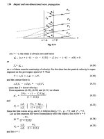
FLOTATION
AND
STABILITY
67
Figure
4.29 Modified
GZ
curve
other
side.
If
GGj
cos
<p
is
plotted
on the
stability
curve,
Figure
4.29,
for
the
particular
condition
of
loading
of the
ship,
the two
curves
intersect
at
B
and C. B
gives
the new
equilibrium
position
of the
ship
in
still
water
and
C
the new
angle
of
vanishing
stability.
The
range
of
stability
and the
maximum
righting
arm are
gready
reduced
on the
side
to
which
the
ship
lists.
For
heeling
to the
opposite
side
the
values
are
increased
but it is the
worse
case
that
is of
greater
concern
and
must
be
considered.
Clearly
every
precaution
should
be
taken
to
avoid
shifts
of
cargo.
Bulk
cargoes
A
related situation
can
occur
in the
carriage
of dry
bulk cargoes such
as
grain,
ore and
coal. Bulk cargoes settle down when
the
ship goes
to
sea so
that holds which were
full
initially, have void spaces
at the
top.
All
materials
of
this type have
an
angle
of
repose.
If the
ship rolls
to a
greater
angle than this
the
cargo
may
move
to one
side
and not
move back
later. Consequently
there
can be a
permanent transfer
of
weight
to one
side
resulting
in a
permanent list with
a
reduction
of
stability
on
that
side.
In the
past many ships have been lost
from
this cause.
Figure 4.30 shows
a
section through
the
hold
of a
ship carrying
a
bulk cargo. When
the
cargo setdes down
at sea its
centre
of
gravity
is at
g.
If the
ship rolls
the
cargo could take
up a new
position shown
by the
inclined line, causing some weight,
iu,
to
move horizontally
by
hi
and
vertically
by
h^.
As a
result
the
ship's
G
will
move:
The
modified righting
arm
becomes:
where
GZ is the
righting
arm
before
the
cargo
shifted.
68
FLOTATION
AND
STABILITY
Figure
4.30 Cargo
shift
Compared
with
the
stability
on
initial loading there
will
have been
a
slight
improvement
due to the
settling
of the
cargo.
Preventing
shift
of
bulk
cargoes
Regulations have existed
for
some time
to
minimize
the
movement
of
bulk
cargoes
and,
in
particular, grain. First, when
a
hold
is filled
with
grain
in
bulk
it
must
be
trimmed
so as to fill all the
spaces between
beams
and at the
ends
and
sides
of
holds.
Also
centreline bulkheads
and
shifting boards
are fitted in the
holds
to
restrict
the
movement
of
grain. They have
a
similar
effect
to
divisions
in
liquid carrying tanks
in
that they reduce
the
movement
of
cargo.
Centreline
bulkheads
and
shifting
boards were
at one time
required
to
extend
from
the
tank
top to the
lowest deck
in the
holds
and
from
deck
to
deck
in
'tween
deck spaces.
The
present
regulations
require that
the
shifting
boards
or
divisions extend downwards
from
the
underside
of
deck
or
hatch covers
to a
depth determined
by
calculations related
to
an
assumed heeling moment
of a filled
compartment.
The
centreline bulkheads
are fitted
clear
of the
hatches,
and are
usually
of
steel. Besides restricting cargo movement they
can act as a
line
of
pillars supporting
the
beams
if
they extend
from
the
tank
top to
the
deck. Shifting boards
are of
wood
and are
placed
on the
centreline
in
way of
hatches. They
can be
removed when
bulk
cargoes
are not
carried.
FLOTATION
AND
STABILITY
69
Even
with
centreline bulkheads
and
shifting
boards spaces
will
appear
at the top of the
cargo
as it
settles down.
To
help
fill
these
spaces
feeders
are fitted to
provide
a
head
of
grain which
will
feed into
the
empty
spaces. Hold feeders
are
usually formed
by
trunking
in
part
of
the
hatch
in the
'tween
decks above. Feeder capacity must
be 2 per
cent
of
the
volume
of the
space
it
feeds.
Precautions such
as
those outlined
above permit grain cargoes
to be
carried with
a
high
degree
of
safety.
DYNAMICAL
STABILITY
So
far
stability
has
been considered
as a
static problem.
In
reality
it is a
dynamic
one.
One
step
in the
dynamic examination
of
stability
is to
study
what
is
known
as a
ship's
dynamical
stability.
The
work done
in
heeling
a
ship through
an
angle
d<p
will
be
given
by the
product
of the
displacement,
GZ at the
instantaneous angle
and
d<p.
Thus
the
area
under
the GZ
curve,
up to a
given angle,
is
proportional
to the
energy
needed
to
heel
it to
that angle.
It is a
measure
of the
energy
it can
absorb
from
wind
and
waves
without heeling
too
far. This energy
is
solely
potential energy because
the
ship
is
assumed
to be
heeled
slowly.
In
practice
a
ship
can
have kinetic energy
of
roll
due to the
action
of
wind
and
waves.
This
is
considered
in the
next section.
Example
4.4
Using
the
tabulated values
of GZ
from
the
previous example,
determine
the
dynamical
stability
of the
vessel
at 60°
inclination.
Solution
The
dynamical stability
is
given
by:
This integral
can be
evaluated,
as in
Table 4.3, using Simpson's
1,4,1 rule
and the
ordinate
heights
from
Table 4.2,
The
area
under
the
curve
to 60°
Dynamical
stability
70
Table
4.3
FLOTATION
AND
STABILITY
Inclination
o
0
15
30
45
60
GZ
m
0
0.203
0.540
0.835
0.692
Simpson
's
multiplier
1
4
2
4
1
Sum
Area
product
0
0,812
1.080
3.340
0.692
mation
=
5.924
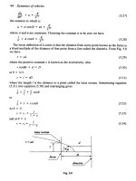
Influence
of
wind
on
stability
In
a
beam wind
the
force
generated
on the
above water surface
of
tJhe
ship
is
resisted
by the
hydrodynamic force
produced
by the
slow sideways
movement
of the
ship through
the
water.
The
wind force
may
be
taken
to
act
through
the
centroid
of the
above water
area
and the
hydrodynamic
force
as
acting
at
half
draught,
Figure
4.31.
For
ships
with
high freeboard
the
variation
of
wind
speed
with
height
may be
worth allowing
for
(see
Chapter
5).
For all
practical
purposes
the two
forces
can be
assumed
equal.
Let
the
vertical distance between
the
lines
of
action
of the two
forces
be h and the
projected area
of the
above water
form
be A, To
a first
order
as the
ship heels, both
h and A
will
be
reduced
in
proportion
to cos
<p.
Figure
431
Heeling
due to
wind
FLOTATION
AND
STABILITY
71
The
wind force will
be
proportional
to the
square
of the
wind
velocity,
V
w
,
and can be
written
as:
where
k is an
empirical constant.
The
moment
will
be:
The
curve
of
wind
moment
can be
plotted
with
the AGZ
curve
as in
Figure 4,32.
If the
wind moment builds
up or is
applied
slowly
the
ship
will
heel
to an
angle represented
by A and in
this condition
the
range
of
stability
will
be
from
A to
B.
The
problem would then
be
analogous
to
that
of the
shifted weight.
On the
other
hand,
if the
moment
is
applied suddenly,
say by a
gust
of
wind,
the
amount
of
energy applied
to the
ship
as it
heeled
to A
would
be
represented
by the
area
DAGO.
The
ship would only absorb energy represented
by
area
OAC and the
remaining energy would carry
it
beyond
A to
some angle
F
such that
area
AEF =
area DAO. Should
F be
beyond
B the
ship
will
capsize,
assuming
the
wind
is
still
acting.
Figure
4.32
A
severe case
for a
rolling ship
is if it is
inclined
to its
maximum angle
to
windward
and
about
to
return
to the
vertical when
the
gust hits
it.
Suppose
this position
is
represented
by GH in
Figure 4.32.
The
ship
would
already have
sufficient
energy
to
carry
it to
some angle past
the
upright,
say
KL
in the figure. Due to
damping this would
be
somewhat
less than
the
initial windward
angle.
The
energy
put
into
the
ship
by the
wind
up to
angle
L is now
represented
by the
area
GDKLOH.
The
ship
will
continue
to
heel until this energy
is
absorbed, perhaps reaching
angle
Q.
72
FLOTATION
AND
STABILITY
Angle
of
heel
due to
turning
When
a
ship
is
turning
under
the
action
of its
rudder,
the
rudder holds
the
hull
at an
angle
of
attack relative
to the
direction
of
advance.
The
hydrodynamic
force
on the
hull,
due to
this angle, acts towards
the
centre
of the
turning circle causing
the
ship
to
turn. Under
the
action
of
the
rudder
and
hull forces
the
ship
will
heel
to an
angle that
can be
determined
in a
similar
way to the
above.
STABILITY STANDARDS
It
has
been
demonstrated
how a
ship's transverse stability
can be
defined
and
calculated. Whilst
the
longitudinal stability
can be
evaluated according
to the
same principles,
it is not
critical
for
normal
ship
forms
as the
longitudinal stability
is so
much
greater
than
the
transverse. This
may not be
true
for
unconventional
forms
such
as
off-
shore
platforms.
The
stability
of
planing craft, hydrofoils
and
surface
effect
craft
also require special analysis because
the
forces supporting
the
weight
of the
craft,
which
will
determine their stability,
are at
least
partly
dynamic
in
origin.
In
what
follows
attention
is
focused
on
transverse
stability
of
intact conventional
monohulls.
Stability
in the
damaged state
will
be
dealt
with
later.
The
designer must decide very early
on in the
design process
what
level
of
stability needs
to be
provided. Clearly some stability
is
needed
or
else
the
ship
will
not float
upright,
but
loll
to one
side
or the
other.
In
theory
a
very
small positive
metacentric
height would
be
enough
to
avoid
this.
In
practice
more
is
needed
to
allow
for
differing
loading
conditions,
bad
weather, growth
in the
ship during service
and so on.
If
the
ship
is to
operate
in
very cold areas, allowance must
be
made
for
possible icing
up of
superstructure, masts
and
rigging.
The
designer, then, must decide
what
eventualities
to
allow
for in
designing
the
ship
and the
level
of
stability
needed
to
cope
with each.
Typically
modern ships
are
designed
to
cope
with:
(1)
the
action
of
winds,
up to say 100
kts;
(2)
the
action
of
waves
in
rolling
a
ship;
(3)
the
heel
generated
in a
high
speed
turn;
(4)
lifting
heavy
weights over
the
side, noting that
the
weight
is
effectively
acting
at the
point
of
suspension;
(5)
the
crowding
of
passengers
to one
side.
Standards
for USN
warships have been
stated
1
as
have
the
standards
adopted
by
Japan
2
and for
passenger
ships
3
.
These last
may be
summarized
as:
FLOTATION
AND
STABILITY
73
(1)
The
areas under
the
GZ
curve shall
not be
less than 0.055
m rad
up
to
30°;
not
less than
0.09m
rad up to 40° or up to the
downflooding
angle
and not
less than 0.03
m rad
between these
two
angles.
(2)
GZ
must
be
greater than
0.20m
at
30°.
(3)
Maximum
GZ
must occur
at an
angle
greater
than 30°.
(4)
Metacentric
height must
be at
least 0.15m.
Loading
conditions
Possible
loading
conditions
of a
ship
are
calculated
and
information
is
supplied
to the
master.
It is
usually
in the
form
of a
profile
of the
ship
indicating
the
positions
of all
loads
on
board,
a
statement
of the end
draughts,
the
trim
of the
ship
and the
metacentric
height. Stability
information
in the
form
of
curves
of
statical stability
is
often supplied.
The
usual loading conditions covered are:
(1)
the
lightship;
(2)
fully
loaded
departure
condition
with
homogeneous
cargo;
(3)
folly
loaded arrival condition
with
homogeneous cargo;
(4)
ballast condition;
(5)
other
likely
service conditions.
A
trim
and
stability
booklet
is
prepared
for the
ship showing
all
these
conditions
of
loading.
Nowadays
the
supply
of
much
of
this data
is
compulsory
and, indeed,
is one of the
conditions
for the
assignment
of
a
freeboard.
Other
data supplied
include
hydrostatics, cross curves
of
stability
and
plans
showing
the
position, capacity
and
position
of
centroids
for all
spaces
on
board. These
are to
help
the
master deal
with
non-standard
conditions.
FLOODING
AND
DAMAGED STABILITY
So
far
only
the
stability
of an
intact ship
has
been
considered.
In the
event
of
collision, grounding
or
just springing
a
leak, water
can
enter
the
ship.
If
unrestricted, this flooding would eventually cause
the
ship
to
founder, that
is
sink bodily,
or
capsize, that
is
turn over.
To
reduce
the
probability
of
this,
the
hull
is
divided into
a
series
of
watertight
compartments
by
means
of
bulkheads.
In
action, warships
are
expected
to
take punishment
from
the
enemy
so
damage stability
is
clearly
an
important consideration
in
their design. However, damage
is a
possibility
for any
ship.
74
FLOTATION
AND
STABILITY
Bulkheads cannot ensure complete
safety
in the
event
of
damage.
If
the
hull
is
opened
up
over
a
sufficient
length several compartments
can
be flooded.
This
was the
case
in the
tragedy
of the
Titanic.
Any flooding
can
cause
a
reduction
in
stability
and if
this reduction becomes
great
enough
the
ship
will
capsize.
Even
if the
reduction does
not
cause
capsize
it may
lead
to an
angle
of
heel
at
which
it is
difficult,
or
impossible,
to
launch lifeboats.
The
losses
of
buoyancy
and
stability
due
to flooding are
considered
in the
following sections.
Sinkage
and
trim
when
a
compartment
is
open
to the sea
Suppose
a
forward compartment
is
open
to the
sea, Figure 4.33.
The
buoyancy
of the
ship between
the
containing bulkheads
is
lost
and the
ship
settles
in the
water until
it
picks
up
enough buoyancy
from
the
rest
of
the
ship
to
restore equilibrium.
At the
same time
the
position
of the
LCB
moves
and the
ship must trim until
G and B are
again
in a
vertical
line.
The
ship which
was
originally
floating at
waterline
W
0
Lo
now floats
at
Wi
Lj
.
Should
Wj
LI
be
higher
at any
point than
the
deck
at
which
the
bulkheads stop (the
bulkhead
deck}
it is
usually assumed that
the
ship
would
be
lost
as a
result
of the
water pressure
in the
damaged
compartment forcing
off the
hatches
and
leading
to
unrestricted
flooding
fore
and
aft.
In
practice
the
ship might still remain
afloat
for
a
considerable time.
Figure
4.33 Compartment open
to the sea
Most
compartments
in a
ship contain items which
will
reduce
the
volume
of
water that
can
enter. Even
'empty'
spaces usually have frames
or
beams
in
them.
At the
other
extreme some spaces
may
already
be
full
of
ballast water
or
fuel.
The
ratio
of the
volume that
is
floodable
to the
total
volume
is
called
the
permeability
of the
space. Formulae
for
calculating
permeabilities
for
merchant
ships
are
laid down
in the
Merchant Ship (Construction) Rules. Typical values
are
presented
in
Table 4.4. Although
not
strictly accurate,
the
same values
of
permeabil-
ity
are
usually
applied
as
factors when assessing
the
area
and
inertias
of
the
waterplane
in way of
damage.