The gauge block handbook Episode 8 docx
Bạn đang xem bản rút gọn của tài liệu. Xem và tải ngay bản đầy đủ của tài liệu tại đây (217.4 KB, 14 trang )
99
As aperture diameter approaches zero, the correction approaches zero. The correction is very small
when using a laser because the beam diameter is small at the aperture.
6.2.5 Laser Light Sources
The advantage of a laser light source lies in its unequalled coherence. Conventional spectral light
sources have such low coherence that blocks longer than 300 mm have, in the past, been measured
by stepping up from shorter blocks. Laser fringe patterns in these interferometers compared with
patterns from other spectral lamps are of superior contrast and definition through the length range 0
to 500 mm.
The disadvantage stems from the somewhat unstable wavelength of lasers. This problem has been
overcome by a number of different stabilization schemes, and by using the .6328 µm line of HeNe
lasers. These lasers can be related to the definition of the meter by calibration against an iodine
stabilized HeNe laser [41,42]. The wavelength of the iodine stabilized laser is known to a few parts
in 10
9
and is one of the recommended sources for realizing the meter [8]. The lasers currently used
for gauge block calibration are polarization stabilized [43].
Single wavelength static interferometry, in contrast with multiple wavelength interferometry,
requires that the gauge block length be known to within 0.25 wavelength (0.5 fringe) either from its
history or from another measurement process. This is no problem for NIST reference blocks, or for
blocks calibrated by the NIST mechanical comparison technique.
Laser light must not be allowed to reflect back into its own cavity from the interferometer optical
components because this will disturb the lasing action and may cause a wavelength shift, wavelength
jittering or it may stop the lasing altogether. The reflected light is prevented from re-entering the
laser by a polarization isolator consisting of a Glan Thompson prism and a quarter wave plate in the
beam as it emerges from the cavity. This assembly is tilted just enough to deflect reflections from its
faces to the side of the laser exit aperture.
6.3 Environmental Conditions and their Measurement
Environmental control of the laboratory holds temperature at 20.05 ºC and water vapor content
below 50% relative humidity. Temperature variations within the insulated interferometer housing
are attenuated by a factor of about 10 from those in the room, thus insuring stability of both
interferometer and blocks.
Temperature, atmospheric pressure, and water vapor content of the ambient air in the interferometer
light path must be measured at the time the gauge block is measured. From these properties the
refractive index of the air is calculated, and in turn, the laser wavelength. Since interferometry is a
comparison of the light wavelength to the block length the accuracy of the wavelength is of primary
importance. The gauge block temperature is measured so that the block length at 20 ºC, the standard
100
temperature for dimensional metrology, can be computed.
6.3.1 Temperature
The measuring system accuracy for air and block temperature depends on the length of the gauge
block to be measured. Since both the wavelength and block temperature corrections are length
dependent, a 500 mm measurement must have correction factors 10 times as good as those for a 50
mm measurement to achieve the same calibration accuracy,
For blocks measured with the NPL interferometer (less than 100 mm) a calibrated thermistor probe
is used to measure temperature to an accuracy of 0.01 ºC and a calibrated aneroid barometer is used
to measure atmospheric pressure to 0.1 mm of mercury.
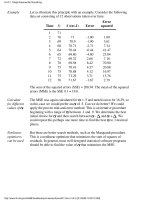
For long blocks the system is much more complicated. The measuring system for air and block
temperature consists of copper-constantan thermocouples referenced to a platinum resistance
thermometer. Figure 6.7 is a schematic diagram of the system.
A solid copper cube provides a stable reference temperature measured by a Standard Platinum
Resistance Thermometer (SPRT) and a Mueller resistance bridge. A well in the cube holds the
thermometer stem, the reference thermocouple junction, and a liquid of high heat conductivity but
low electrical conductivity. There is also a second well whose function will be described later. An
enclosed thermocouple selector switch connects the measuring junctions, one at a time, to the
reference junction and the thermal emfs generated by the temperature differences between measuring
junction and reference junction are indicated on a nanovoltmeter. The nanovoltmeter is shared with
the bridge where it is used as a nullmeter. To keep the copper block in a stable state and to minimize
thermal emfs in the selector switch, both block and switch are enclosed in an insulated box. The
switch is operated through a fiber shaft extending to the exterior and the protruding part of the
thermometer is protected by an insulated tube.
Figure 6.7 The temperature measurement system used for gauge block calibration
consists of multiple thermocouples referenced to a calibrated platinum resistance
thermometer.
PLATINUM RESISTANCE
THERMOMETER
REFERENCE
THERMOCOUPLE
JUNCTION
MEASURING
THERMOCOUPLE
JUNCTIONS
DPDT SWITCH
RESISTANCE
THERMOMETER
BRIDGE
NANO-
VOLTMETER REFERENCE
TEMPERATURE
THERMOCOUPLE
SELECTOR
SWITCH
101
Thermocouples generate emfs proportional to the temperature gradient along the wire:
(6.9)
where T
1
and T
2
are the temperatures of the reference and measuring junctions respectively, and φ is
the thermocouple constant. Minimizing this gradient reduces uncertainties.
Relating the system to the International Temperature Scale of 1990 (ITS '90) is a three step
procedure. First, the SPRT is calibrated using methods described in NIST Technical Note 1265
[44]. Second, the bridge is calibrated as described the same monograph. The third step is the
calibration of the thermocouples, which is accomplished with a second SPRT and insulated copper
cube. The second cube has an extra well for the thermocouples being calibrated and is heated one or
two degrees to equilibrium. Measured thermal emfs generated by the temperature difference
between the two cubes together with the temperatures of the cubes allow computation of a
calibration factor for each junction.
Integrity is maintained by periodic check of the SPRT with a triple point cell, checking the bridge
against a calibrated resistor and checking the thermocouples for equality when they are all at the
same temperature in a well of an insulated copper cube.
6.3.2 Atmospheric Pressure
The interferometer housing is not airtight and pressure inside it is the same as laboratory pressure.
An aneroid barometer is located adjacent to and at the same elevation as the interferometer. The
aneroid used for gauge block measurements has good stability, and frequent comparisons with NIST
reference barometers insure its reliability.
For long blocks more precise measurement of the pressure is useful. There are a number of
commercially available atmospheric pressure sensors available which are of adequate accuracy for
gauge block calibration. Remembering that measurements to one part in 10
7
requires pressure
measurement accuracy of .3mm of Hg, a calibrated aneroid barometer can be adequate. For systems
requiring automatic reading of pressure by a computer there are a number of barometers which use
capacitance or vibrating cylinders to measure pressure and have RS-232 or IEEE 488 interfaces.
6.3.3 Water Vapor
The humidity is derived from a chilled mirror dew point hygrometer. The system is calibrated by the
NIST humidity calibration service and is accurate to about 1% R.H. Other systems have adequate
accuracy but need more frequent checking for drift. The disadvantage of the chilled mirror is that it
requires a specified air flow rate not usually available inside an interferometer. Humidity inside an
interferometer enclosure may differ from the laboratory value by as much as 6% R.H., especially
dT = E
T
T
1
2
φ
∫
102
during periods of changing laboratory humidity. If this presents a serious problem (see table 6.1)
then a hygrometer type less dependent on air flow rate must be mounted inside the interferometer.
6.4 Gauge Block Measurement Procedure
In preparation for measurement, the gauging faces of the NIST standards are cleaned with ethyl
alcohol. Wiping the alcohol-rinsed gauging faces is done with paper tissue or a clean cotton towel.
Lint or dust is removed with a camel's hair brush.
The gauging faces are examined for burrs and, if present, these are removed with a deburring stone.
The bottom end is tested for wringability with a quartz optical flat. The transparency of the flat
makes possible a judgment of the wring. A uniform grey color at the interface indicates a good
wring. Any colored or light areas indicate a gap of more than 25 nm between the faces in that area,
and such a gap may result in an erroneous length measurement. Deburring and cleaning is continued
until a good wring is achieved. The quartz flat is left wrung to the gauging face to keep it clean until
preparations are completed for wringing the block to the steel optical flat (platen).
Preparation of the steel platen is similar. Ethyl alcohol is used to rinse the face, then deburring if
necessary, followed by more rinsing and drying. After sweeping with a camel hair brush, a thin
uniform film of light grease is applied to the wringing surface with a bit of tissue. This film is
rubbed and finally polished with tissue or towel until the film appears to be gone. After carefully
sweeping the platen with a brush, it is ready for wringing.
The block is removed from the quartz flat and the exposed gauging face is immediately wrung by
carefully sliding it onto the edge of the platen, maintaining perpendicularity by feel. Sliding is
continued until wringing resistance is felt, and then with slight downward pressure the block is
slowly worked into its final position. Square style blocks, such as the NIST long blocks, are
positioned so that the gauge point is at the right in the viewing field of the interferometer. One to
four blocks can be wrung to the platens used in the Kosters interferometer. Ten square blocks or 20
rectangular blocks can be wrung onto the platens at one time for use in the NPL interferometer.
For long blocks measured in the Kosters interferometer, the platen with its wrung blocks is placed in
the interferometer and two thermocouples are fed down the center hole of each block, one about
three quarters down and one about one quarter down the length of the block. A small wad of
polyurethane is pushed into the hole to seal and hold the wires. For small blocks, where there can be
no significant vertical thermal gradient, the temperature sensor is attached to the platen.
A preliminary alignment by autocollimation with the Gaussian eyepiece as the support table is
adjusted, will produce fringes. Rapid changes in the fringe pattern occur as the blocks and platen
cool from handling.
It is convenient to wring the blocks in late afternoon and allow overnight temperature stabilization.
Two length observations are made several hours apart, but the first measurement is not taken until
the laser is in equilibrium. Leaving the laser on continuously when observations are being made
over several days eliminates delays.
103
Final fringe pattern adjustment is made so that the platen fringes are parallel to the top and bottom
edges of the block and one fringe on the block goes through its defined gauge point. For the Kosters
interferometer the direction of increasing fringe order is verified by pressing down on the eyepiece
and observing the fringe movement. In the NPL, the reference mirror is pushed and the fringe
movement is observed. The fringe fraction can be estimated by eye or a photograph can be taken of
the pattern. Block temperature, air temperature, barometric pressure, and humidity are measured
immediately before and after the observation and then averaged.
The photograph can be either a positive or a negative. A compromise is made between image size
and exposure time, but short exposure is desirable because the fringe pattern may shift during a long
exposure. Further image magnification takes place in the fringe measuring instrument. A
compromise is also made between magnification in the photograph and magnification in the
instrument used to measure the photograph. Too much total magnification degrades image
sharpness, making fringe measurements more difficult.
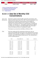
Fringe fractions are obtained from the photograph with a coordinate comparator having a fixed stage
in the focal plane of a microscope movable on X-Y slides by precision screws with drum readouts.
Four measurements of distance "a" and "b" are recorded and averaged to obtain fringe fraction f, as
shown in figure 6.8.
Figure 6.8. The fringe fraction is the fractional offset of the fringes on the block
from those of the platen.
Settings on the block fringe to obtain "a" are made at the point where the fringe intersects the gauge
point. Settings on the platen fringes to obtain "a" and "b" are made as close as practical to the edges
of the block because it is here that the platen best represents an extension of the bottom face of the
block. Parallelism between gauge block and platen is also read from the photo because this
104
information is useful in detecting a defective wring. Poor wringing contact is indicated if the
parallelism is different from its usual value (or mechanically determined value using the comparator)
and this is sufficient cause to discard a particular length measurement.
Photographing fringe patterns has several advantages. The photograph is a permanent record that
can be reinterpreted at any time with the same or other techniques. Changes in block geometry are
readily seen by comparing photographs in time sequence. The coordinate comparator is superior to
the common practice of fringe fraction estimation by eye because it is more objective, lends itself to
multiple measurements and averaging, and is more precise. Finally, photography is fast and thus
permits readings of the ambient conditions to closely bracket the fringe recording. This is especially
important because atmospheric pressure is generally not constant.
The advent of computer vision systems provides another method of recording and analyzing fringes.
There are commercially available software packages for measuring fringe fractions that can be
incorporated into an automated gauge block measuring system.
6.5 Computation of Gauge Block Length
Calculating gauge block length from the data is done in 3 steps:
1. Calculation of wavelength, λ
tpf
, at observed ambient conditions.
2. Calculation of the whole number of fringes in the gauge block length from its predicted
length and the laser wavelength in ambient air.
3. Calculation of the gauge block length from the whole number of fringes, the observed
fraction, wavelength in ambient air, gauge block temperature, and interferometric correction
factors.
6.5.1 Calculation of the Wavelength
Edlen's 1966 formula [45] for the refractive index of air is used to calculate the wavelength.
Comparison of absolute refractometers showed that the Edlen equation agreed with refractometers as
well as the refractometers agreed with each other, to about 1 part in 10
7
[46]. More recent work by
Birch and Downs [47] has shown that the original data used for the water vapor correction was
slightly in error. The new correction (the parameter C below) is thought to increase the accuracy of
the Edlen formula to about 3x10
-8
. This latter figure can be taken as an estimate of the accuracy of
the formula.
The latest revision of the Edlen formula is [48]:
λ
0
= n
tpf
λ
tpf
(6.10)
105
and thus
λ
0
λ
tpf
= = λ
0
[1 + A*B - C]
-1
(6.11)
n
tpf
where
A = p[8342.22 + 2406057(130-σ
2
)
-1
+ 15997 (38.9-σ
2
)
-1
] 10
-8
(6.12)
96095.43
B = 1 + p (0.601-0.00972t) 10
-6
(6.13)
1+0.003661t
C = f (3.7345-0.0401σ
2
) 10
-8
. (6.14)
The symbols used are:
λ
0
= Vacuum wavelength in µm
λ
ptf
= Wavelength at observed conditions t,p,f
n
ptf
= Index of refraction of air at t,p,f
p = Atmospheric pressure in Pa
t = Temperature in degrees Celsius
f = water vapor pressure in Pa
σ = 1/λ
0
in µm.
6.5.2 Calculation of the Whole Number of Fringes
This method for determining the whole number of fringes is valid if the block length is known to
better than 0.5 fringe ( 1 fringe is about 0.32 µm for helium neon laser light) from either its history
or from an independent measurement process. The calculation is as follows:
2L
p
[1+C(t'-20)]
F = (6.15)
λ
tpf
106
where F is the number of interference fringes in the length of the block at temperature t', and
in air of temperature t, pressure p, and vapor pressure f.
L
p
is the predicted block length at 20 ºC taken from its history or an independent
measurement.
C is the linear thermal expansion coefficient per degree Celsius of the block.
t' is the block temperature at the time of measurement.
λ
tpf
is the wavelength in the ambient air at the time of measurement.
The fractional part of F is retained temporarily for the reasons explained below.
6.5.3 Calculation of Block Length from the Observed Data
Generally, the observed fringe fraction φ is simply substituted for the fractional part of F, but there
are cases where the last digit in whole number F must be raised or lowered by one. For example if
the fractional part of F is 0.98 and the observed fraction is 0.03, obviously, the last whole number in
F must be raised by one before substituting the observed fraction.
The new measured block value, in fringes, is
F' = F + φ. (6.16)
Finally, the interferometer aperture correction, δ
2
, is added, the block is normalized to 20 ºC, and a
conversion to length units is made to arrive at the final value at 20 ºC as follows:
λ
tpf
L
20
= F'[1+C(20-t')] + δ
2
. (6.17)
2
107
6.6 Type A and B Errors
Potential sources of errors are as follows:
1. Wavelength
a. Vacuum wavelength of laser
b. Refractive index of air equation
c. Refractive index determination
Air temperature measurement
Atmospheric pressure measurement
Humidity measurement
2. Interferometer
a. Alignment
b. Aperture correction
c. Obliquity correction
3. Gauge Block
a. Gauge block temperature measurement
b. Thermal expansion coefficient
c. Phase shift difference between block and platen
Length proportional errors are potentially the most serious in long block measurement. Their
relative influence is illustrated in table 10. One example will help explain the table: if air
temperature measurement is in error by 0.1 ºC a systematic error of 1 part in 10
7
results. For a 250
mm gauge block the error is 25 nm, a significant error. On a 10 mm gauge block the same
temperature measurement leads to only a 1 nm error, which is negligible.
In our measurement process every practical means, as previously discussed, was used to reduce
these errors to a minimum and, at worst, errors in measuring the parameters listed above do not
exceed those listed in table 10. Further evaluation of these errors is described in section 4.3 on
process control and our master block history.
A few sources of error in the list of systematic errors but not in the table have not been completely
discussed. The first of these is phase shift difference between block and platen. When light is
reflected from a surface the phase of the reflected light is shifted from the phase of the incident by
some amount which is characteristic of the surface's material composition and surface finish. The
explanation and measurement of phase is given in appendix C. Most gauge blocks have phase shifts
that differ from quartz by an equivalent of 25 to 75 nm. This is a large source of error, although if
both the block and platen are made of the same metal the error is reduced below 20 nm. Since the
phase shift occurs only at the metal surface it is not length dependent.
108
Table 10
Effects of Environmental Factor Errors on Length
Parameter Change Which Leads to a Length
Error of 1 part in 10
7
Wavelength
Vacuum wavelength 1 part in 10
7
Refractive index formula 1 part in 10
7
Air temperature 0.1ºC
Atmospheric Pressure 40 pa
Relative Humidity 12% R.H.
Interferometer Alignment 0.45 mm/m
Gauge Block
Steel gauge block temperature 0.009 ºC
Chrome Carbide block temp. 0.012 degc
Thermal expansion coefficients of gauge blocks have an uncertainty that is, to a large extent,
nullified by measuring at temperatures very close to the 20 ºC reporting temperature. Gauge block
manufacturers give 11.5 x 10
-6
/ºC for steel blocks. This average value may be uncertain by up to 0.6
x 10
-6
/ºC for individual blocks. The expansion coefficient for steel blocks is also length dependent
for long blocks, as discussed earlier in section 3.3. The expansion coefficient for longer sizes can
differ from the nominal 11.5 x 10
-6
/ºC by nearly 1 x 10
-6
/ºC. These uncertainties can cause
significant errors if blocks are used at other than 20 ºC.
There are, of course, random errors that arise from variability in any parameter in the table, and in
addition, they can arise in the fringe fraction measurement and wringing variability. Wringing is
discussed in more detail in appendix B. Gauge blocks are generally measured for 3 to 5 separate
wrings to sample variability due to these sources.
109
6.7 Process Evaluation
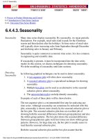
Figure 6.9 shows some examples of the interferometric history of NIST master gauge blocks. As
expected, the scatter in the data is larger for longer blocks because of the uncertainties in the length
dependent thermal expansion and index of refraction corrections.
Figure 6.9. Examples of the interferometric history of NIST master gauge blocks.
The length dependence of the variability is shown graphically in figure 6.10. This variability has
two components: (1) non-length related variabilitys due to variations in the wringing film between
the block and the platen, and random errors in reading the fringes; and (2) a length dependent part
primarily due to environmental effects.
ID: F15 Size: 25 mm 15 Pts. Avg. = 0.018
Nominal Deviation (micrometers)
ID: 5 83 Size: 0.1 inch 56 Pts. Avg. = 0.296
Deviation in micrometers
Deviation in microinches
110
Figure 6.10. The variability (σ) of NIST master gauge blocks as a function of length.
The major components of the interferometric measurement uncertainty are shown in table 6.2. The
errors can be divided into two classes: those which are correlated ( the same for all measurements)
and those which are uncorrelated (vary for each measurement). The classification depends on the
measurement history. NIST gauge blocks which are measured over a long period of time, during
which the thermometers and barometers are recalibrated. In this case the errors due to thermal
expansion and refractive index corrections vary. For a customer block, measured 4 times over a 4
day period, they do not vary. Table 6.2 classifies the errors for both NIST masters and customer
calibrations.
Microinches
Nanometers
Nominal Length (inches)
111
Table 6.2
Uncertainty Uncertainty
Source of Uncertainty
Type for NIST Masters Type for Customers
Reading error uncorrelated uncorrelated
Obliquity/Slit Correction correlated correlated
Wringing Film Thickness uncorrelated uncorrelated
Phase Correction correlated correlated
Thermal Expansion Correction
Temperature Measurement uncorrelated correlated
Expansion Coefficient Value correlated correlated
Index of Refraction
Edlén Equation correlated correlated
Environmental Measurements uncorrelated uncorrelated
Laser Frequency uncorrelated correlated
The interferometric history provides a statistical sample of all of the uncorrelated errors. Using the
information from figure 6.10 we obtain an estimate of the uncorrelated errors to be:
U
u
(µm) ~ 0.008 + 0.03 x L (L in meters) (6.20)
Multiple measurements of a gauge block can reduce this figure; if n measurements are made the
uncertainty of the average length becomes U
u
/n. Unfortunately, the correlated errors are not
sampled by repeated measurements and are not reduced by multiple measurements. An estimate of
the correlated uncertainties for NIST master gauge block calibrations is:
U
c
(µm) ~ 0.007 + 0.07 x L (L in meters) (6.21)
Because customer blocks have more correlated errors and more importantly do not have measured
thermal expansion coefficients, the use of multiple measurements is less effective in reducing
measurement uncertainty. For most customers, interferometric measurements are not cost-effective
since the uncertainty for a three wring interferometric measurement is not significantly lower than
the mechanical comparison measurement, but costs twice as much. If, however, a customer sends in
the same blocks for interferometric measurement over a number of years and uses the accumulated
history then the uncertainty of the blocks will approach that of NIST master blocks.
112
6.8 Multiple wavelength interferometry
If we think of gauge block interferometry as the measurement of height with a ruler marked in units
of λ/2, we quickly realize that our ruler has units unlike a normal ruler. The lines which show a
distance of λ/2 are there but there are no numbers to tell us which mark we are looking at. This ruler
can be used if we know the length of the block to better than λ/4 since we can use this distance and
make the small correction (less than λ/4) found by interpolating between the lines on our scale.
Suppose, however, we do not know the length this well ahead of time.
The correct method in this case is to use a number of rulers with different and incommensurate
scales. In interferometry we can use several light sources ranging from blue to red to provide these
different scales. A simple example is shown in figure 6.11.
Figure 6.11. Four color interferometry is equivalent to measuring a
length with four scales of known pitch which have indeterminate
zeros.
For each scale (color) there will be a fringe fraction f
i
. With only one color the block might have
any length satisfying the formula:
f = 0 f = .71 f = .87 f = .62
λ
/
2
= 10 = 17 = 23 = 29
λ
/
2
λ
/
2
λ
/
2