gdi programming with c sharp phần 8 ppsx
Bạn đang xem bản rút gọn của tài liệu. Xem và tải ngay bản đầy đủ của tài liệu tại đây (4.07 MB, 70 trang )
[ Team LiB ]
This document was created by an unregistered ChmMagic, please go to to register it. Thanks.
[ Team LiB ]
This document was created by an unregistered ChmMagic, please go to to register it. Thanks.
10.4 The Graphics Class and Transformation
In Chapter 3 we saw that the Graphics class provides some transformation-related members. Before we move to other transformation-related
classes, let's review the transformation functionality defined in the Graphics class, as described in Table 10.2. We will see how to use these
members in the examples throughout this chapter.
The Transform property of the Graphics class represents the world transformation of a Graphics object. It is applied to all items of the object.
For example, if you have a rectangle, an ellipse, and a line and set the Transform property of the Graphics object, it will be applied to all three
items. The Transform property is a Matrix object. The following code snippet creates a Matrix object and sets the Transform property:
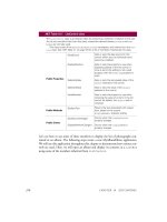
Table 10.2. Transformation-related members defined in the Graphics class
MemberDescription
MultiplyTransform
Method that multiplies the world transformation of a Graphics object and a Matrix object. The Matrix object specifies
the transformation action (scaling, rotation, or translation).
ResetTransform
Method that resets the world transformation matrix of a Graphics object to the identity matrix.
RotateTransform
Method that applies a specified rotation to the transformation matrix of a Graphics object.
ScaleTransform
Method that applies a specified scaling operation to the transformation matrix of a Graphics object by prepending it
to the object's transformation matrix.
Transform
Property that represents the world transformation for a Graphics object. Both get and set.
TransformPoints
Method that transforms an array of points from one coordinate space to another using the current world and page
transformations of a Graphics object.
TranslateClip
Method that translates the clipping region of a Graphics object by specified amounts in the horizontal and vertical
directions.
TranslateTransform
Method that prepends the specified translation to the transformation matrix of a Graphics object.
Matrix X = new Matrix();
X.Scale(2, 2, MatrixOrder.Append);
g.Transform = X;
The transformation methods provided by the Graphics class are MultiplyTransform, ResetTransform, RotateTransform, ScaleTransform,
TransformPoints, TranslateClip, and TranslateTransform. The MultiplyTransform method multiplies a transformation matrix by the world
transformation coordinates of a Graphics object. It takes an argument of Matrix type. The second argument, which specifies the order of
multiplication operation, is optional. The following code snippet creates a Matrix object with the Translate transformation. The
MultiplyTransform method multiplies the Matrix object by the world coordinates of the Graphics object, translating all graphics items drawn by
the Graphics object.
Matrix X = new Matrix();
X. Translate(200.0F, 100.0F);
This document was created by an unregistered ChmMagic, please go to to register it. Thanks.
g.MultiplyTransform(X, MatrixOrder.Append);
RotateTransform rotates the world transform by a specified angle. This method takes a floating point argument, which represents the rotation
angle, and an optional second argument of MatrixOrder. The following code snippet rotates the world transformation of the Graphics object by
45 degrees:
g.RotateTransform(45.0F, MatrixOrder.Append);
The ScaleTransform method scales the world transformation in the specified x- and y-directions. The first and second arguments of this
method are x- and y-direction scaling factors, and the third optional argument is MatrixOrder. The following code snippet scales the world
transformation by 2 in the x-direction and by 3 in the y-direction:
g.ScaleTransform(2.0F, 3.0F, MatrixOrder.Append);
The TranslateClip method translates the clipping region in the horizontal and vertical directions. The first argument of this method represents
the translation in the x-direction, and the second argument represents the translation in the y-direction:
e.Graphics.TranslateClip(20.0f, 10.0f);
The TranslateTransform method translates the world transformation by the specified x- and y-values and takes an optional third argument of
MatrixOrder:
g.TranslateTransform(100.0F, 0.0F, MatrixOrder.Append);
We will use all of these methods in our examples.
[ Team LiB ]
This document was created by an unregistered ChmMagic, please go to to register it. Thanks.
[ Team LiB ]
10.5 Global, Local, and Composite Transformations
Transformations can be divided into two categories based on their scope: global and local. In addition, there are composite transformations. A
global transformation is applicable to all items of a Graphics object. The Transform property of the Graphics class is used to set global
transformations.
A composite transformation is a sequence of transformations. For example, scaling followed by translation and rotation is a composite
translation. The MultiplyTransform, RotateTransform, ScaleTransform, and TranslateTransform methods are used to generate composite
transformations.
Listing 10.14 draws two ellipses and a rectangle, then calls ScaleTransform, TranslateTransform, and RotateTransform (a composite
transformation). The items are drawn again after the composite transformation.
Listing 10.14 Applying a composite transformation
private void GlobalTransformation_Click(object sender,
System.EventArgs e)
{
// Create a Graphics object
Graphics g = this.CreateGraphics();
g.Clear(this.BackColor);
// Create a blue pen with width of 2
Pen bluePen = new Pen(Color.Blue, 2);
Point pt1 = new Point(10, 10);
Point pt2 = new Point(20, 20);
Color [] lnColors = {Color.Black, Color.Red};
Rectangle rect1 = new Rectangle(10, 10, 15, 15);
// Create two linear gradient brushes
LinearGradientBrush lgBrush1 = new LinearGradientBrush
(rect1, Color.Blue, Color.Green,
LinearGradientMode.BackwardDiagonal);
LinearGradientBrush lgBrush = new LinearGradientBrush
(pt1, pt2, Color.Red, Color.Green);
// Set linear colors
lgBrush.LinearColors = lnColors;
// Set gamma correction
lgBrush.GammaCorrection = true;
// Fill and draw rectangle and ellipses
g.FillRectangle(lgBrush, 150, 0, 50, 100);
g.DrawEllipse(bluePen, 0, 0, 100, 50);
g.FillEllipse(lgBrush1, 300, 0, 100, 100);
// Apply scale transformation
g.ScaleTransform(1, 0.5f);
// Apply translate transformation
g.TranslateTransform(50, 0, MatrixOrder.Append);
// Apply rotate transformation
g.RotateTransform(30.0f, MatrixOrder.Append);
// Fill ellipse
This document was created by an unregistered ChmMagic, please go to to register it. Thanks.
g.FillEllipse(lgBrush1, 300, 0, 100, 100);
// Rotate again
g.RotateTransform(15.0f, MatrixOrder.Append);
// Fill rectangle
g.FillRectangle(lgBrush, 150, 0, 50, 100);
// Rotate again
g.RotateTransform(15.0f, MatrixOrder.Append);
// Draw ellipse
g.DrawEllipse(bluePen, 0, 0, 100, 50);
// Dispose of objects
lgBrush1.Dispose();
lgBrush.Dispose();
bluePen.Dispose();
g.Dispose();
}
Figure 10.15 shows the output from Listing 10.14.
Figure 10.15. Composite transformation
A local transformation is applicable to only a specific item of a Graphics object. The best example of local transformation is transforming a
graphics path. The Translate method of the GraphicsPath class translates only the items of a graphics path. Listing 10.15 translates a graphics
path. We create a Matrix object and apply rotate and translate transformations to it.
Listing 10.15 Translating graphics path items
private void LocalTransformation_Click(object sender,
System.EventArgs e)
This document was created by an unregistered ChmMagic, please go to to register it. Thanks.
{
// Create a Graphics object
Graphics g = this.CreateGraphics();
g.Clear(this.BackColor);
// Create a GraphicsPath object
GraphicsPath path = new GraphicsPath();
// Add an ellipse and a line to the
// graphics path
path.AddEllipse(50, 50, 100, 150);
path.AddLine(20, 20, 200, 20);
// Create a blue pen with a width of 2
Pen bluePen = new Pen(Color.Blue, 2);
// Create a Matrix object
Matrix X = new Matrix();
// Rotate 30 degrees
X.Rotate(30);
// Translate with 50 offset in x direction
X.Translate(50.0f, 0);
// Apply transformation on the path
path.Transform(X);
// Draw a rectangle, a line, and the path
g.DrawRectangle(Pens.Green, 200, 50, 100, 100);
g.DrawLine(Pens.Green, 30, 20, 200, 20);
g.DrawPath(bluePen, path);
// Dispose of objects
bluePen.Dispose();
path.Dispose();
g.Dispose();
}
Figure 10.16 shows the output from Listing 10.15. The transformation affects only graphics path items (the ellipse and the blue [dark] line).
Figure 10.16. Local transformation
This document was created by an unregistered ChmMagic, please go to to register it. Thanks.
[ Team LiB ]
This document was created by an unregistered ChmMagic, please go to to register it. Thanks.
[ Team LiB ]
10.6 Image Transformation
Image transformation is exactly the same as any other transformation process. In this section we will see how to rotate, scale, translate,
reflect, and shear images. We will create a Matrix object, set the transformation process by calling its methods, set the Matrix object as the
Transform property or the transformation methods of the Graphics object, and call DrawImage.
Rotating images is similar to rotating other graphics. Listing 10.16 rotates an image. We create a Graphics object using the CreateGraphics
method. Then we create a Bitmap object from a file and call the DrawImage method, which draws the image on the form. After that we create a
Matrix object, call its Rotate method, rotate the image by 30 degrees, and apply the resulting matrix to the surface using the Transform property.
Finally, we draw the image again using DrawImage.
Listing 10.16 Rotating images
private void RotationMenu_Click(object sender,
System.EventArgs e)
{
Graphics g = this.CreateGraphics();
g.Clear(this.BackColor);
Bitmap curBitmap = new Bitmap(@"roses.jpg");
g.DrawImage(curBitmap, 0, 0, 200, 200);
// Create a Matrix object, call its Rotate method,
// and set it as Graphics.Transform
Matrix X = new Matrix();
X.Rotate(30);
g.Transform = X;
// Draw image
g.DrawImage(curBitmap,
new Rectangle(205, 0, 200, 200),
0, 0, curBitmap.Width,
curBitmap.Height,
GraphicsUnit.Pixel) ;
// Dispose of objects
curBitmap.Dispose();
g.Dispose();
}
Figure 10.17 shows the output from Listing 10.16. The first image is the original; the second image is rotated.
Figure 10.17. Rotating images
This document was created by an unregistered ChmMagic, please go to to register it. Thanks.
Now let's apply other transformations. Replacing the Rotate method in Listing 10.16 with the following line scales the image:
X.Scale(2, 1, MatrixOrder.Append);
The scaled image is shown in Figure 10.18.
Figure 10.18. Scaling images
This document was created by an unregistered ChmMagic, please go to to register it. Thanks.
Replacing the Rotate method in Listing 10.16 with the following line translates the image with 100 offset in the x- and y-directions:
X.Translate(100, 100);
The new output is shown in Figure 10.19.
Figure 10.19. Translating images
Replacing the Rotate method in Listing 10.16 with the following line shears the image:
X.Shear(2, 1);
The new output is shown in Figure 10.20.
Figure 10.20. Shearing images
This document was created by an unregistered ChmMagic, please go to to register it. Thanks.
You have probably noticed that image transformation is really no different from the transformation of other graphics objects. We recommend
that you download the source code samples from online to see the detailed code listings.
[ Team LiB ]
This document was created by an unregistered ChmMagic, please go to to register it. Thanks.
[ Team LiB ]
10.7 Color Transformation and the Color Matrix
So far we have seen the transformation of graphics shapes from one state to another, but have you ever thought about transforming colors?
Why would you want to transform an image's colors? Suppose you wanted to provide grayscale effects, or needed to adjust the contrast,
brightness, or even "redness" of an image. For example, images retrieved from video and still cameras often need correction. In these cases,
a color matrix is very useful.
As we discussed in earlier chapters, the color of each pixel of a GDI+ image or bitmap is represented by a 32-bit number, of which 8 bits each
are used for the red, green, blue, and alpha components. Each of the four components is a number from 0 to 255. For red, green, and blue, 0
represents no intensity and 255 represents full intensity. For the alpha component, 0 represents transparent and 255 represents fully opaque.
A color vector includes four items: A, R, G, and B. The minimum values for this vector are (0, 0, 0, 0), and the maximum values are (255, 255,
255, 255).
GDI+ allows the use of values between 0 and 1, where 0 represents the minimum intensity and 1 the maximum intensity. These values are
used in a color matrix to represent the intensity and opacity of color components. For example, the color vector with minimum values is (0, 0,
0, 0), and the color vector with maximum values is (1, 1, 1, 1).
In a color transformation we can apply a color matrix on a color vector by multiplying a 4x4 matrix. However, a 4x4 matrix supports only linear
transformations such as rotation and scaling. To perform nonlinear transformations such as translation, we must use a 5x5 matrix. The
element of the fifth row and the fifth column of the matrix must be 1, and all of the other entries in the five columns must be 0.
The elements of the matrix are identified according to a zero-based index. The first element of the matrix is M[0][0], and the last element is
M[4][4]. A 5x5 identity matrix is shown in Figure 10.21. In this matrix the elements M[0][0], M[1][1], M[2][2], and M[3][3] represent the red, blue,
green, and alpha factors, respectively. The element M[4][4] means nothing, and it must always be 1.
Figure 10.21. An identity matrix
Now if we want to double the intensity of the red component of a color, we simply set M[0][0] equal to 2. For example, the matrix shown in
Figure 10.22 doubles the intensity of the red component, decreases the intensity of the green component by half, triples the intensity of the
blue component, and decreases the opacity of the color by half (making it semitransparent).
Figure 10.22. A matrix whose components have different intensities
This document was created by an unregistered ChmMagic, please go to to register it. Thanks.
In the matrix shown in Figure 10.22, we multiplied the intensity values. We can also add intensity values by using other matrix elements. For
example, the matrix shown in Figure 10.23 will double the intensity of the red component and add 0.2 to each of the red, green, and blue
component intensities.
Figure 10.23. A color matrix with multiplication and addition
10.7.1 The ColorMatrix Class
In this section we will discuss the ColorMatrix class. As you might guess from its name, this class defines a matrix of colors. In the preceding
sections we discussed the Matrix class. The ColorMatrix class is not very different from the Matrix class. Whereas the Matrix class is used in
general transformation to transform graphics shapes and images, the ColorMatrix class is specifically designed to transform colors. Before we
see practical use of the color transformation, we will discuss the ColorMatrix class, its properties, and its methods.
The ColorMatrix class constructor takes an array that contains the values of matrix items. The Item property of this class represents a cell of
the matrix and can be used to get and set cell values. Besides the Item property, the ColorMatrix class provides 25 MatrixXY properties, which
represent items of the matrix at row (x + 1) and column (y + 1). MatrixXY properties can be used to get and set an item's value.
Listing 10.17 creates a ColorMatrix object with item (4, 4) set to 0.5 (half opacity). Then it sets the values of item (3, 4) to 0.8 and item (1, 1) to
0.3.
Listing 10.17 Creating a ColorMatrix object
float[][] ptsArray ={
new float[] {1, 0, 0, 0, 0},
new float[] {0, 1, 0, 0, 0},
new float[] {0, 0, 1, 0, 0},
new float[] {0, 0, 0, 0.5f, 0},
new float[] {0, 0, 0, 0, 1}};
ColorMatrix clrMatrix = new ColorMatrix(ptsArray);
if( clrMatrix.Matrix34 <= 0.5)
{
clrMatrix.Matrix34 = 0.8f;
clrMatrix.Matrix11 = 0.3f;
This document was created by an unregistered ChmMagic, please go to to register it. Thanks.
}
Section 10.8 will describe how to apply color matrices to the transformation of colors.
[ Team LiB ]
This document was created by an unregistered ChmMagic, please go to to register it. Thanks.
[ Team LiB ]
10.8 Matrix Operations in Image Processing
Recoloring, the process of changing image colors, is a good example of color transformation. Recoloring includes changing colors, intensity,
contrast, and brightness of an image. It can all be done via the ImageAttributes class and its methods.
The color matrix can be applied to an image via the SetColorMatrix method of the ImageAttributes class. The ImageAttributes object is used
as a parameter when we call DrawImage.
10.8.1 Translating Colors
Translating colors increases or decreases color intensities by a set amount (not by multiplying them). Each color component (red, green, and
blue) has 255 different intensity levels ranging from 0 to 255. For example, assume that the current intensity level for the red component of a
color is 100. Changing its intensity level to 150 would imply translating by 50.
In a color matrix representation, the intensity varies from 0 to 1. The last row's first four elements represent the translation of red, green, blue,
and alpha components of a color, as shown in Figure 10.22. Hence, adding a value to these elements will transform a color. For example, the
t1, t2, t3, and t4 values in the following color matrix represent the red, green, blue, and alpha component translations, respectively:
Color Matrix = {
{1, 0, 0, 0, 0},
{0, 1, 0, 0, 0},
{0, 0, 1, 0, 0},
{0, 0, 0, 1, 0},
{t1, t2, t3, t4, 1}};
Listing 10.18 uses a ColorMatrix object to translate colors. We change the current intensity of the red component to 0.90. First we create a
Graphics object using the CreateGraphics method, and we create a Bitmap object from a file. Next we create an array of ColorMatrix elements
and create a ColorMatrix object from this array. Then we create an ImageAttributes object and set the color matrix using SetColorMatrix, which
takes the ColorMatrix object as its first parameter. After all that, we draw two images. The first image has no effects; the second image shows
the result of our color matrix transformation. Finally, we dispose of the objects.
Listing 10.18 Using ColorMatrix to translate colors
private void TranslationMenu_Click(object sender,
System.EventArgs e)
{
// Create a Graphics object
Graphics g = this.CreateGraphics();
g.Clear(this.BackColor);
// Create a Bitmap object
Bitmap curBitmap = new Bitmap("roses.jpg");
This document was created by an unregistered ChmMagic, please go to to register it. Thanks.
// Color matrix elements
float[][] ptsArray =
{
new float[] {1, 0, 0, 0, 0},
new float[] {0, 1, 0, 0, 0},
new float[] {0, 0, 1, 0, 0},
new float[] {0, 0, 0, 1, 0},
new float[] {.90f, .0f, .0f, .0f, 1}
};
// Create a ColorMatrix object
ColorMatrix clrMatrix = new ColorMatrix(ptsArray);
// Create image attributes
ImageAttributes imgAttribs = new ImageAttributes();
// Set color matrix
imgAttribs.SetColorMatrix(clrMatrix,
ColorMatrixFlag.Default,
ColorAdjustType.Default);
// Draw image with no effects
g.DrawImage(curBitmap, 0, 0, 200, 200);
// Draw image with image attributes
g.DrawImage(curBitmap,
new Rectangle(205, 0, 200, 200),
0, 0, curBitmap.Width, curBitmap.Height,
GraphicsUnit.Pixel, imgAttribs) ;
// Dispose of objects
curBitmap.Dispose();
g.Dispose();
}
Figure 10.24 shows the output from Listing 10.18. The original image is on the left; on the right we have the results of our color translation. If
you change the values of other components (red, blue, and alpha) in the last row of the color matrix, you'll see different results.
Figure 10.24. Translating colors
This document was created by an unregistered ChmMagic, please go to to register it. Thanks.
10.8.2 Scaling Colors
Scaling color involves multiplying a color component value by a scaling factor. For example, the t1, t2, t3, and t4 values in the following color
matrix represent the red, green, blue, and alpha components, respectively. If we change the value of M[2][2] to 0.5, the transformation
operation will multiply the green component by 0.5, cutting its intensity by half.
Color Matrix = {
{t1, 0, 0, 0, 0},
{0, t2, 0, 0, 0},
{0, 0, t3, 0, 0},
{0, 0, 0, t4, 0},
{0, 0, 0, 0, 1}};
Listing 10.19 uses the ColorMatrix object to scale image colors.
Listing 10.19 Scaling colors
private void ScalingMenu_Click(object sender,
System.EventArgs e)
{
// Create a Graphics object
Graphics g = this.CreateGraphics();
g.Clear(this.BackColor);
// Create a Bitmap object
Bitmap curBitmap = new Bitmap("roses.jpg");
// Color matrix elements
float[][] ptsArray =
{
new float[] {1, 0, 0, 0, 0},
new float[] {0, 0.8f, 0, 0, 0},
new float[] {0, 0, 0.5f, 0, 0},
new float[] {0, 0, 0, 0.5f, 0},
new float[] {0, 0, 0, 0, 1}
};
// Create a ColorMatrix object
ColorMatrix clrMatrix = new ColorMatrix(ptsArray);
// Create image attributes
ImageAttributes imgAttribs = new ImageAttributes();
// Set color matrix
imgAttribs.SetColorMatrix(clrMatrix,
ColorMatrixFlag.Default,
ColorAdjustType.Default);
// Draw image with no effects
g.DrawImage(curBitmap, 0, 0, 200, 200);
// Draw image with image attributes
g.DrawImage(curBitmap,
new Rectangle(205, 0, 200, 200),
0, 0, curBitmap.Width, curBitmap.Height,
GraphicsUnit.Pixel, imgAttribs) ;
This document was created by an unregistered ChmMagic, please go to to register it. Thanks.
// Dispose of objects
curBitmap.Dispose();
g.Dispose();
}
Figure 10.25 shows the output from Listing 10.19. The original image is on the left; on the right is the image after color scaling. If you change
the values of t1, t2, t3, and t4, you will see different results.
Figure 10.25. Scaling colors
10.8.3 Shearing Colors
Earlier in this chapter we discussed image shearing. It can be thought of as anchoring one corner of a rectangular region and stretching the
opposite corner horizontally, vertically, or in both directions. Shearing colors is the same process, but here the object is the color instead of
the image.
Color shearing increases or decreases a color component by an amount proportional to another color component. For example, consider the
transformation in which the red component is increased by one half the value of the blue component. Under such a transformation, the color
(0.2, 0.5, 1) would become (0.7, 0.5, 1). The new red component is 0.2 + (0.5)(1) = 0.7. The following color matrix is used to shear image
colors.
float[][] ptsArray = {
new float[] {1, 0, 0, 0, 0},
new float[] {0, 1, 0, 0, 0},
new float[] {.50f, 0, 1, 0, 0},
new float[] {0, 0, 0, 1, 0},
new float[] {0, 0, 0, 0, 1}};
ColorMatrix clrMatrix = new ColorMatrix(ptsArray);
This document was created by an unregistered ChmMagic, please go to to register it. Thanks.
If we substitute this color matrix into Listing 10.19, the output will look like Figure 10.26.
Figure 10.26. Shearing colors
10.8.4 Rotating Colors
As explained earlier, color in GDI+ has four components: red, green, blue, and alpha. Rotating all four components in a four-dimensional
space is hard to visualize. However, such rotation can be visualized in a three-dimensional space. To do this, we drop the alpha component
from the color structure and assume that there are only three colors—red, green, and blue—as shown in Figure 10.27. The three colors—red,
green, and blue—are perpendicular to each other, so the angle between any two primary colors is 90 degrees.
Figure 10.27. RGB rotation space
This document was created by an unregistered ChmMagic, please go to to register it. Thanks.
Suppose that the red, green, and blue colors are represented by points (1, 0, 0), (0, 1, 0), and (0, 0, 1), respectively. If we rotate a color with a
green component of 1, and red and blue components of 0 each, by 90 degrees, the new color will have a red component of 1, and green and
blue components of 0 each. If we rotate the color less than 90 degrees, the new color will be located somewhere between green and red.
Figure 10.28 shows how to initialize a color matrix to perform rotations about each of the three components: red, green, and blue.
Figure 10.28. RGB initialization
Listing 10.20 rotates the colors by 45 degrees from the red component.
Listing 10.20 Rotating colors
private void RotationMenu_Click(object sender,
System.EventArgs e)
{
float degrees = 45.0f;
double r = degrees*System.Math.PI/180;
// Create a Graphics object
Graphics g = this.CreateGraphics();
g.Clear(this.BackColor);
// Create a Bitmap object from a file
Bitmap curBitmap = new Bitmap("roses.jpg");
// Color matrix elements
float[][] ptsArray =
{
new float[] {(float)System.Math.Cos(r),
(float)System.Math.Sin(r),
0, 0, 0},
This document was created by an unregistered ChmMagic, please go to to register it. Thanks.
new float[] {(float)-System.Math.Sin(r),
(float)-System.Math.Cos(r),
0, 0, 0},
new float[] {.50f, 0, 1, 0, 0},
new float[] {0, 0, 0, 1, 0},
new float[] {0, 0, 0, 0, 1}
};
// Create a ColorMatrix object
ColorMatrix clrMatrix = new ColorMatrix(ptsArray);
// Create image attributes
ImageAttributes imgAttribs = new ImageAttributes();
// Set ColorMatrix to ImageAttributes
imgAttribs.SetColorMatrix(clrMatrix,
ColorMatrixFlag.Default,
ColorAdjustType.Default);
// Draw image with no effects
g.DrawImage(curBitmap, 0, 0, 200, 200);
// Draw image with image attributes
g.DrawImage(curBitmap,
new Rectangle(205, 0, 200, 200),
0, 0, curBitmap.Width, curBitmap.Height,
GraphicsUnit.Pixel, imgAttribs) ;
// Dispose of objects
curBitmap.Dispose();
g.Dispose();
}
Figure 10.29 slows the output from Listing 10.20. On the left is the original image; on the right is the image after color rotation.
Figure 10.29. Rotating colors
This document was created by an unregistered ChmMagic, please go to to register it. Thanks.
[ Team LiB ]
This document was created by an unregistered ChmMagic, please go to to register it. Thanks.
[ Team LiB ]
10.9 Text Transformation
In Chapter 5 we discussed how to use the ScaleTransform, RotateTransform, and TranslateTransform methods to transform text. We can also
use a transformation matrix to transform text.
We create a Matrix object with the transformation properties and apply it to the surface using the Transform property of the Graphics object.
Listing 10.21 creates a Matrix object and sets it as the Transform property. We then call DrawString, which draws the text on the form. To test
this code, add the code to a form's paint event handler.
Listing 10.21 Text transformation example
Graphics g = e.Graphics;
string str =
"Colors, fonts, and text are common" +
" elements of graphics programming." +
"In this chapter, you learned " +
" about the colors, fonts, and text" +
" representations in the "+
".NET Framework class library. "+
"You learned how to create "+
"these elements and use them in GDI+.";
// Create a Matrix object
Matrix M = new Matrix(1, 0, 0.5f, 1, 0, 0);
g.RotateTransform(45.0f,
System.Drawing.Drawing2D.MatrixOrder.Prepend);
g.TranslateTransform(-20, -70);
g.Transform = M;
g.DrawString(str,
new Font("Verdana", 10),
new SolidBrush(Color.Blue),
new Rectangle(50,20,200,300) );
Figure 10.30 shows the outcome of Listing 10.21.
Figure 10.30. Using the transformation matrix to transform text
This document was created by an unregistered ChmMagic, please go to to register it. Thanks.
We can apply shearing and other effects by changing the values of Matrix. For example, if we change Matrix as follows:
Matrix M = new Matrix(1, 0.5f, 0, 1, 0, 0);
the new code will generate Figure 10.31.
Figure 10.31. Using the transformation matrix to shear text
We can reverse the text just by changing the value of the Matrix object as follows:
Matrix M = new Matrix(1, 1, 1, -1, 0, 0);
with the results shown in Figure 10.32.
Figure 10.32. Using the transformation matrix to reverse text
This document was created by an unregistered ChmMagic, please go to to register it. Thanks.