Operating Systems Design and Implementation, Third Edition phần 4 docx
Bạn đang xem bản rút gọn của tài liệu. Xem và tải ngay bản đầy đủ của tài liệu tại đây (1.55 MB, 93 trang )
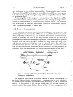
When the driver receives a message to read or write a block, it just computes where in the RAM disk memory
the requested block lies and reads from it or writes to it, instead of from or to a floppy or hard disk. Ultimately
the system task is called to carry out the transfer. This is done by phys_copy, an assembly language procedure
in the kernel that copies to or from the user program at the maximum speed of which the hardware is capable.
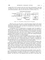
Figure 3-20. A RAM disk.
A RAM disk driver may support several areas of memory used as RAM disk, each distinguished by a different
minor device number. Usually, these areas are distinct, but in some fairly specific situations it may be
convenient to have them overlap, as we shall see in the next section.
[Page 273]
3.6.2. Overview of the RAM Disk Driver in MINIX 3
The MINIX 3 RAM disk driver is actually six closely related drivers in one. Each message to it specifies a
minor device as follows:
0: /dev/ram 2: /dev/kmem 4:
/dev/boot
1: /dev/mem 3: /dev/null 5:
/dev/zero
The first special file listed above, /dev/ram, is a true RAM disk. Neither its size nor its origin is built into the
driver. They are determined by the file system when MINIX 3 is booted. If the boot parameters specify that
the root file system is to be on the RAM disk but the RAM disk size is not specified, a RAM disk of the same
size as the root file system image device is created. A boot parameter can be used to specify a RAM disk
larger than the root file system, or if the root is not to be copied to the RAM, the specified size may be any
2
2
Simpo PDF Merge and Split Unregistered Version -
value that fits in memory and leaves enough memory for system operation. Once the size is known, a block of
memory big enough is found and removed from the memory pool by the process manager during its
initialization. This strategy makes it possible to increase or reduce the amount of RAM disk present without
having to recompile the operating system.
The next two minor devices are used to read and write physical memory and kernel memory, respectively.
When /dev/mem is opened and read, it yields the contents of physical memory locations starting at absolute
address zero (the real-mode interrupt vectors). Ordinary user programs never do this, but a system program
concerned with debugging the system might possibly need this facility. Opening /dev/mem and writing on it
will change the interrupt vectors. Needless to say, this should only be done with the greatest of caution by an
experienced user who knows exactly what he is doing.
The special file /dev/kmem is like /dev/mem, except that byte 0 of this file is byte 0 of the kernel's data
memory, a location whose absolute address varies, depending on the size of the MINIX 3 kernel text segment.
It too is used mostly for debugging and very special programs. Note that the RAM disk areas covered by these
two minor devices overlap. If you know exactly how the kernel is placed in memory, you can open /dev/mem,
seek to the beginning of the kernel's data area, and see exactly the same thing as reading from the beginning of
/dev/kmem. But, if you recompile the kernel, changing its size, or if in a subsequent version of MINIX 3 the
kernel is moved somewhere else in memory, you will have to seek a different amount in /dev/mem to see the
same thing you now see at the start of /dev/kmem. Both of these special files should be protected to prevent
everyone except the superuser from using them.
The next file in this group, /dev/null, is a special file that accepts data and throws them away. It is commonly
used in shell commands when the program being called generates output that is not needed. For example,
a.out >/dev/null
[Page 274]
runs the program a.out but discards its output. The RAM disk driver effectively treats this minor device as
having zero size, so no data are ever copied to or from it. If you read from it you will get an immediate EOF
(End of File).
If you have looked at the directory entries for these files in /dev/ you may have noticed that, of those
mentioned so far, only /dev/ram is a block special file. All the others are character devices. There is one more
block device supported by the memory driver. This is /dev/boot. From the point of view of the device driver it
is another block device implemented in RAM, just like /dev/ram. However, it is meant to be initialized by
copying a file appended to the boot image after init into memory, rather than starting with an empty block of
memory, as is done for /dev/ram. Support for this device is provided for future use and it is not used in
MINIX 3 as described in this text.
Finally, the last device supported by the memory driver is another character special file, /dev/zero. It is
sometimes convenient to have a source of zeros. Writing to /dev/zero is like writing to /dev/null; it throws
data away. But reading /dev/zero gives you zeros, in any quantity you want, whether a single character or a
disk full.
At the driver level, the code for handling /dev/ram, /dev/mem, /dev/kmem, and /dev/boot is identical. The
only difference among them is that each one corresponds to a different region of memory, indicated by the
arrays ram_origin and ram_limit, each indexed by minor device number. The file system manages devices at a
higher level. The file system interprets devices as character or block devices, and thus can mount /dev/ram
and /dev/boot and manage directories and files on these devices. For the devices defined as character devices
the file system can only read and write streams of data (although a stream read from /dev/null gets only EOF).
3
3
Simpo PDF Merge and Split Unregistered Version -
3.6.3. Implementation of the RAM Disk Driver in MINIX 3
As with other disk drivers, the main loop of the RAM disk driver is in the file driver.c. The device-specific
support for memory devices is in memory.c (line 10800). When the memory driver is compiled, a copy of the
object file called drivers/libdriver/driver.o, produced by compiling drivers/libdriver/driver.c, is linked with the
object file drivers/memory/memory.o, the product of compiling drivers/memory/memory.c.
It may be worth taking a moment to consider how the main loop is compiled. The declaration of the driver
structure in driver.h (lines 10829 to 10845) defines a data structure, but does not create one. The declaration
of m_dtab on lines 11645 to 11660 creates an instance of this with each part of the structure filled in with a
pointer to a function. Some of these functions are generic code compiled when driver.c is compiled, for
instance, all of the nop functions. Others are code compiled when memory.c is compiled, for instance,
m_do_open. Note that for the memory driver seven of the entries are do-little or do-nothing routines and the
last two are defined as NULL (which means these functions will never be called, there is no need even for a
do_nop). All this is a sure clue that the operation of a RAM disk is not terribly complicated.
[Page 275]
The memory device does not require definition of a large number of data structures, either. The array
m_geom[NR_DEVS] (line 11627) holds the base and size of each of the six memory devices in bytes, as 64
bit unsigned integers, so there is no immediate danger of MINIX 3 not being able to have a big enough RAM
disk. The next line defines an interesting structure that will not be seen in other drivers. M_seg[NR_DEVS] is
apparently just an aray of integers, but these integers are indices that allow segment descriptors to be found.
The memory device driver is unusual among user-space processes in having the ability to access regions of
memory outside of the ordinary text, data, and stack segments every process owns. This array holds the
information that allows access to the designated additional memory regions. The variable m_device just holds
the index into these arrays of the currently active minor device.
To use /dev/ram as the root device the memory driver must be initialized very early during startup of MINIX
3. The kinfo and machine structures that are defined next will hold data retrieved from the kernel during
startup that is necessary for initializing the memory driver.
One other data structure is defined before the executable code begins. This is dev_zero, an array of 1024
bytes, used to supply data when a read call is made to /dev/zero.
The main procedure main (line 11672) calls one function to do some local initialization. After that, it calls the
main loop, which gets messages, dispatches to the appropriate procedures, and sends the replies. There is no
return to main upon completion.
The next function, m_name, is trivial. It returns the string "memory" when called.
On a read or write operation, the main loop makes three calls: one to prepare a device, one to do the actual
data transfer, and one to do cleanup. For a memory device, a call to m_prepare is the first of these. It checks
that a valid minor device has been requested and then returns the address of the structure that holds the base
address and size of the requested RAM area. The second call is for m_transfer (line 11706). This does all the
work. As we saw in driver.c, all calls to read or write data are transformed into calls to read or write multiple
contiguous blocks of dataif only one block is needed the request is passed on as a request for multiple blocks
with a count of one. So only two kinds of transfer requests are passed on to the driver, DEV_GATHER,
requesting a read of one or more blocks, and DEV_SCATTER, a request to write one or more blocks. Thus,
after getting the minor device number, m_transfer enters a loop, repeated for the number of transfers
requested. Within the loop there is a switch on the device type.
The first case is for /dev/null, and the action is to return immediately on a DEV_GATHER request or on a
4
4
Simpo PDF Merge and Split Unregistered Version -
DEV_SCATTER request to fall through to the end of the switch. This is so the number of bytes transferred
(although this number is zero for /dev/null) can be returned, as would be done for any write operation.
[Page 276]
For all of the device types that refer to real locations in memory the action is similar. The requested offset is
checked against the size of the device to determine that the request is within the bounds of the memory
allocated to the device. Then a kernel call is made to copy data either to or from the memory of the caller.
There are two chunks of code that do this, however. For /dev/ram, /dev/kmem, and /dev/boot virtual addresses
are used, which requires retrieving the segment address of the memory region to be accessed from the m_seg
array, and then making a sys_vircopy kernel call (lines 11640 to 11652). For /dev/mem a physical address
is used and the call is to sys_physcopy.
The remaining operation is a read or write to /dev/zero. For reading the data is taken from the dev_zero array
mentioned earlier. You might ask, why not just generate zero values as needed, rather than copying from a
buffer full of them? Since the copying of the data to its destination has to be done by a kernel call, such a
method would require either an inefficient copying of single bytes from the memory driver to the system task,
or building code to generate zeros into the system task. The latter approach would increase the complexity of
kernel-space code, something that we would like to avoid in MINIX 3.
A memory device does not need a third step to finish a read or write operation, and the corresponding slot in
m_dtab is a call to nop_finish.
Opening a memory device is done by m_do_open (line 11801). The job is done by calling m_prepare to check
that a valid device is being referenced. More interesting than the code that exists is a comment about code that
was found here in older versions of MINIX. Previously a trick was hidden here. A call by a user process to
open /dev/mem or /dev/kmem would also magically confer upon the caller the ability to execute instructions
which access I/O ports. Pentium-class CPUs implement four privilege levels, and user processes normally run
at the least-privileged level. The CPU generates a general protection exception when an process tries to
execute an instruction not allowed at its privilege level. Providing a way to get around this was considered
safe because the memory devices could only be accessed by a user with root privileges. In any case, this
possibly risky "feature" is absent from MINIX 3 because kernel calls that allow I/O access via the system task
are now available. The comment remains, to point out that if MINIX 3 is ported to hardware that uses
memory-mapped I/O such a feature might need to be reintroduced. The function to do this, enable_iop,
remains in the kernel code to show how this can be done, although it is now an orphan.
The next function, m_init (line 11817), is called only once, when mem_task is called for the first time. This
routine uses a number of kernel calls, and is worth study to see how MINIX 3 drivers interact with kernel
space by using system task services. First a sys_getkinfo kernel call is made to get a copy of the kernel's
kinfo data. From this data it copies the base address and size of /dev/kmem into the corresponding fields of the
m_geom data structure. A different kernel call, sys_segctl, converts the physical address and size of
/dev/kmem into the segment descriptor information needed to treat the kernel memory as a virtual memory
space. If an image of a boot device has been compiled into the system boot image, the field for the base
address of /dev/boot will be non-zero. If this is so, then information to access the memory region for this
device is set up in exactly the same way it was done for /dev/kme m. Next the array used to supply data when
/dev/zero is accessed is explicitly filled with zeros. This is probably unnecessary; C compilers are supposed to
initialize newly created static variables to all zeros.
[Page 277]
Finally, m_init uses a sys_getmachine kernel call to get another set of data from the kernel, the machine
structure which flags various possible hardware alternatives. In this case the information needed is whether or
5
5
Simpo PDF Merge and Split Unregistered Version -
not the CPU is capable of protected mode operation. Based on this information the size of /dev/mem is set to
either 1 MB, or 4 GB - 1, depending upon whether MINIX 3 is running in 8088 or 80386 mode. These sizes
are the maximum sizes supported by MINIX 3 and do not have anything to do with how much RAM is
installed in the machine. Only the size of the device is set; the compiler is trusted to set the base address
correctly to zero. Also, since /dev/mem is accessed as physical (not virtual) memory there is no need to make
a sys_segctl kernel call to set up a segment descriptor.
Before we leave m_init we should mention another kernel call used here, although it is not obvious in the
code. Many of the actions taken during initialization of the memory driver are essential to proper functioning
of MINIX 3, and thus several tests are made and panic is called if a test fails. In this case panic is a library
routine which ultimately results in a sys_exit kernel call. The kernel and (as we shall see) the process
manager and the file system have their own panic routines. The library routine is provided for device drivers
and other small system components.
Surprisingly, the function we just examined, m_init, does not initialize the quintessential memory device,
/dev/ram. This is taken care of in the next function, m_ioctl (line 11863). In fact, there is only one ioctl
operation defined for the RAM disk; this is MIOCRAMSIZE, which is used by the file system to set the RAM
disk size. Much of the job is done without requiring any services from the kernel. The call to allocmem on
line 11887 is a system call, but not a kernel call. It is handled by the process manager, which maintains all of
the information necessary to find an available region of memory. However, at the end one kernel call is
needed. At line 11894 a sys_segctl call is made to convert the physical address and size returned by
allocmem into the segment information needed for further access.
The last function defined in memory.c is m_geometry. This is a fake. Obviously, cylinders, heads, and sectors
are irrelevant in addressing semiconductor memory, but if a request is made for such information for a
memory device this function pretends it has 64 heads and 32 sectors per track, and calculates from the size
how many cylinders there are.
6
6
Simpo PDF Merge and Split Unregistered Version -
[Page 278]
3.7. Disks
All modern computers except embedded ones have disk drives. For that reason, we will now study them,
starting with the hardware, then moving on to say some general things about disk software. After that we will
delve into the way MINIX 3 controls its disks.
3.7.1. Disk Hardware
All real disks are organized into cylinders, each one containing as many tracks as there are heads stacked
vertically. The tracks are divided into sectors, with the number of sectors around the circumference typically
being 8 to 32 on floppy disks, and up to several hundred on some hard disks. The simplest designs have the
same number of sectors on each track. All sectors contain the same number of bytes, although a little thought
will make it clear that sectors close to the outer rim of the disk will be physically longer than those close to
the hub. The time to read or write each sector will be same, however. The data density is obviously higher on
the innermost cylinders, and some disk designs require a change in the drive current to the read-write heads
for the inner tracks. This is handled by the disk controller hardware and is not visible to the user (or the
implementer of an operating system).
The difference in data density between inner and outer tracks means a sacrifice in capacity, and more
sophisticated systems exist. Floppy disk designs that rotate at higher speeds when the heads are over the outer
tracks have been tried. This allows more sectors on those tracks, increasing disk capacity. Such disks are not
supported by any system for which MINIX 3 is currently available, however. Modern large hard drives also
have more sectors per track on outer tracks than on inner tracks. These are IDE (Integrated Drive Electronics)
drives, and the sophisticated processing done by the drive's built-in electronics masks the details. To the
operating system they appear to have a simple geometry with the same number of sectors on each track.
The drive and controller electronics are as important as the mechanical hardware. The main element of the
disk controller is a specialized integrated circuit, really a small microcomputer. Once this would have been on
a card plugged into the computer's backplane, but on modern systems, the disk controller is on the
parentboard. For a modern hard disk this disk controller circuitry may be simpler than for a floppy disk, since
a hard drive has a powerful electronic controller integrated into the drive itself.
A device feature that has important implications for the disk driver is the possibility of a controller doing
seeks on two or more drives at the same time. These are known as overlapped seeks. While the controller and
software are waiting for a seek to complete on one drive, the controller can initiate a seek on another drive.
Many controllers can also read or write on one drive while seeking on one or more other drives, but a floppy
disk controller cannot read or write on two drives at the same time. (Reading or writing requires the controller
to move bits on a microsecond time scale, so one transfer uses up most of its computing power.) The situation
is different for hard disks with integrated controllers, and in a system with more than one of these hard drives
they can operate simultaneously, at least to the extent of transferring between the disk and the controller's
buffer memory. Only one transfer between the controller and the system memory is possible at once, however.
The ability to perform two or more operations at the same time can reduce the average access time
considerably.
[Page 279]
One thing to be aware of in looking at the specifications of modern hard disks is that the geometry specified,
and used by the driver software, is almost always different from the physical format. In fact, if you look up the
1
1
Simpo PDF Merge and Split Unregistered Version -
"recommended setup parameters" for a large hard disk, you are likely to find it specified as 16383 cylinders,
16 heads, and 63 sectors per track, no matter what the size of the disk. These numbers correspond to a disk
size of 8 GB, but are used for all disks this size or larger. The designers of the original IBM PC ROM BIOS
allotted a 6-bit field for the sector count, 4 bits to specify the head, and 14 bits to select a cylinder. With 512
byte sectors this comes out to 8 GB. So if you try to install a large hard drive into a very old computer you
may find you can access only 8 GB, even though you have a much bigger disk. The usual way around this
limitation is to use logical block addressing in which disk sectors are just numbered consecutively starting at
zero, without regard to the disk geometry.
The geometry of a modern disk is a fiction, anyway. On a modern disk the surface is divided into 20 or more
zones. Zones closer to the center of the disk have fewer sectors per track than zones nearer the periphery.
Thus sectors have approximately the same physical length no matter where they are located on the disk,
making more efficient use of the disk surface. Internally, the integrated controller addresses the disk by
calculating the zone, cylinder, head, and sector. But this is never visible to the user, and the details are rarely
found in published specifications. The bottom line is, there is no point to using cylinder, head, sector
addressing of a disk unless you are working with a very old computer that does not support logical block
addressing. Also, it does not make sense to buy a new 400 GB drive for the PC-XT you bought in 1983; you
will get no more than 8 GB use out of it.
This is a good place to mention a confusing point about disk capacity specifications. Computer professionals
are accustomed to using powers of 2a Kilobyte (KB) is 2
10
= 1024 bytes, a Megabyte (MB) is 2
20
= 1024
2
bytes, etc., to express the size of memory devices. A Gigabyte (GB), then, should be 1024
3
, or 2
30
bytes.
However, disk manufacturers have adopted the habit of using the term "Gigabyte" to mean 10
9
, which (on
paper) instantly increases the size of their products. Thus the 8 GB limit mentioned above is an 8.4 GB disk in
the language of the disk salesman. Recently there has been a move toward using the term Gibibyte (GiB) to
mean 2
30
. However, in this text the authors, being set in their ways and in protest of the hijacking of tradition
for advertising purposes, will continue to use terms like Megabyte and Gigabyte to mean what they have
always meant.
[Page 280]
3.7.2. RAID
Although modern disks are much faster than older ones, improvements in CPU performance have far
exceeded improvements in disk performance. It has occurred to various people over the years that parallel
disk I/O might be helpful. Thus has come about a new class of I/O device called a RAID, an acronym for
Redundant Array of Independent Disks. Actually, the designers of RAID (at Berkeley) originally used the
acronym RAID to stand for "Redundant Array of Inexpensive Disks" to contrast this design with a SLED
(Single Large Expensive Disk). However, when RAID became commercially popular, disk manufacturers
changed the meaning of the acronym because it was tough to sell an expensive product whose name stood for
"inexpensive." The basic idea behind a RAID is to install a box full of disks next to the computer, typically a
large server, replace the disk controller card with a RAID controller, copy the data over to the RAID, and then
continue normal operation.
The independent disks can be used together in a variety of ways. We do not have space for an exhaustive
description of all of these, and MINIX 3 does not (yet) support RAID, but an introduction to operating
systems should at least mention some of the possibilities. RAID can be used both to speed disk access and to
make data more secure.
For example, consider a very simple RAID of two drives. When multiple sectors of data are to be written to
the "disk" the RAID controller sends sectors 0, 2, 4, etc., to the first drive, and sectors 1, 3, 5, etc., to the
second drive. The controller divides up the data and the two disks are written simultaneously, doubling the
2
2
Simpo PDF Merge and Split Unregistered Version -
writing speed. When reading, both drives are read simultaneously, but the controller reassembles the data in
the proper order, and to the rest of the system it just looks like the reading speed is twice as fast. This
technique is called striping. This is a simple example of RAID level 0. In practice four or more drives would
be used. This works best when data are usually read or written in large blocks. Obviously, nothing is gained if
a typical disk request is for a single sector at a time.
The previous example shows how multiple drives can increase speed. What about reliability? RAID level 1
works like RAID level 0, except the data is duplicated. Again, a very simple array of two drives could be
used, and all of the data could be written to both of them. This provides no speedup, but there is 100%
redundancy. If an error is detected during reading there is no need for a retry if the other drive reads the data
correctly. The controller just has to make sure the correct data is passed on to the system. It probably would
not be a good idea to skip retries if errors are detected while writing, however. And if errors occur frequently
enough that skipping retries actually makes reading noticeably faster it is probably time to decide complete
failure is imminent. Typically the drives used for RAIDs are hot-swappable, meaning they can be replaced
without powering down the system.
[Page 281]
More complex arrays of multiple disks can increase both speed and reliability. Consider, for instance, an array
of 7 disks. Bytes could be split into 4-bit nybbles, with each bit being recorded on one of four drives and with
the other three drives being used to record a three bit error-correcting code. If a drive goes bad and needs to be
hot-swapped for a new one, a missing drive is equivalent to one bad bit, so the system can keep running while
maintenance is done. For the cost of seven drives you get reliable performance that is four times as fast as one
drive, and no downtime.
3.7.3. Disk Software
In this section we will look at some issues related to disk drivers in general. First, consider how long it takes
to read or write a disk block. The time required is determined by three factors:
1. The seek time (the time to move the arm to the proper cylinder).
2. The rotational delay (the time for the proper sector to rotate under the head).
3. The actual data transfer time.
For most disks, the seek time dominates the other two times, so reducing the mean seek time can improve
system performance substantially.
Disk devices are prone to errors. Some kind of error check, a checksum or a cyclic redundancy check, is
always recorded along with the data in each sector on a disk. Even the sector addresses recorded when the
disk is formatted have check data. Floppy disk controller hardware can usually report when an error is
detected, but the software must then decide what to do about it. Hard disk controllers often take on much of
this burden.
Particularly with hard disks, the transfer time for consecutive sectors within a track can be very fast. Thus
reading more data than requested and caching it in memory can be very effective in speeding disk access.
3
3
Simpo PDF Merge and Split Unregistered Version -
Disk Arm Scheduling Algorithms
If the disk driver accepts requests one at a time and carries them out in that order, that is, First-Come,
First-Served (FCFS), little can be done to optimize seek time. However, another strategy is possible when the
disk is heavily loaded. It is likely that while the arm is seeking on behalf of one request, other disk requests
may be generated by other processes. Many disk drivers maintain a table, indexed by cylinder number, with
all pending requests for each cylinder chained together in a linked list headed by the table entries.
[Page 282]
Given this kind of data structure, we can improve upon the first-come, first-served scheduling algorithm. To
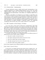
see how, consider a disk with 40 cylinders.A request comes in to read a block on cylinder 11. While the seek
to cylinder 11 is in progress, new requests come in for cylinders 1, 36, 16, 34, 9, and 12, in that order. They
are entered into the table of pending requests, with a separate linked list for each cylinder. The requests are
shown in Fig. 3-21.
Figure 3-21. Shortest Seek First (SSF) disk scheduling algorithm.
[View full size image]
When the current request (for cylinder 11) is finished, the disk driver has a choice of which request to handle
next. Using FCFS, it would go next to cylinder 1, then to 36, and so on. This algorithm would require arm
motions of 10, 35, 20, 18, 25, and 3, respectively, for a total of 111 cylinders.
Alternatively, it could always handle the closest request next, to minimize seek time. Given the requests of
Fig. 3-21, the sequence is 12, 9, 16, 1, 34, and 36, as shown as the jagged line at the bottom of Fig. 3-21. With
this sequence, the arm motions are 1, 3, 7, 15, 33, and 2, for a total of 61 cylinders. This algorithm, Shortest
Seek First (SSF), cuts the total arm motion almost in half compared to FCFS.
Unfortunately, SSF has a problem. Suppose that more requests keep coming in while the requests of Fig. 3-21
are being processed. For example, if, after going to cylinder 16, a new request for cylinder 8 is present, that
request will have priority over cylinder 1. If a request for cylinder 13 then comes in, the arm will next go to
13, instead of 1. With a heavily loaded disk, the arm will tend to stay in the middle of the disk most of the
time, so requests at either extreme will have to wait until a statistical fluctuation in the load causes there to be
no requests near the middle. Requests far from the middle may get poor service. The goals of minimal
response time and fairness are in conflict here.
Tall buildings also have to deal with this trade-off. The problem of scheduling an elevator in a tall building is
similar to that of scheduling a disk arm. Requests come in continuously calling the elevator to floors
(cylinders) at random. The microprocessor running the elevator could easily keep track of the sequence in
which customers pushed the call button and service them using FCFS. It could also use SSF.
4
4
Simpo PDF Merge and Split Unregistered Version -
[Page 283]
However, most elevators use a different algorithm to reconcile the conflicting goals of efficiency and fairness.
They keep moving in the same direction until there are no more outstanding requests in that direction, then
they switch directions. This algorithm, known both in the disk world and the elevator world as the elevator
algorithm, requires the software to maintain 1 bit: the current direction bit, UP or DOWN. When a request
finishes, the disk or elevator driver checks the bit. If it is UP, the arm or cabin is moved to the next highest
pending request. If no requests are pending at higher positions, the direction bit is reversed. When the bit is set
to DOWN, the move is to the next lowest requested position, if any.
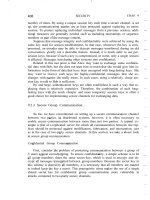
Figure 3-22 shows the elevator algorithm using the same seven requests as Fig. 3-21, assuming the direction
bit was initially UP. The order in which the cylinders are serviced is 12, 16, 34, 36, 9, and 1, which yields arm
motions of 1, 4, 18, 2, 27, and 8, for a total of 60 cylinders. In this case the elevator algorithm is slightly better
than SSF, although it is usually worse. One nice property that the elevator algorithm has is that given any
collection of requests, the upper bound on the total motion is fixed: it is just twice the number of cylinders.
Figure 3-22. The elevator algorithm for scheduling disk requests.
[View full size image]
A slight modification of this algorithm that has a smaller variance in response times is to always scan in the
same direction (Teory, 1972). When the highest numbered cylinder with a pending request has been serviced,
the arm goes to the lowest-numbered cylinder with a pending request and then continues moving in an upward
direction. In effect, the lowest-numbered cylinder is thought of as being just above the highest-numbered
cylinder.
Some disk controllers provide a way for the software to inspect the current sector number under the head.
With such a controller, another optimization is possible. If two or more requests for the same cylinder are
pending, the driver can issue a request for the sector that will pass under the head next. Note that when
multiple tracks are present in a cylinder, consecutive requests can be for different tracks with no penalty. The
controller can select any of its heads instantaneously, because head selection involves neither arm motion nor
rotational delay.
[Page 284]
With a modern hard disk, the data transfer rate is so much faster than that of a floppy disk that some kind of
automatic caching is necessary. Typically any request to read a sector will cause that sector and up to the rest
of the current track to be read, depending upon how much space is available in the controller's cache memory.
Current caches are often 8 MB or more.
5
5
Simpo PDF Merge and Split Unregistered Version -
When several drives are present, a pending request table should be kept for each drive separately. Whenever
any drive is idle, a seek should be issued to move its arm to the cylinder where it will be needed next
(assuming the controller allows overlapped seeks). When the current transfer finishes, a check can be made to
see if any drives are positioned on the correct cylinder. If one or more are, the next transfer can be started on a
drive that is already on the right cylinder. If none of the arms is in the right place, the driver should issue a
new seek on the drive that just completed a transfer and wait until the next interrupt to see which arm gets to
its destination first.
Error Handling
RAM disks do not have to worry about seek or rotational optimization: at any instant all blocks can be read or
written without any physical motion. Another area in which RAM disks are simpler than real disks is error
handling. RAM disks always work; real ones do not always work. They are subject to a wide variety of errors.
Some of the more common ones are:
1. Programming error (e.g., request for nonexistent sector).
2. Transient checksum error (e.g., caused by dust on the head).
3. Permanent checksum error (e.g., disk block physically damaged).
4. Seek error (e.g., the arm was sent to cylinder 6 but it went to 7).
5. Controller error (e.g., controller refuses to accept commands).
It is up to the disk driver to handle each of these as best it can.
Programming errors occur when the driver tells the controller to seek to a nonexistent cylinder, read from a
nonexistent sector, use a nonexistent head, or transfer to or from nonexistent memory. Most controllers check
the parameters given to them and complain if they are invalid. In theory, these errors should never occur, but
what should the driver do if the controller indicates that one has happened? For a home-grown system, the
best thing to do is stop and print a message like "Call the programmer" so the error can be tracked down and
fixed. For a commercial software product in use at thousands of sites around the world, this approach is less
attractive. Probably the only thing to do is terminate the current disk request with an error and hope it will not
recur too often.
[Page 285]
Transient checksum errors are caused by specks of dust in the air that get between the head and the disk
surface. Most of the time they can be eliminated by just repeating the operation a few times. If the error
persists, the block has to be marked as a bad block and avoided.
One way to avoid bad blocks is to write a very special program that takes a list of bad blocks as input and
carefully hand crafts a file containing all the bad blocks. Once this file has been made, the disk allocator will
think these blocks are occupied and never allocate them. As long as no one ever tries to read the bad block
file, no problems will occur.
Not reading the bad block file is easier said than done. Many disks are backed up by copying their contents a
track at a time to a backup tape or disk drive. If this procedure is followed, the bad blocks will cause trouble.
Backing up the disk one file at a time is slower but will solve the problem, provided that the backup program
6
6
Simpo PDF Merge and Split Unregistered Version -
knows the name of the bad block file and refrains from copying it.
Another problem that cannot be solved with a bad block file is the problem of a bad block in a file system data
structure that must be in a fixed location. Almost every file system has at least one data structure whose
location is fixed, so it can be found easily. On a partitioned file system it may be possible to repartition and
work around a bad track, but a permanent error in the first few sectors of either a floppy or hard disk generally
means the disk is unusable.
"Intelligent" controllers reserve a few tracks not normally available to user programs. When a disk drive is
formatted, the controller determines which blocks are bad and automatically substitutes one of the spare tracks
for the bad one. The table that maps bad tracks to spare tracks is kept in the controller's internal memory and
on the disk. This substitution is transparent (invisible) to the driver, except that its carefully worked out
elevator algorithm may perform poorly if the controller is secretly using cylinder 800 whenever cylinder 3 is
requested. The technology of manufacturing disk recording surfaces is better than it used to be, but it is still
not perfect. However, the technology of hiding the imperfections from the user has also improved. Many
controllers also manage new errors that may develop with use, permanently assigning substitute blocks when
they determine that an error is unrecoverable. With such disks the driver software rarely sees any indication
that there any bad blocks.
Seek errors are caused by mechanical problems in the arm. The controller keeps track of the arm position
internally. To perform a seek, it issues a series of pulses to the arm motor, one pulse per cylinder, to move the
arm to the new cylinder. When the arm gets to its destination, the controller reads the actual cylinder number
(written when the drive was formatted). If the arm is in the wrong place, a seek error has occurred and some
corrective action is required.
[Page 286]
Most hard disk controllers correct seek errors automatically, but many floppy controllers (including the IBM
PCs) just set an error bit and leave the rest to the driver. The driver handles this error by issuing a
recalibrate command, to move the arm as far out as it will go and reset the controller's internal idea of
the current cylinder to 0. Usually, this solves the problem. If it does not, the drive must be repaired.
As we have seen, the controller is really a specialized little computer, complete with software, variables,
buffers, and occasionally, bugs. Sometimes an unusual sequence of events such as an interrupt on one drive
occurring simultaneously with a recalibrate command for another drive will trigger a bug and cause the
controller to go into a loop or lose track of what it was doing. Controller designers usually plan for the worst
and provide a pin on the chip which, when asserted, forces the controller to forget whatever it was doing and
reset itself. If all else fails, the disk driver can set a bit to invoke this signal and reset the controller. If that
does not help, all the driver can do is print a message and give up.
Track-at-a-Time Caching
The time required to seek to a new cylinder is usually much more than the rotational delay, and always vastly
more than the transfer time to read or write one sector. In other words, once the driver has gone to the trouble
of moving the arm somewhere, it hardly matters whether it reads one sector or a whole track. This effect is
especially true if the controller provides rotational sensing, so the driver can see which sector is currently
under the head and issue a request for the next sector, thereby making it possible to read an entire disk track in
a single rotation time. (Normally it takes half a rotation plus one sector time just to read a single sector, on the
average.)
Some disk drivers take advantage of these timing properties by maintaining a secret track-at-a-time cache,
unknown to the device-independent software. If a sector that is in the cache is needed, no disk transfer is
required. A disadvantage of track-at-a-time caching (in addition to the software complexity and buffer space
7
7
Simpo PDF Merge and Split Unregistered Version -
needed) is that transfers from the cache to the calling program will have to be done by the CPU using a
programmed loop, rather than letting the DMA hardware do the job.
Some controllers take this process a step further, and do track-at-a-time caching in their own internal memory,
transparent to the driver, so that transfer between the controller and memory can use DMA. If the controller
works this way, there is little point in having the disk driver do it as well. Note that both the controller and the
driver are in a good position to read and write entire tracks in one command, but that the device-independent
software cannot, because it regards a disk as a linear sequence of blocks, without regard to how they are
divided up into tracks and cylinders. Only the controller knows the true geometry for sure.
[Page 287]
3.7.4. Overview of the Hard Disk Driver in MINIX 3
The hard disk driver is the first part of MINIX 3 we have looked at that has to deal with a range of different
types of hardware. Before we discuss the driver, we will briefly consider some of the problems hardware
differences can cause.
The "PC" is really a family of different computers. Not only are different processors used in different
members of the family, there are also some major differences in the basic hardware. MINIX 3 has been
developed on and for newer systems with Pentium-class CPUs, but even among these there are differences.
For instance, the oldest Pentium systems use the 16-bit AT bus originally designed for the 80286 processor. A
feature of the AT bus is that it was cleverly designed so older 8-bit peripherals could still be used. Later
systems added a 32-bit PCI bus for peripherals, while still providing AT bus slots. The newest designs have
dropped AT-bus support, providing only a PCI bus. But it is reasonable to expect that users with computers of
a certain age may want to be able to use MINIX 3 with a mix of 8-bit, 16-bit, and 32-bit peripherals.
For every bus there is a different family of I/O adapters. On older systems these are separate circuit boards
which plug into the system parentboard. On newer systems many standard adapters, especially disk
controllers, are integrated parts of the parentboard chipset. In itself this is not a problem for the programmer,
as integrated adapters usually have a software interface identical to that of removable devices. Also, integrated
controllers can usually be disabled. This allows use of a more advanced add-on device, such as a SCSI
controller, in place of a built-in device. To take advantage of this flexibility the operating system should not
be restricted to using just one kind of adapter.
In the IBM PC family, as in most other computer systems, each bus design also comes with firmware in the
Basic I/O System Read-Only Memory (the BIOS ROM) which is designed to bridge the gap between the
operating system and the peculiarities of the hardware. Some peripheral devices may even provide extensions
to the BIOS in ROM chips on the peripheral cards themselves. The difficulty faced by an operating system
implementer is that the BIOS in IBM-type computers (certainly the early ones) was designed for an operating
system, MSDOS, that does not support multiprogramming and that runs in 16-bit real mode, the lowest
common denominator of the various modes of operation available from the 80x86 family of CPUs.
The implementer of a new operating system for the IBM PC is thus faced with several choices. One is whether
to use the driver support for peripherals in the BIOS or to write new drivers from scratch. This was not a hard
choice in the design of early versions of MINIX, since the BIOS was in many ways not suitable to its needs.
Of course, to start MINIX 3 the boot monitor uses the BIOS to do the initial loading of the system, whether
from hard disk, CD-ROM, or floppy disk there is no practical alternative to doing it this way. Once we have
loaded the system, including our own I/O drivers, we can do better than the BIOS.
[Page 288]
8
8
Simpo PDF Merge and Split Unregistered Version -
The second choice then must be faced: without the BIOS support how are we going to make our drivers adapt
to the varied kinds of hardware on different systems? To make the discussion concrete, consider that there are
two fundamentally different types of hard disk controller usable on the modern 32-bit Pentium systems for
which MINIX 3 has been designed: the integrated IDE controller and add-on SCSI controllers for the PCI bus.
If you would like to take advantage of older hardware and adapt MINIX 3 to work on the hardware targeted
by earlier versions of MINIX, there are four hard disk controller types to consider: the original 8-bit XT-type
controller, the 16-bit AT-type controller, and two different controllers for two different types of IBM PS/2
series computers. There are several possible ways to deal with all these alternatives:
1. Recompile a unique version of the operating system for each type of hard disk controller we need to
accommodate.
2. Compile several different hard disk drivers into the boot image and have the system automatically
determine at startup time which one to use.
3. Compile several different hard disk drivers into the boot image and provide a way for the user to
determine which one to use.
As we shall see, these are not mutually exclusive.
The first way is really the best way in the long run. For use on a particular installation there is no need to use
up disk and memory space with code for alternative drivers that will never be used. However, it is a nightmare
for the distributor of the software. Supplying four different startup disks and advising users on how to use
them is expensive and difficult. Thus, another method is advisable, at least for the initial installation.
The second method is to have the operating system probe the peripherals, by reading the ROM on each card or
writing and reading I/O ports to identify each card. This is possible (and works better on newer IBM-type
systems than on older ones), but it does not accommodate nonstandard I/O devices. Also, probing I/O ports to
identify one device sometimes can activate another device which seizes control and disables the system. This
method complicates the startup code for each device, and yet still does not work very well. Operating systems
that do use this method generally have to provide some kind of override, typically a mechanism such as we
use with MINIX 3.
The third method, used in MINIX 3, is to allow inclusion of several drivers in the boot image. The MINIX 3
boot monitor allows various boot parameters to be read at startup time. These can be entered by hand, or
stored permanently on the disk. At startup time, if a boot parameter of the form
label = AT
is found, this forces the IDE disk controller (at_wini) to be used when MINIX 3 is started. This depends upon
the at_wini driver being assigned this label. Labels are assigned when the boot image is compiled.
[Page 289]
There are two other things MINIX 3 does to try to minimize problems with multiple hard disk drivers. One is
that there is, after all, a driver that interfaces between MINIX 3 and the ROM BIOS hard disk support. This
driver is almost guaranteed to work on any system and can be selected by use of a
label=BIOS
9
9
Simpo PDF Merge and Split Unregistered Version -
boot parameter. Generally, this should be a last resort, however. MINIX 3 as described here runs only in
protected mode on systems with an 80386 or better processor, but the BIOS code always runs in real (8086)
mode. Switching out of protected mode and back again whenever a routine in the BIOS is called is very slow.
The other strategy MINIX 3 uses in dealing with drivers is to postpone initialization until the last possible
moment. Thus, if on some hardware configuration none of the hard disk drivers work, we can still start
MINIX 3 from a floppy disk and do some useful work. MINIX 3 will have no problems as long as no attempt
is made to access the hard disk. This may not seem like a major breakthrough in user friendliness, but
consider this: if all the drivers try to initialize immediately on system startup, the system can be totally
paralyzed by improper configuration of some device we do not need anyway. By postponing initialization of
each driver until it is needed, the system can continue with whatever does work, while the user tries to resolve
the problems.
We learned this lesson the hard way: earlier versions of MINIX tried to initialize the hard disk as soon as the
system was booted. If no hard disk was present, the system hung. This behavior was especially unfortunate
because MINIX would run quite happily on a system without a hard disk, albeit with restricted storage
capacity and reduced performance.
In the discussion in this section and the next, we will take as our model the AT-style hard disk driver, which is
the default driver in the standard MINIX 3 distribution. This is a versatile driver that handles hard disk
controllers from the ones used in the earliest 80286 systems to modern EIDE (Extended Integrated Drive
Electronics) controllers that handle gigabyte capacity hard disks. Modern EIDE controllers also support
standard CD-ROM drives. However, in order to simplify our discussion the extensions that support
CD-ROMs have been taken out of the code listed in Appendix B. The general aspects of hard disk operation
we discuss in this section apply to the other supported drivers as well.
The main loop of the hard disk driver is the same common code we have already discussed, and supports the
standard nine kinds of requests that can be made. A DEV_OPEN request can entail a substantial amount of
work, as there are always partitions and may be subpartitions on a hard disk. These must be read when a
device is opened, (i.e., when it is first accessed). When CD-ROMs are supported, on a DEV_OPEN the
presence of the medium must be verified, since it is removable. On a CD-ROM a DEV_CLOSE operation
also has meaning: it requires that the door be unlocked and the CD-ROM ejected. There are other
complications of removable media that are more applicable to floppy drives, so we will discuss these in a later
section. For CD-ROMs a DEV_IOCTL operation is used to set a flag to mark that the medium should be
ejected from the drive upon a DEV_CLOSE. A DEV_IOCTL operation is also used to read and write partition
tables.
[Page 290]
DEV_READ, DEV_WRITE, DEV_GATHER and DEV_SCATTER requests are each handled in two phases,
prepare and transfer, as we saw previously. For the hard disk DEV_CANCEL and DEV_SELECT calls are
ignored.
No scheduling is done by the hard disk device driver at all, that is done by the file system, which assembles
the vector requests for gather/scatter I/O. Requests come from the file system cache as DEV_GATHER or
DEV_SCATTER requests for multiples of blocks (4-KB in the default configuration of MINIX 3), but the
hard disk driver is able to handle requests for any multiple of a sector (512 bytes). In any case, as we have
seen, the main loop of all disk drivers transforms requests for single blocks of data into one element vector
requests.
Requests for reading and writing are not mixed in a vector of requests, nor can requests be marked as optional.
10
10
Simpo PDF Merge and Split Unregistered Version -
The elements of a request vector are for contiguous disk sectors, and the vector is sorted by the file system
before being passed to the device driver, so it suffices to specify just the starting position on the disk for an
entire array of requests.
The driver is expected to succeed in reading or writing at least the first request in a request vector, and to
return when a request fails. It is up to the file system to decide what to do; the file system will try to complete
a write operation but will return to the calling process only as much data as it can get on a read.
The file system itself, by using scattered I/O, can implement something similar to Teory's version of the
elevator algorithmrecall that in a scattered I/O request the list of requests is sorted on the block number. The
second step in scheduling takes place in the controller of a modern hard disk. Such controllers are "smart" and
can buffer large quantities of data, using internally programmed algorithms to retrieve data in the most
efficient order, irrespective of the order of receipt of the requests.
3.7.5. Implementation of the Hard Disk Driver in MINIX 3
Small hard disks used on microcomputers are sometimes called "winchester" disks. The term was IBM's code
name for the project that developed the disk technology in which the read/write heads fly on a thin cushion of
air and land on the recording medium when the disk stops spinning. The explanation of the name is that an
early model had two data modules, a 30-Mbyte fixed and a 30-Mbyte removable one. Supposedly this
reminded the developers of the Winchester 30-30 firearm which figures in many tales of the United States'
western frontier. Whatever the origin of the name, the basic technology remains the same, although today's
typical PC disk is much smaller and the capacity is much larger than the 14-inch disks that were typical of the
early 1970s when the winchester technology was developed.
[Page 291]
The MINIX 3 AT-style hard disk driver is in at_wini.c (line 12100). This is a complicated driver for a
sophisticated device, and there are several pages of macro definitions specifying controller registers, status
bits and commands, data structures, and prototypes. As with other block device drivers, a driver structure,
w_dtab (lines 12316 to 12331), is initialized with pointers to the functions that actually do the work. Most of
them are defined in at_wini.c, but as the hard disk requires no special cleanup operation, its dr_cleanup entry
points to the common nop_cleanup in driver.c, shared with other drivers that have no special cleanup
requirement. Several other possible functions are also irrelevant for this driver and also are initialized to point
to nop_functions. The entry function, called at_winchester_task (line 12336), calls a procedure that does
hardware-specific initialization and then calls the main loop in driver.c, passing the address of w_dtab. The
main loop, driver_task in libdriver/driver.c, runs forever, dispatching calls to the various functions pointed to
by the driver table.
Since we are now dealing with real electromechanical storage devices, there is a substantial amount of work to
be done by init_params (line 12347) to initialize the hard disk driver. Various parameters about the hard disks
are kept in the wini table defined on lines 12254 to 12276, which has an element for each of the
MAX_DRIVES (8) drives supported, up to four conventional IDE drives, and up to four drives on the PCI
bus, either plug-in IDE controllers or SATA (Serial AT Attachment) controllers.
Following the policy of postponing initialization steps that could fail until the first time they are truly
necessary, init_params does not do anything that requires accessing the disk devices themselves. The main
thing it does is to copy information about the hard disk logical configuration into the wini array. The ROM
BIOS on a Pentium-class computer retrieves basic configuration information from the CMOS memory used to
preserve basic configuration data. The BIOS does this when the computer is first turned on, before the first
part of the MINIX 3 loading process begins. On lines 12366 to 12392 the information is copied from the
BIOS. Many of the constants used here, such as NR_HD_DRIVES_ADDR are defined in include/ibm/bios.h,
11
11
Simpo PDF Merge and Split Unregistered Version -
a file which is not listed in Appendix B but which can be found on the MINIX 3 CD-ROM. It is not
necessarily fatal if this information cannot be retrieved. If the disk is a modern one, the information can be
retrieved directly from the disk when it is accessed for the first time. Following the entry of data obtained
from the BIOS, additional disk information is filled in for each drive using a call to the next function,
init_drive.
On older systems with IDE controllers, the disk functions as if it were an ATstyle peripheral card, even
though it may be integrated on the parentboard. Modern drive controllers usually function as PCI devices,
with a 32-bit data path to the CPU, rather than the 16-bit AT bus. Fortunately for us, once initialization is
complete, the interface to both generations of disk controller appears the same to the programmer. To make
this work, init_params_pci (line 12437) is called if necessary to get the parameters of the PCI devices. We
will not describe the details of this routine, but a few points should be mentioned. First, the boot parameter
ata_instance is used on line 12361 to set the value of the variable w_instance. If the boot parameter is not
explicitly set the value will be zero. If it is set and greater than zero the test on line 12365 causes querying the
BIOS and initialization of standard IDE drives to be skipped. In this case only drives found on the PCI bus
will be registered.
[Page 292]
The second point is that a controller found on the PCI bus will be identified as controlling devices c0d4
through c0d7. If w_instance is non-zero the drive identifiers c0d0 through c0d3 will be skipped, unless a PCI
bus controller identifies itself as "compatible." Drives handled by a compatible PCI bus controller will be
designated c0d0 through c0d3. For most MINIX 3 users all of these complications can probably be ignored. A
computer with less than four drives (including the CD-ROM drive), will most likely appear to the user to have
the classical configuration, with drives designated c0d0 to c0d3, whether they are connected to IDE or PCI
controllers, and whether or not they use the classic 40-pin parallel connectors or the newer serial connectors.
But the programming required to create this illusion is complicated.
After the call to the common main loop, nothing may happen for a while until the first attempt is made to
access the hard disk. When the first attempt to access a disk is made a message requesting a DEV_OPEN
operation will be received by the main loop and w_do_open (line 12521) will be indirectly called. In turn,
w_do_open calls w_prepare to determine if the device requested is valid, and then w_identify to identify the
type of device and initialize some more parameters in the wini array. Finally, a counter in the wini array is
used to test whether this is first time the device has been opened since MINIX 3 was started. After being
examined, the counter is incremented. If it is the first DEV_OPEN operation, the partition function (in
drvlib.c) is called.
The next function, w_prepare (line 12577), accepts an integer argument, device, which is the minor device
number of the drive or partition to be used, and returns a pointer to the device structure that indicates the base
address and size of the device. In the C language, the use of an identifier to name a structure does not preclude
use of the same identifier to name a variable. Whether a device is a drive, a partition, or a subpartition can be
determined from the minor device number. Once w_prepare has completed its job, none of the other functions
used to read or write the disk need to concern themselves with partitioning. As we have seen, w_prepare is
called when a DEV_OPEN request is made; it is also one phase of the prepare/transfer cycle used by all data
transfer requests.
Software-compatible AT-style disks have been in use for quite a while, and w_identify (line 12603) has to
distinguish between a number of different designs that have been introduced over the years. The first step is to
see that a readable and writeable I/O port exists where one should exist on all disk controllers in this family.
This is the first example we have seen of I/O port access by a user-space driver, and the operation merits a
description. For a disk device I/O is done using a command structure, defined on lines 12201 to 12208, which
is filled in with a series of byte values. We will describe this in a bit more detail later; for the moment note
that two bytes of this structure are filled in, one with a value ATA_IDENTIFY, interpreted as a command that
12
12
Simpo PDF Merge and Split Unregistered Version -
asks an ATA (AT Attached) drive to identify itself, and another with a bit pattern that selects the drive. Then
com_simple is called.
[Page 293]
This function hides all the work of constructing a vector of seven I/O port addresses and bytes to be written to
them, sending this information to the system task, waiting for an interrupt, and checking the status returned.
This tests that the drive is alive and allows a string of 16-bit values to be read by the sys_insw kernel call
on line 12629. Decoding this information is a messy process, and we will not describe it in detail. Suffice it to
say that a considerable amount of information is retrieved, including a string that identifies the model of the
disk, and the preferred physical cylinder, head, and sector parameters for the device. (Note that the "physical"
configuration reported may not be the true physical configuration, but we have no alternative to accepting
what the disk drive claims.) The disk information also indicates whether or not the disk is capable of Logical
Block Addressing (LBA). If it is, the driver can ignore the cylinder, head, and sector parameters and can
address the disk using absolute sector numbers, which is much simpler.
As we mentioned earlier, it is possible that init_params may not recover the logical disk configuration
information from the BIOS tables. If that happens, the code at lines 12666 to 12674 tries to create an
appropriate set of parameters based on what it reads from the drive itself. The idea is that the maximum
cylinder, head, and sector numbers can be 1023, 255, and 63 respectively, due to the number of bits allowed
for these fields in the original BIOS data structures.
If the ATA_IDENTIFY command fails, it may simply mean that the disk is an older model that does not
support the command. In this case the logical configuration values previously read by init_params are all we
have. If they are valid, they are copied to the physical parameter fields of wini; otherwise an error is returned
and the disk is not usable.
Finally, MINIX 3 uses a u32_t variable to count addresses in bytes. This limits the size of a partition to 4 GB.
However, the device structure used to record the base and size of a partition (defined in
drivers/libdriver/driver.h on lines 10856 to 10858) uses u64_t numbers, and a 64 bit multiplication operation
is used to calculate the size of the drive on (line 12688), and the base and size of the whole drive are then
entered into the wini array, and w_specify is called, twice if necessary, to pass the parameters to be used back
to the disk controller (line 12691). Finally, more kernel calls are made:a sys_irqsetpolicy call (line
12699) ensures that when a disk controller interrupt occurs and is serviced the interrupt will be automatically
reenabled in preparation for the next one. Following that, a sys_irqenable call actually enables the
interrupt.
[Page 294]
W_name (line 12711) returns a pointer to a string containing the device name, which will be either "AT-D0,"
"AT-D1" "AT-D2," or "AT-D3." When an error message must be generated this function tells which drive
produced it.
It is possible that a drive will turn out to be incompatible with MINIX 3 for some reason. The function
w_io_test (line 12723) is provided to test each drive the first time an attempt is made to open it. This routine
tries to read the first block on the drive, with shorter timeout values than are used in normal operation. If the
test fails the drive is permanently marked as unavailable.
W_specify (line 12775), in addition to passing the parameters to the controller, also recalibrates the drive (if it
is an older model), by doing a seek to cylinder zero.
13
13
Simpo PDF Merge and Split Unregistered Version -
Do_transfer (line 12814) does what its name implies, it assembles a command structure with all the byte
values needed to request transfer of a chunk of data (possibly as many as 255 disk sectors), and then it calls
com_out, which sends the command to the disk controller. The data must be formatted differently depending
upon how the disk is to be addressed, that is, whether by cylinder, head, and sector or by LBA. Internally
MINIX 3 addresses disk blocks linearly, so if LBA is supported the first three byte-wide fields are filled in by
shifting the sector count an appropriate number of bits to the right and then masking to get 8-bit values. The
sector count is a 28 bit number, so the last masking operation uses a 4-bit mask (line 12830). If the disk does
not support LBA then cylinder, head, and sector values are calculated, based on the parameters of the disk in
use (lines 12833 to 12835).
The code contains a hint of a future enhancement. LBA addressing with a 28-bit sector count limits MINIX 3
to fully utilizing disks of 128 GB or smaller size. (You can use a bigger disk, but MINIX 3 can only access the
first 128 GB). The programmers have been thinking about, but have not yet implemented, use of the newer
LBA48 method, which uses 48 bits to address disk blocks. On line 12824 a test is made for whether this is
enabled. The test will always fail with the version of MINIX 3 described here. This is good, because no code
is provided to be executed if the test succeeds. Keep in mind if you decide to modify MINIX 3 yourself to use
LBA48 that you need to do more than just add some code here. You will have to make changes in many
places to handle the 48-bit addresses. You might find it easier to wait until MINIX 3 has been ported to a
64-bit processor, too. But if a 128 GB disk is not big enough for you, LBA48 will give you access to 128 PB
(Petabytes).
Now we will briefly look at how a data transfer takes place at a higher level. W_prepare, which we have
already discussed, is called first. If the transfer operation requested was for multiple blocks (that is, a
DEV_GATHER or DEV_SCATTER request), w_transfer line 12848 is called immediately afterward. If the
transfer is for a single block (a DEV_READ or DEV_WRITE request), a one element scatter/gather vector is
created, and then w_transfer is called. Accordingly, w_transfer is written to expect a vector of iovec_t
requests. Each element of the request vector consists of a buffer address and the size of the buffer, constrained
that the size must be a multiple of the size of a disk sector. All other information needed is passed as an
argument to the call, and applies to the entire request vector.
[Page 295]
The first thing done is a simple test to see if the disk address requested for the start of the transfer is aligned
on a sector boundary (line 12863). Then the outer loop of the function is entered. This loop repeats for each
element of the request vector. Within the loop, as we have seen many times before, a number of tests are made
before the real work of the function is done. First the total number of bytes remaining in the request is
calculated by summing the iov_size fields of each element of the request vector. This result is checked to be
sure it is an exact multiple of the size of a sector. Other tests check that the starting position is not at or
beyond the end of the device, and if the request would end past the end of the device the size of the request is
truncated. All calculations so far have been in bytes, but on line 12876 a calculation is made of the block
position on the disk, using 64 bit arithmetic. Note that although the variable used is named block, this is a
number of disk blocks, that is, 512 byte sectors, not the "block" used internally by MINIX 3, normally 4096
bytes. After this one more adjustment is made. Every drive has a maximum number of bytes that can be
requested at one time, and the request is scaled back to this quantity if necessary. After verifying that the disk
has been initialized, and doing so again if necessary, a request for a chunk of data is made by calling
do_transfer (line 12887).
After a transfer request has been made the inner loop is entered, which repeats for each sector. For a read or
write operation an interrupt will be generated for each sector. On a read the interrupt signifies data is ready
and can be transferred. The sys_insw kernel call on line 12913 asks the system task to read the specified I/O
port repeatedly, transferring the data to a virtual address in the data space of the specified process. For a write
operation the order is reversed. The sys_outsw call a few lines further down writes a string of data to the
controller, and the interrupt comes from the disk controller when the transfer to the disk is complete. In the
14
14
Simpo PDF Merge and Split Unregistered Version -
case of either a read or a write, at_intr_wait is called to receive the interrupt, for example, on line 12920
following the write operation. Although the interrupt is expected, this function provides a way to abort the
wait if a malfunction occurs and the interrupt never arrives. At_intr_wait also reads the disk controller's status
register and returns various codes. This is tested on line 12933. On an error when either reading or writing,
there is a break which skips over the section where results are recorded and poiners and counters adjusted
for the next sector, so the next time through the inner loop will be a retry of the same sector, if another try is
allowed. If the disk controller reports a bad sector w_transfer terminates immediately. For other errors a
counter is incremented and the function is allowed to continue if max_errors has not been reached.
[Page 296]
The next function we will discuss is com_out, which sends the command to the disk controller, but before we
look at its code let us first look at the controller as it is seen by the software. The disk controller is controlled
through a set of registers, which could be memory mapped on some systems, but on an IBM compatible
appear as I/O ports. We will look at these registers and discuss a few aspects of how they (and I/O control
registers in general) are used. In MINIX 3 there is the added complication that drivers run in user space and
cannot execute the instructions that read or write registers. This will provide an opportunity to look at how
kernel calls are used to work around this restriction.
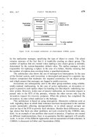
The registers used by a standard IBM-AT class hard disk controller are shown in Fig. 3-23.
Figure 3-23. (a) The control registers of an IDE hard disk controller. The numbers in parentheses are the bits of
the logical block address selected by each register in LBA mode. (b) The fields of the Select Drive/Head register.
Register Read Function Write Function
0 Data Data
1 Error Write Precompensation
2 Sector Count Sector Count
3 Sector Number (0-7) Sector Number (0-7)
4 Cylinder Low (8-15) Cylinder Low (8-15)
5 Cylinder High (16-23) Cylinder High (16-23)
6 Select Drive/Head (24-27) Select Drive/Head (24-27)
7 Status Command
(a)
7 6 5 4 3 2 1 0
1 LBA 1 D HS3 HS2 HS1 HS0
LBA: 0 = Cylinder/Head/Sector Mode
1 = Logical Block Addressing Mode
D: 0 = master drive
15
15
Simpo PDF Merge and Split Unregistered Version -
1 = slave drive
HSn: CHS mode: Head select in CHS mode
LBA mode: Block select bits 24 - 27
(b)
We have mentioned several times reading and writing to I/O ports, but we tacitly treated them just like
memory addresses. In fact, I/O ports often behave differently from memory addresses. For one thing, input
and output registers that happen to have the same I/O port address are not the same register. Thus, the data
written to a particular address cannot necessarily be retrieved by a subsequent read operation. For example,
the last register address shown in Fig. 3-23 shows the status of the disk controller when read and is used to
issue commands to the controller when written to. It is also common that the very act of reading or writing an
I/O device register causes an action to occur, independently of the details of the data transferred. This is true
of the command register on the AT disk controller. In use, data are written to the lower-numbered registers to
select the disk address to be read from or written to, and then the command register is written last with an
operation code. The data written to the command register determines what the operation will be. The act of
writing the operation code into the command register starts the operation.
[Page 297]
It is also the case that the use of some registers or fields in the registers may vary with different modes of
operation. In the example given in the figure, writing a 0 or a 1 to the LBA bit, bit 6 of register 6, selects
whether CHS (Cylinder-Head-Sector) or LBA (Logical Block Addressing) mode is used. The data written to
or read from registers 3, 4, and 5, and the low four bits of register 6 are interpreted differently according to the
setting of the LBA bit.
Now let us take a look at how a command is sent to the controller by calling com_out (line 12947). This
function is called after setting up a cmd structure (with do_transfer, which we saw earlier). Before changing
any registers, the status register is read to determine that the controller is not busy. This is done by testing the
STATUS_BSY bit. Speed is important here, and normally the disk controller is ready or will be ready in a
short time, so busy waiting is used. On line 12960 w_waitfor is called to test STATUS_BSY. W_waitfor uses
a kernel call to ask the system task to read an I/O port so w_waitfor can test a bit in the status register. It loops
until the bit is ready or until there is a timeout. The loop is programmed for a quick return when the disk is
ready. Thus the returned value will be true with the minimum possible delay if the controller is ready, true
after a delay if it is temporarily unavailable, or false if it is not ready after the timeout period. We will have
more to say about the timeout when we discuss w_waitfor itself.
A controller can handle more than one drive, so once it is determined that the controller is ready, a byte is
written to select the drive, head, and mode of operation (line 12966) and w_waitfor is called again. A disk
drive sometimes fails to carry out a command or to properly return an error codeit is, after all, a mechanical
device that can stick, jam, or break internallyand as insurance a sys_setalarm kernel call is made to have
the system task schedule a call to a wakeup routine. Following this, the command is issued by first writing all
the parameters to the various registers and finally writing the command code itself to the command register.
This is done with a sys_voutb kernel call, which sends a vector of (value, address) pairs to the system task.
The system task writes each value to the I/O port specified by the address in order. The vector of data for the
sys_voutb call is constructed by use of a macro, pv_set, which is defined in include/minix/devio.h. The act
of writing the operation code to the command register makes the operation begin. When it is complete, an
interrupt is generated and a notification message is sent. If the command times out the alarm will expire and a
synchronous alarm notification will wake up the disk driver.
16
16
Simpo PDF Merge and Split Unregistered Version -
[Page 298]
The next several functions are short. W_need_reset (line 12999) is called when timeouts occur while waiting
for the disk to interrupt or become ready. The action of w_need_reset is just to mark the state variable for
every drive in the wini array to force initialization on the next access.
W_do_close (line 13016) has very little to do for a conventional hard disk. Additional code is needed to
support CD-ROMs.
Com_simple is called to issue controller commands that terminate immediately without a data transfer phase.
Commands that fall into this category include those that retrieve the disk identification, setting of some
parameters, and recalibration. We saw an example of its use in w_identify. Before it is called the command
structure must be correctly initialized. Note that immediately after the call to com_out a call to at_intr_wait is
made. This eventually does a receive which blocks until a notification arrives signifying that an interrupt
has occurred.
We noted that com_out does a sys_setalarm kernel call before asking the system task to write the
registers which set up and execute a command. As we mentioned in the overview section, the next receive
operation normally should receive a notification indicating an interrupt. If an alarm has been set and no
interrupt occurs, the next message will be a SYN_ALARM. In this case w_timeout line 13046 is called. What
needs to be done depends on the current command in w_command. The timeout might have been left over
from a previous operation, and w_command may have the value CMD_IDLE, meaning the disk completed its
operation. In that case there is nothing to do. If the command does not complete and the operation is a read or
write, it may help to reduce the size of I/O requests. This is done in two steps, first reducing the maximum
number of sectors that can be requested to 8, and then to 1. For all timeouts a message is printed and
w_need_reset is called to force re-initialization of all drives on the next attempted access.
When a reset is required, w_reset (line 13076) is called. This function makes use of a library function,
tickdelay, that sets a watchdog timer and then waits for it to expire. After an initial delay to give the drive time
to recover from previous operations, a bit in the disk controller's control register is strobedthat is, set to a
logical 1 level for a definite period, then returned to the logical 0 level. Following this operation, w_waitfor is
called to give the drive a reasonable period to signal it is ready. In case the reset does not succeed, a message
is printed and an error status returned.
Commands to the disk that involve data transfer normally terminate by generating an interrupt, which sends a
message back to the disk driver. In fact, an interrupt is generated for each sector read or written. The function
w_intr_wait (line 13123) calls receive in a loop, and if a SYN_ALARM message is received w_timeout is
called. The only other message type this function should see is HARD_INT. When this is received the status
register is read and ack_args is called to reinitialize the interrupt.
[Page 299]
W_intr_wait is not called directly; when an interrupt is expected the function called is the next one,
at_intr_wait (line 13152). After an interrupt is received by at_intr_wait a quick check is made of the drive
status bits. All is OK if the bits corresponding to busy, write fault, and error are all clear. Otherwise a closer
look is taken. If the register could not be read at all, it is panic time. If the problem was a bad sector a specific
error is returned, any other problem results in a general error code. In all cases the STATUS_ADMBSY bit is
set, to be reset later by the caller.
We have seen several places where w_waitfor (line 13177) is called to do busy waiting on a bit in the disk
controller status register. This is used in situations where it is expected the bit might be clear on the first test,
and a quick test is desirable. For the sake of speed, a macro that read the I/O port directly was used in earlier
versions of MINIXthis is, of course, not allowable for a user-space driver in MINIX 3. The solution here is to
17
17
Simpo PDF Merge and Split Unregistered Version -
use a do while loop with a minimum of overhead before the first test is made. If the bit being tested
is clear there is an immediate return from within the loop. To deal with the possibility of failure a timeout is
implemented within the loop by keeping track of clock ticks. If a timeout does occur w_need_reset is called.
The timeout parameter that is used by the w_waitfor function is defined by DEF_TIMEOUT_TICKS on line
12228 as 300 ticks, or 5 seconds. A similar parameter, WAKEUP (line 12216), used to schedule wakeups
from the clock task, is set to 31 seconds. These are very long periods of time to spend busy waiting, when you
consider that an ordinary process only gets 100 msec to run before it will be evicted. But, these numbers are
based upon the published standard for interfacing disk devices to AT-class computers, which states that up to
31 seconds must be allowed for a disk to "spin up" to speed. The fact is, of course, that this is a worst-case
specification, and that on most systems spin up will only occur at power-on time, or possibly after long
periods of inactivity, at least for hard disks. For CD-ROMs or other devices which must spin up frequently
this may be a more important issue.
There are a few more functions in at_wini.c. W_geometry returns the logical maximum cylinder, head, and
sector values of the selected hard disk device. In this case the numbers are real ones, not made up as they were
for the RAM disk driver. W_other is a catch-all for unrecognized commands and ioctls. In fact, it is not used
in the current release of MINIX 3, and we should probably have removed it from the Appendix B listing.
W_hw_int is called when a hardware interrupt is received when it is not expected. In the overview we
mentioned that this can happen when a timeout expires before an expected interrupt occurs. This will satisfy a
receive operation that was blocked waiting for the interrupt, but the interrupt notification may then be
found by a subsequent receive. The only thing to be done is to reenable the interrupt, which is done by
calling the next function, ack_irqs (line 13297). It cycles through all the known drives and uses the
sys_irqenable kernel call to ensure all interrupts are enabled. Finally, at the end of at_wini.c two strange
little functions are found, strstatus and strerr. These use macros defined just ahead of them on lines 13313 and
13314 to concatenate error codes into strings. These functions are not used in MINIX 3 as described here.
[Page 300]
3.7.6. Floppy Disk Handling
The floppy disk driver is longer and more complicated than the hard disk driver. This may seem paradoxical,
since floppy disk mechanisms are simpler than those of hard disks, but the simpler mechanism has a more
primitive controller that requires more attention from the operating system. Also, the fact that the medium is
removable adds complications. In this section we will describe some of the things an implementer must
consider in dealing with floppy disks. However, we will not go into the details of the MINIX 3 floppy disk
driver code. In fact, we have not listed the floppy disk driver in Appendix B. The most important parts are
similar to those for the hard disk.
One of the things we do not have to worry about with the floppy driver is the multiple types of controller to
support that we had to deal with in the case of the hard disk driver. Although the high-density floppy disks
currently used were not supported in the design of the original IBM PC, the floppy disk controllers of all
computers in the IBM PC family are supported by a single software driver. The contrast with the hard disk
situation is probably due to lack of motivation to increase floppy disk performance. Floppy disks are rarely
used as working storage during operation of a computer system; their speed and data capacity are too limited
compared to those of hard disks. Floppy disks at one time were important for distribution of new software and
for backup, but as networks and larger-capacity removable storage devices have become common, PCs rarely
come standard with a floppy disk drives any more.
The floppy disk driver does not use the SSF or the elevator algorithm. It is strictly sequential, accepting a
request and carrying it out before even accepting another request. In the original design of MINIX it was felt
that, since MINIX was intended for use on personal computers, most of the time there would be only one
18
18
Simpo PDF Merge and Split Unregistered Version -
process active. Thus the chance of a disk request arriving while another was being carried out was small.
There would be little to gain from the considerable increase in software complexity that would be required for
queueing requests. Complexity is even less worthwhile now, since floppy disks are rarely used for anything
but transferring data into or out of a system with a hard disk.
That said, the floppy driver, like any other block driver, can handle a request for scattered I/O. However, in
the case of the floppy driver the array of requests is smaller than for the hard disk, limited to the maximum
number of sectors per track on a floppy diskette.
[Page 301]
The simplicity of the floppy disk hardware is responsible for some of the complications in floppy disk driver
software. Cheap, slow, low-capacity floppy drives do not justify the sophisticated integrated controllers that
are part of modern hard drives, so the driver software has to deal explicitly with aspects of disk operation that
are hidden in the operation of a hard drive. As an example of a complication caused by the simplicity of
floppy drives, consider positioning the read/write head to a particular track during a SEEK operation. No hard
disk has ever required the driver software to explicitly call for a SEEK. For a hard disk the cylinder, head, and
sector geometry visible to the programmer often do not correspond to the physical geometry. In fact, the
physical geometry may be quite complicated. Typically there are multiple zones (groups of cylinders) with
more sectors per track on outer zones than on inner ones. This is not visible to the user, however. Modern hard
disks accept Logical Block Addressing (LBA), addressing by the absolute sector number on the disk, as an
alternative to cylinder, head, and sector addressing. Even if addressing is done by cylinder, head, and sector,
any geometry that does not address nonexistent sectors may be used, since the integrated controller on the disk
calculates where to move the read/write heads and does a seek operation when required.
For a floppy disk, however, explicit programming of SEEK operations is needed. In case a SEEK fails, it is
necessary to provide a routine to perform a RECALIBRATE operation, which forces the heads to cylinder 0.
This makes it possible for the controller to advance them to a desired track position by stepping the heads a
known number of times. Similar operations are necessary for the hard drive, of course, but the controller
handles them without detailed guidance from the device driver software.
Some characteristics of a floppy disk drive that complicate its driver are:
Removable media.1.
Multiple disk formats.2.
Motor control.3.
Some hard disk controllers provide for removable media, for instance, on a CD-ROM drive, but the drive
controller is generally able to handle any complications without support in the device driver software. With a
floppy disk, however, the built-in support is not there, and yet it is needed more. Some of the most common
uses for floppy disksinstalling new software or backing up filesare likely to require switching of disks in and
out of the drives. It will cause grief if data intended for one diskette are written onto another. The device
driver should do what it can to prevent this. This is not always possible, as not all floppy drive hardware
allows determination of whether the drive door has been opened since the last access. Another problem that
can be caused by removable media is that a system can become hung up if an attempt is made to access a
floppy drive that currently has no diskette inserted. This can be solved if an open door can be detected, but
since this is not always possible some provision must be made for a timeout and an error return if an operation
on a floppy disk does not terminate in a reasonable time.
[Page 302]
19
19
Simpo PDF Merge and Split Unregistered Version -
Removable media can be replaced with other media, and in the case of floppy disks there are many different
possible formats. IBM compatible hardware supports both 3.5-inch and 5.25-inch disk drives and the diskettes
can be formatted in a variety of ways to hold from 360 KB up to 1.2 MB (on a 5.25-inch diskette) or 1.44 MB
(on a 3.5-inch diskette).
MINIX 3 supports seven different floppy disk formats. Two possible solutions are possible for the problem
this causes. One way is to refer to each possible format as a distinct drive and provide multiple minor devices.
Older versions of MINIX did this. Fourteen different devices were defined, ranging from /dev/pc0, a 360 KB
5.25-inch diskette in the first drive, to /dev/PS1, a 1.44 MB 3.5-inch diskette in the second drive. This was a
cumbersome solution. MINIX 3 uses another method: when the first floppy disk drive is addressed as
/dev/fd0, or the second as /dev/fd1, the floppy disk driver tests the diskette currently in the drive when it is
accessed, in order to determine the format. Some formats have more cylinders, and others have more sectors
per track than other formats. Determination of the format of a diskette is done by attempting to read the higher
numbered sectors and tracks. By a process of elimination the format can be determined. This takes time, but
on modern computers only 1.44 MB 3.5-inch diskettes are likely to be found, and this format is probed first.
Another possible problem is that a disk with bad sectors could be misidentified. A utility program is available
for testing disks; doing so automatically in the operating system would be too slow.
The final complication of the floppy disk driver is motor control. Diskettes cannot be read or written unless
they are revolving. Hard disks are designed to run for thousands of hours on end without wearing out, but
leaving the motors on all the time causes a floppy drive and diskette to wear out quickly. If the motor is not
already on when a drive is accessed, it is necessary to issue a command to start the drive and then to wait
about a half second before attempting to read or write data. Turning the motors on or off is slow, so MINIX 3
leaves a drive motor on for a few seconds after a drive is used. If the drive is used again within this interval,
the timer is extended for another few seconds. If the drive is not used in this interval, the motor is turned off.
20
20
Simpo PDF Merge and Split Unregistered Version -