PROGRAMMING AND CUSTOMIZING THE PIC MICROCONTROLLER 3rd phần 3 ppsx
Bạn đang xem bản rút gọn của tài liệu. Xem và tải ngay bản đầy đủ của tài liệu tại đây (1.9 MB, 130 trang )
THE EMU-II 233
Msg3 ; Introductory Message
dw 0x02280,0x03A6E,0x03965,0x013A0,0x013C8,0x03320,0x0396F,0x021A0
dw 0x036EF,0x030ED,0x0326E,0x06F3,0x0A
Msg4 ; “Help” Message
dw 0x03454,0x01065,0x037C3,0x036ED,0x03761,0x039E4,0x030A0,0x032F2
dw 0x06BA
dw 0x0100A,0x01048,0x0102D,0x032C8,0x0386C,0x050D
dw 0x02220,0x016A0,0x02220,0x03BEF,0x0366E,0x030EF,0x01064,0x03841
dw 0x03670,0x031E9,0x03A61,0x037E9,0x06EE
dw 0x0100A,0x01021,0x0225B,0x020FC,0x0105D,0x0102D,0x032D2,0x032F3
dw 0x01074,0x03474,0x01065,0x036C5,0x03675,0x03A61,0x03265,0x02820
dw 0x037F2,0x032E3,0x039F3,0x0396F,0x029AF,0x03A65,0x03A20,0x032E8
dw 0x02820,0x0294F,0x020D4,0x02A20,0x03879,0x06E5
dw 0x0100A,0x018DB,0x02DA0,0x03241,0x03964,0x039E5,0x02EF3,0x0105D
dw 0x0102D,0x034D3,0x033EE,0x032EC,0x029A0,0x032F4,0x01070,0x03966
dw 0x036EF,0x03A20,0x032E8,0x021A0,0x03975,0x032F2,0x03A6E,0x02820
dw 0x01043,0x03241,0x03964,0x039E5,0x01073,0x0396F,0x029A0,0x032F0
dw 0x034E3,0x034E6,0x03265,0x020A0,0x03264,0x032F2,0x039F3,0x050D
dw 0x02520,0x02DA0,0x03241,0x03964,0x039E5,0x02EF3,0x016A0,0x029A0
dw 0x03769,0x03667,0x01065,0x03A53,0x03865,0x0252F,0x036F5,0x01070
dw 0x03B4F,0x03965,0x021A0,0x03661,0x0106C,0x03A53,0x03A61,0x036E5
dw 0x03765,0x06F4
dw 0x0100A,0x01047,0x020DB,0x03264,0x032F2,0x039F3,0x0105D,0x0102D
dw 0x03A53,0x03961,0x01074,0x03841,0x03670,0x031E9,0x03A61,0x037E9
dw 0x0106E,0x03C45,0x031E5,0x03A75,0x03769,0x06E7
dw 0x0100A,0x01049,0x03241,0x03964,0x039E5,0x01073,0x0102D,0x032D3
dw 0x01074,0x03474,0x01065,0x03749,0x03A73,0x03AF2,0x03A63,0x037E9
dw 0x0106E,0x037D0,0x03769,0x032F4,0x01072,0x050D
dw 0x02920,0x016A0,0x02220,0x039E9,0x03670,0x03CE1,0x03A20,0x032E8
dw 0x02820,0x034F2,0x030ED,0x03CF2,0x029A0,0x032F0,0x034E3,0x03661
dw 0x02320,0x03775,0x03A63,0x037E9,0x0106E,0x032D2,0x034E7,0x03A73
dw 0x03965,0x06F3
dw 0x0100A,0x01053,0x032D2,0x020E7,0x03264,0x032F2,0x039F3,0x016A0
dw 0x029A0,0x037E8,0x01077,0x037C3,0x03A6E,0x03765,0x039F4,0x037A0
dw 0x01066,0x01B31,0x02920,0x033E5,0x039E9,0x032F4,0x039F2,0x029A0
dw 0x030F4,0x03A72,0x03769,0x01067,0x03A61,0x03A20,0x032E8,0x029A0
dw 0x032F0,0x034E3,0x034E6,0x03265,0x020A0,0x03264,0x032F2,0x039F3
dw 0x050D
dw 0x022A0,0x02920,0x033E5,0x03241,0x03964,0x039E5,0x01073,0x0102D
dw 0x037CC,0x03261,0x03A20,0x032E8,0x02920,0x033E5,0x039E9,0x032F4
dw 0x01072,0x034F7,0x03474,0x03720,0x03BE5,0x02220,0x03A61,0x06E1
dw 0x0100A,0x01042,0x020DB,0x03264,0x032F2,0x039F3,0x0105D,0x0102D
dw 0x037D4,0x033E7,0x032EC,0x03A20,0x032E8,0x02120,0x032F2,0x035E1
dw 0x037F0,0x03769,0x01074,0x03241,0x03964,0x039E5,0x06F3
dw 0x0100A,0x01043,0x0102D,0x03643,0x030E5,0x01072,0x03661,0x0106C
dw 0x03474,0x01065,0x03942,0x030E5,0x0386B,0x034EF,0x03A6E,0x06F3
dw 0x0100A,0x01055,0x020DB,0x03264,0x032F2,0x039F3,0x0105D,0x0102D
dw 0x034C4,0x03873,0x030EC,0x01079,0x01A32,0x02620,0x03769,0x039E5
dw 0x037A0,0x01066,0x03749,0x03A73,0x03AF2,0x03A63,0x037E9,0x039EE
Simpo PDF Merge and Split Unregistered Version -
234 EMULATORS AND DEBUGGERS
dw 0x050D
dw 0x015AA,0x02DA0,0x03241,0x03964,0x039E5,0x02EF3,0x016A0,0x020A0
dw 0x03264,0x024A0,0x039EE,0x03974,0x031F5,0x034F4,0x0376F,0x01073
dw 0x037F4,0x03A20,0x032E8,0x02820,0x037F2,0x03967,0x036E1,0x026A0
dw 0x036E5,0x0396F,0x06F9
dw 0x0150A,0x01050,0x022DB,0x0237C,0x0105D,0x0102D,0x03950,0x033EF
dw 0x030F2,0x0106D,0x022C5,0x02950,0x026CF,0x037A0,0x01072,0x03646
dw 0x039E1,0x01068,0x024D0,0x036C3,0x031E9,0x037F2,0x026A0,0x02AC3
dw 0x050D
dw 0x02B2A,0x016A0,0x02B20,0x03965,0x03369,0x01079,0x03474,0x01065
dw 0x037C3,0x03A6E,0x03765,0x039F4,0x037A0,0x01066,0x03474,0x01065
dw 0x024D0,0x036C3,0x031E9,0x037F2,0x026A0,0x02AC3,0x050D
dw 0x00
;#CompStart
Admittedly, this is a lot harder to understand than the ASCII text above (especially
with the high order byte having to be shifted down by seven to read it), but it cuts the
instruction requirements in half for the application text files.
DT Compress is a Windows GUI application that simply allows a user to select an
assembler (.asm) file and then converts it into a compressed include (.inc) file.
Depending on the amount of text to compress, the application may take a few seconds
to run (it takes five seconds to do the EMU-II compress.asm file on my 300 MHz
Pentium-II PC).
To read and output the compressed file, I created the subroutine:
SendMsg ; Call Here for sending a specific
; message string to the Serial port.
; The Message Number is in “w”
movwf MsgTemp ^ 0x0100 ; Save the Message Number
clrf MsgOffset ^ 0x0100 ; Reset the
clrf (MsgOffset + 1) ^ 0x0100
clrf SMCount ^ 0x0100 ; Clear Count of Output Bytes
MT_Loop1 ; Loop Here Until “MsgTemp” is == 0
movf MsgTemp ^ 0x0100, f ; Is “MsgTemp” Equal to Zero?
btfsc STATUS, Z
goto MT_Loop2 ; Yes, Start Displaying Data
bcf STATUS, C ; Calculate Address of Next Word to
rrf (MsgOffset + 1) ^ 0x0100, w ; Display
addlw HIGH MsgTable
movwf EEADRH ^ 0x0100
rrf (MsgOffset + 1) ^ 0x0100, w ; Setup Carry Correctly for
rrf MsgOffset ^ 0x0100, w ; Increment
addlw LOW MsgTable
movwf EEADR ^ 0x0100
btfsc STATUS, C
incf EEADRH ^ 0x0100, f ; If Carry Set, Increment to Next Page
EEPReadMacro ; Now, Do the Program Memory Read
Simpo PDF Merge and Split Unregistered Version -
THE EMU-II 235
rlf EEDATA ^ 0x0100, w ; Start with the Odd Byte
rlf EEDATH ^ 0x0100, w
btfss MsgOffset ^ 0x0100, 0 ; Odd or Even Byte?
movf EEDATA ^ 0x0100, w ; Even Byte
andlw 0x07F ; Convert to ASCII 7 Bits
btfsc STATUS, Z
decf MsgTemp ^ 0x0100, f ; Decrement the Value Count
incf MsgOffset ^ 0x0100, f ; Point to the Next Byte in the String
btfsc STATUS, Z
incf (MsgOffset + 1) ^ 0x0100, f
goto MT_Loop1
MT_Loop2 ; Have Correct Offset, Now, Display the
; Message
bcf STATUS, C ; Calculate Address of Next Word to
rrf (MsgOffset + 1) ^ 0x0100, w ; Display
addlw HIGH MsgTable
movwf EEADRH ^ 0x0100
rrf (MsgOffset + 1) ^ 0x0100, w ; Setup Carry Correctly for
rrf MsgOffset ^ 0x0100, w ; Increment
addlw LOW MsgTable
movwf EEADR ^ 0x0100
btfsc STATUS, C
incf EEADRH ^ 0x0100, f ; If Carry Set, Increment to Next Page
EEPReadMacro ; Now, Do the Program Memory Read
rlf EEDATA ^ 0x0100, w ; Start with the Odd Byte
rlf EEDATH ^ 0x0100, w
btfss MsgOffset ^ 0x0100, 0 ; Odd or Even Byte?
movf EEDATA ^ 0x0100, w ; Even Byte
andlw 0x07F ; Convert to ASCII 7 Bits
btfsc STATUS, Z
goto MT_End ; Zero, Yes
SendCharMacro
incf MsgOffset ^ 0x0100, f ; Point to the Next Byte in the String
btfsc STATUS, Z
incf (MsgOffset + 1) ^ 0x0100, f
incf SMCount ^ 0x0100, f
goto MT_Loop2
MT_End ; Finished sending out the Table Data
movf SMCount ^ 0x0100, w ; Return the Number of Bytes Sent
EmuReturn
In this code there are three macros. The EEPReadMacro (along with the
EEPWriteMacro) is used to access the Flash program memory of the PIC16F87x.
SendCharMacro is used to poll the UART transmit holding register empty interrupt
request flag (TXIF of PIR1) and send the byte when the holding register is open. The
macro code is:
Simpo PDF Merge and Split Unregistered Version -
236 EMULATORS AND DEBUGGERS
SendCharMacro Macro
bcf STATUS, RP1
ifndef Debug
btfss PIR1, TXIF
goto $ - 1
else
goto $ + 3 ; Put in a Skip over the “nop” to save
nop ; a Mouse Click
endif
movwf TXREG ; Send the Byte
bcf PIR1, TXIF ; Reset the Interrupt Request Flag
bsf STATUS, RP1
endm
and it should be noted that if the label Debug is defined, the polling loop is ignored
because in MPLAB, the USART hardware is not simulated and execution will never fall
out of this loop.
There are two other things to notice about this macro. The first is in the code that exe-
cutes when the Debug label is defined. I kept two instructions to match the btfss/goto
instructions of the polling loop, but I jump over the second one to save a mouse click
when I’m single-stepping through the application. This might seem like a petty place to
save a mouse click or two, but SendCharMacro is used a lot in this application, and
when single-stepping through the application, skipping over the instructions seems to
reduce the number of mouse clicks significantly.
The second point to notice about this macro is that it changes the operating bank from
2 to 0 and then back to 2. The EMU-II application has all its variables in Banks 2 and
3 of the PIC microcontroller. This allows the user to access almost all the registers
(except for the USART specific ones) in Banks 0 and 1 without affecting the operation
of the EMU-II in any way.
Instead of using the call and return instructions in the EMU-II, I used two
macros, EmuCall and EmuReturn, which I wrote to implement a subroutine call that
does not access the built-in program counter stack. The reason for writing these sub-
routines was to avoid the possibility that the subroutine calls in the EMU-II application
code would affect the emulated application.
The EmuCall and EmuReturn macros are:
EmuCall Macro Address ; Stackless Emulator Call
local ReturnAddr
movwf tempw ^ 0x0100 ; Save the Call Value in “w”
incf FSR, f
movlw LOW ReturnAddr ; Setup the Return Address
movwf INDF
incf FSR, f
movlw HIGH ReturnAddr
movwf INDF
movlw HIGH Address ; Jump to the Specified Address
movwf PCLATH
Simpo PDF Merge and Split Unregistered Version -
THE EMU-II 237
movf tempw ^ 0x0100, w ; Restore “w” before doing it
goto (Address & 0x07FF) | ($ & 0x01800)
ReturnAddr
movf tempw ^ 0x0100, w ; restore the “w” from the Subroutine
endm
EmuReturn Macro ; Return from the Macro Call
movwf tempw ^ 0x0100 ; Save the Temporary “w” Register
movf INDF, w ; Get the Pointer to the Return Address
movwf PCLATH
decf FSR, f ; Point to the Low Byte of the
; Return Address
movf INDF, w
decf FSR, f
movwf PCL ; Jump to the Return Address
endm
This will save the return address in a data stack implemented with the FSR register.
This address is then used to return to the calling section of code.
These macros are reasonably efficient, but it should be noted that they do affect the
state of the zero flag in the STATUS register and they do take up a number of instruc-
tions. The number of instructions taken up by the subroutine calls is why I created other
macros, like EEPReadMacro and SendCharMacro, which actually require fewer
instructions to implement the required function than the EmuCall macro.
The last aspect of the application that I would like to bring to your attention is how
I implemented the breakpoints for application single-stepping and breakpoints. As I
pointed out above, if I were to use multiple instructions for breakpoints, then code like:
btfss PIR1, TXIF ; Poll until USART Free to Send a
goto $ - 1 ; Character
movwf TXREG ; Output the character in “w”
will not be able to be stepped through.
The approach I took was to create a single-step (and breakpoint) mechanism that would
not have problems with these situations. By limiting application size to one page, I can
use a single goto instruction for implementing the return to the EMU-II application
code.
For example, if I was single-stepping at the btfss instruction in the example above,
the EMU-II code would put in the breakpoints shown below:
btfss PIR1, TXIF ; Poll until USART Free to Send a
goto NextStep ; Was “goto $ - 1”
goto SecondStep ; Was “movwf TXREG”
Now, depending on the value of TXIF, execution will return to the EMU-II code via
the goto NextStep or goto SecondStep, which in either case is located in the
instruction code area 0x700 to 0x7FF. NextStep and SecondStep are separate
Simpo PDF Merge and Split Unregistered Version -
238 EMULATORS AND DEBUGGERS
from each other in order for the correct new program counter value to be noted and
recorded by the EMU-II application.
The NextStep, SecondStep, and breakpoint code is similarly designed and uses
the following instructions:
Step # ; “#” is from 0 to 8 for Breakpoints
movwf _w ; Save the “w” Register
movf STATUS, w ; Save STATUS and Change to Bank 2
bsf STATUS, RP1 ; Execute from Page 2 in EMU-II
bcf STATUS, RP0
movwf _status ^ 0x100
movf PCLATH, w ; Save the PCLATH Registers
movwf _pclath ^ 0x100
movlw # * 2 ; Save the Breakpoint Number
gotom StopPoint
AddressIns #
dw 0x3FFF ; Address of the Breakpoint/Single Step
dw 0x3FFF ; Instruction at Breakpoint/Single Step
The two words at the end of the breakpoint are used to save the address where the
breakpoint was stored and the original instruction. The breakpoint address is used to
update the EMU-II’s program counter along with replacing the goto Step # instruction
with the application’s original instruction.
Before any type of execution, all the enabled breakpoints are put into the application pro-
gram memory. Upon completion of execution, the application program memory is scrubbed
for all cases of breakpoint gotos and they are restored with the original instructions.
Note that when setting up single-step breakpoints, the next instruction or destination
of a goto or call is given the goto NextStep and goto SecondStep break-
points. This is possible for all instructions instead of return, retlw, and retfie.
The reason for these three instructions to get an error message during single-stepping
is that the destination cannot be taken from the processor stack. Instead of putting a break-
point at potentially every address in the application, I decided to simply prevent single-
stepping at these instructions.
As applications may be halted by pressing the Reset button in the application, when
the EMU-II first boots up, the scrub operation takes place to ensure that there are not
any invalid gotos left in the application.
There are a few things to watch out for with breakpoints and interrupts. For most appli-
cation debugging, I do not recommend setting breakpoints within the interrupt handler.
The reason for this is to avoid any missed interrupt requests or having multiple requests
queued up in such a way that the application’s mainline never returns. I originally
thought that this was a limitation of the EMU-II, but I tried some experiments with
MPLAB-ICD and found that it also has similar issues. Interrupt handlers should always
be debugged as thoroughly as possible using a simulator so as to not miss or overflow
on any interrupt events and requests.
This is not to say that simple applications (such as just waiting for a TMR0 overflow)
cannot be used with the EMU-II. In testing out the application, I did work through a
Simpo PDF Merge and Split Unregistered Version -
THE EMU-II 239
number of experiments with interrupt handlers without problems. There is one point
I should make clear to you: breakpoints should never be enabled in both an interrupt
handler and mainline code. If an interrupt breakpoint is executed while a mainline
breakpoint is being handled by the EMU-II, the mainline breakpoint context registers
will be changed to the values of the interrupt handler. The execution of the application
may also become erratic.
If you are debugging an application that requires breakpoints in both the interrupt han-
dler and mainline code, I recommend setting only one at a time and using the C (break-
point all clear) command before setting the next breakpoint.
The Emu-II includes a simple disassembler for reviewing the source code. A typical
unassembled application is shown in Fig. 5.15, and there are two things I want to point
out about the disassembled function.
The first point to make about the disassembled code is the lack of useful labels. If
you were to look at the disassembled code you would see that constant and variable
names are not output which makes it much more difficult to read.
movlw 0x0FF
movwf PORTB ; Turn off all the LED’s
clrf PORTA ; Use PORTA as the Input
bsf STATUS, RP0 ; Have to go to Page 0 to set Port
; Direction
Note “TMR0”
- Should be “OPTION_REG”
Figure 5.15 EMU-II unassembly display showing how a Bank 1 register is
displayed with a Bank 0 label.
Simpo PDF Merge and Split Unregistered Version -
240 EMULATORS AND DEBUGGERS
clrf TRISB & 0x07F ; Set all the PORTB bits to Output
movlw 0x0D2 ; Setup the Timer to fast count
; Put in Divide by 8 Prescaler for 4x
movwf OPTION_REG & 0x07F ; Clock
bcf STATUS, RP0 ; Go back to Page 0
movlw TRISA ; Have to Set/Read PORTA.0
movwf FSR
Loop:
bsf PORTA, 0 ; Charge Cap on PORTA.0
bcf INDF, 0 ; Make PORTA.0 an Output
movlw 0x0100 - 10 ; Charge the Cap
clrf TMR0 ; Now, Wait for the Cap to Charge
Sub_Loop1: ; Wait for the Timer to Reach 10
movf TMR0, w ; Get the Timer Value
btfss STATUS, Z ; Has the Timer Overflowed?
goto Sub_Loop1 ; No, Loop Around again
bsf INDF, 0 ; Now, Wait for the Cap to Discharge
clrf TMR0 ; and Time it.
Sub_Loop2: ; Just wait for PORTA.1 to go Low
btfsc PORTA, 0
goto Sub_Loop2
comf TMR0, w ; Get the Timer Value
This is an excellent example of why I prefer only using source code enabled develop-
ment tools. Trying to get the function of the application from Fig. 5.15 is just about impos-
sible, but when you look at the source, the function that it implements—potentiometer
measuring code with an RC delay circuit—is quite obvious.
The second problem with what is pointed out in Fig. 5.15 is that the disassembler
doesn’t know what bank is currently executing. In Fig. 5.15, you should see that the
TRISB register, when it is enabled for all output, is referenced as PORTB (line 5 of the
code). This is not a big problem and one that I can usually work my way through
without any problems.
What I find to be very confusing in Fig. 5.15 is the identification of TMR0 when I want
OPTION_REG (or OPTION as it is displayed by the EMU-II). As you step through the
application, you will discover that the instruction on the prompt line will display the
instruction based on the state of the RP0 bit of the emulated device’s STATUS register.
While application code can be downloaded to the Emu-II, it cannot be uploaded into
a PC. This was specifically not implemented to discourage the practice of modifying
an application in the emulator and then uploading the hex file into the host PC and repli-
cating the application from this source. This is a very dangerous practice and should be
avoided at all costs to prevent the proliferation of executable code without supporting
application code.
Simpo PDF Merge and Split Unregistered Version -
OTHER EMULATORS 241
The Emu-II is probably the most involved application that you will find in this book.
I am pleased with the way it came out and it is a very interesting project and tool to have
while learning about the PIC microcontroller. I don’t think that it is adequate as a pro-
fessional development tool due to the lack of a source code interface, but for very
simple applications this emulator can be an invaluable tool for you to learn about the
PIC microcontroller.
Other Emulators
While there are a number of very good PIC microcontroller emulators designed and mar-
keted by third parties, there hasn’t been the same explosion of designs as with PIC micro-
controller programmers by hobbyists. The reason for this really comes down to the
complexity of work required to develop an emulator circuit along with the difficulty of
developing a user interface for them. The Emu-II is a very simple example of how an
emulator could work with a very basic user interface that does not contain many of the
features I would consider critical for using an emulator in a professional environment.
A professional product would require a bondout chip and a source/listing file
interface for the user to use it effectively. Other features would include providing a
high-speed interface to avoid the time required to download application hex files into
the Emu-II.
If you are interested in designing your own full emulator, you will have to talk to your
local Microchip representative to find out about entering into a nondisclosure agreement
(NDA) with them to learn more about the options Microchip has for developing emu-
lators for their products. Microchip does make bondout chips available for all of the PIC
microcontroller part numbers, but technical information about them is considered pro-
prietary and not for general release.
Partial emulators (like the Emu-II) are still a lot of work to get running, but
designing them gives you a much better appreciation of how the PIC microcontroller
works. If you are interested in designing your own, please take a look at the code
in the Emu-II to see how the various issues of executing an application from within
a PIC microcontroller monitor are handled.
Having said there are few commercial emulators available, I should point out that there
are a number of products you can buy. These commercial emulators provide wide ranges
of services and can be bought for a few hundred dollars up to $1,000 or more for a full
bondout chip-based complete system.
Simpo PDF Merge and Split Unregistered Version -
This page intentionally left blank
Simpo PDF Merge and Split Unregistered Version -
243
6
THE MICROCHIP PIC MCU
PROCESSOR ARCHITECTURE
When starting to research a new device, whether it is a microcontroller such as one of the
many PIC
®
MCU part numbers or a simple logic gate, one of the first things that you have
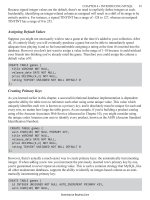
for reference information is the block diagram. A well-drawn block diagram, such as the
one taken from the PIC16C61 microcontroller datasheet in Fig. 6.1, actually has all the infor-
mation that you need to understand and start working with the chip. Unfortunately, block
diagrams can be intimidating and confusing when you look at them for the first time. I dare
say that many people will skip right over them without spending any time trying to under-
stand how data flows and what features are available on the chip, and this is unfortunate
because there is a wealth of information that will help you to visually understand and
remember how the chip works and allow you to follow the flow of data through the chip.
The purpose of this chapter is to help you to understand how programs execute and
manipulate data in the PIC microcontroller’s processor. To do this, I am going to rely
on the block diagram that is available in each of the PIC MCU datasheets. I have found
that this is a very useful way of going about the task of learning about the processor and
how it works because the diagram is an architectural drawing of its inner workings. When
you understand the block diagram, you will understand how each instruction executes,
and this will give you some insights into how to structure your assembly-language pro-
grams so that they are as efficient as possible.
The processor block diagrams are very similar for each of the PIC microcontroller
processor families (consisting of the low-end, mid-range, PIC17, and PIC18 architectures),
and for this reason, I will explain the mid-range devices in detail and then review the archi-
tectural differences in the other PIC MCU families. These differences mainly center on how
data is accessed in different register banks, how intrapage jumps and calls are executed, and
how data is indexed and stored in stacks. Even without these sections explaining the differ-
ences in the mid-range PIC microcontroller architecture, you should be able to understand
how these processors work by reviewing the block diagram at the start of the datasheets.
Copyright © 2008, 2002, 1997 by The McGraw-Hill Companies, Inc. Click here for terms of use.
Simpo PDF Merge and Split Unregistered Version -
244 THE MICROCHIP PIC MCU PROCESSOR ARCHITECTURE
The CPU
In the microchip datasheets you will find that the PIC microcontroller’s processor is
described as a “RISC-like architecture . . . separate instruction and data memory (Harvard
architecture).” In this chapter I want to explain what this means for people who do not
have Ph.D.s in computer architectures, as well as help explain how application code exe-
cutes in the PIC MCU processor. The processor may seem to be very complex and dif-
ferent from other devices you’ve worked with before, but I believe that it is very
intelligently designed and works in a very logical manner. Despite the complex written
description of the processor, you will discover that it is actually quite straightforward
and designed to simplify the implementation of many complex applications and pro-
gramming algorithms.
The PIC microcontroller processor can be thought of as being built around the arithmetic/
logic unit (ALU), which provides basic arithmetic and bitwise operations for the processor.
There are a number of specific-use registers that control operation of the CPU as well
as input/output (I/O) registers and data-storage (RAM) registers. In this book I call the
EPROM
RAM
Program
memory
1K × 14
8 Level Stack
(13 bit)
File
Registers
36 × 8
RAM Addr <9>†
Addr Mux
Indirect
Addr <8>
Direct Addr <7>
Program
Bus <14>
Instruction Reg.
Mux
3
ALU
W Reg
Timer 0
V
DD
,
MCLR
† Higher order bits are from STATUS register
OSC1/
CLKIN
OSC2/
CLKOUT
Instruction
Decode &
Control
Power-up
Timer
Oscillator
Start-up Time
Power-on
Reset
Watchdog
Timer
Timing
G
eneration
V
SS
FSR
STATUS Reg
Program Counter
13 Data Bus <8> Port A
Port B
RA0-RA3
RA4/T0CKI
RB0/INT
RB1/RB7
Figure 6.1 PIC16C61 block diagram.
Simpo PDF Merge and Split Unregistered Version -
THE CPU 245
specific-use registers hardware registers or I/O registers depending on the function
they perform. The hardware registers also allow direct manipulation of functions that
usually are invisible to the programmer, such as the program counter, to allow for
advanced program functions. Data-storage (RAM or variable) registers are called file
registers by Microchip.
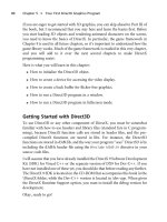
The registers are completely separate from the program memory and are said to be
in their own “spaces.” This is known as Harvard architecture and is shown in Fig. 6.2.
In the figure, note that the program memory and the hardware to which it is connected
are completely separate from the register space. This allows program memory reads for
instructions to take place while the processor is accessing data and processing it. This
capability allows the PIC microcontroller to execute software faster than many of its
contemporaries.
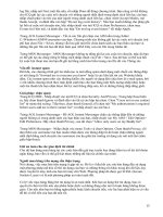
Instruction execution takes place over four clock cycles, as shown in Fig. 6.3. During
an instruction execution cycle, the next instruction to be executed is fetched from pro-
gram memory. When the next instruction is executing, the processor is fetching the next
instruction after it. After an instruction has been fetched and is latched in a
Figure 6.2 Harvard architecture block
diagram.
Q1 - Latch in Fetched Instruction
- Increment PC
Q2 - Input Register/Data Load
Q3 - Operation
Q4 - Result Save
1 Instruction Cycle
Figure 6.3 Four clock cycles, each performing its
own task, make up a single instruction cycle.
Simpo PDF Merge and Split Unregistered Version -
246 THE MICROCHIP PIC MCU PROCESSOR ARCHITECTURE
holding/decode register, the program counter (used to address which instruction is being
executed) is incremented. This is known as Q1. Next (Q2), data to be processed (often
with the data in the accumulator or “working” register, which will be described below)
is read and put into temporary buffers. During Q3, the data-processing operation takes
place. Finally, the resulting data value is stored during Q4, after which the process
repeats itself for the next instruction (which is put into the holding register while the
current instruction is executing). These four cycles that take place with each “tick” of
the clock are known collectively as an instruction cycle.
Since the instruction cycle is made up of the four Q cycles, which is equivalent to
four clock cycles, the instruction execution speed is said to be one-quarter the clock
speed. For example, an application that has a 4-MHz clock would be running 1 million
instruction cycles per second (MIPS). In the PIC18 processors, there is a built-in phased-
locked loop circuitry that multiplies the external clock’s speed four times. This means
that for PIC18 chips with the phased-locked loop active, the instruction cycle is equal
to the chip’s clock.
There are three primary methods of accessing data in the PIC microcontroller. Direct
addressing means that the register address within the register bank (explained below)
is specified in the instruction. If a constant is going to be specified, then it is specified
immediately in the instruction. The last method of addressing is to use an index register
that points to the address of the register to be accessed. Indexed addressing is used
because the address to be accessed can be changed arithmetically. In other processors,
there are additional methods of addressing data, but in the PIC microcontroller, these
are the only three.
When accessing registers in the mid-range PIC microcontrollers directly, 7 address
bits are explicitly defined as part of the instruction. These 7 bits result in the ability to
specify up to 128 addresses in an instruction, as shown in Fig. 6.4.
Figure 6.4 Basic PIC microcontroller processor
architecture.
Simpo PDF Merge and Split Unregistered Version -
THE CPU 247
These 128 register addresses are known as a bank. To expand the register space
beyond 128 addresses for hardware and variable registers, Microchip has added the capa-
bility of accessing multiple banks of registers, each capable of registering 128 addresses
in the mid-range PIC microcontrollers. The low-end PIC microcontrollers can access
32 registers per bank, also with the opportunity of having four banks accessible by
processor for up to 128 register addresses in total. This will be explained later in this
chapter, along with how register addressing is implemented for the PIC17C and PIC18C
processors.
The ALU shown in Fig. 6.4 is an acronym for the arithmetic/logic unit. This circuit
is responsible for doing all the arithmetic and bitwise operations, as well as the condi-
tional instruction skips implemented in the PIC microcontroller’s instruction set. Every
microprocessor available today has an ALU that integrates these functions into one
block of circuits. The ALU will be discussed later in this chapter.
The program counter maintains the current program instruction address in the pro-
gram memory (which contains the instructions for the PIC microcontroller processor,
each one of which is read out in sequence and stored in the instruction reg and then
decoded by the instruction decode and control circuitry.
The program memory contains the code that is executed as the PIC microcontroller
application. The contents of the program memory consist of the full instruction at each
address (which is 12 bits for the low-end, 14 bits for the mid-range and 16 bits for both
the PIC17 and PIC18 devices). This differs from many other microcontrollers in which
the program memory is only 8 bits wide, and instructions that are larger than 8 bits are
read in subsequent reads. Providing the full instruction in program memory and reading
it at the same time result in the PIC microcontroller being somewhat faster in instruction
fetches than other microcontrollers.
The block diagram in Fig. 6.4, while having 80 percent or more of the circuits needed
for the PIC microcontroller’s processor is not a viable processor design in itself. As drawn
in Fig. 6.4, there is no way to pass data to the program memory for immediate addressing,
and there is no way to modify the program counter. As I work through this chapter,
I will be fleshing out Fig. 6.4 until it is a complete processor that can execute PIC
microcontroller instructions.
To implement two-argument operations, a temporary holding register, often known
as an accumulator, is required to save a temporary value while the instruction fetches
data from another register or is passed a constant value from the instruction. In the PIC
microcontroller, the accumulator is known as the working register or, more commonly,
as the w register. The w register really cannot be accessed directly as a register address
in itself in the low-end and mid-range PIC microcontrollers. Instead, the contents must
be moved to other registers that can be accessed directly. The w register can be accessed
as an addressed register in the PIC17 and PIC18 devices. Every arithmetic operation that
takes place in the PIC microcontroller uses the w register. If you want to add the con-
tents of two registers together, you would first move the contents of one register into
the w register and then add the contents of the second to it.
The PIC microcontroller architecture is very powerful from the perspective that the
result of this operation can be stored either in the w register or the source of the data.
Simpo PDF Merge and Split Unregistered Version -
248 THE MICROCHIP PIC MCU PROCESSOR ARCHITECTURE
Storing the result back into the source effectively eliminates the need for an additional
instruction for saving the result of the operation. There is a lot of flexibility in how instruc-
tions are executed to provide arithmetic and bitwise operations for an application.
Adding the w register changes how the ALU is wired in the PIC microcontroller
processor block diagram, as shown in Fig. 6.5. Note that the ALU has changed to a device
with two inputs (which is the case in the actual PIC microcontroller’s ALU) and that
the contents of the w register are used as one of the inputs. You also should note that
when a result is passed from the ALU, it could either be stored into the w register or in
one of the file registers. This is a bit of foreshadowing of one of the most important fea-
tures of the PIC microcontroller architecture and how instructions execute.
Figure 6.5 shows the PIC microcontroller at its simplest level. This simple circuit can
execute well over half the PIC microcontroller’s instructions.
Hardware and File Registers
If you have worked with other processors and computer systems, you probably will be
surprised by the close coupling and shared memory space of the PIC microcontroller’s
processor’s registers, hardware I/O registers, and variable RAM. This is a result of the
small (5-bit addressing for low-end devices and 7-bit addressing for mid-range devices)
register space accessible to the processors. Despite being somewhat unusual, this close
coupling of registers for both variable storage and hardware I/O registers provides you
with a common means of accessing, processing, and updating the contents of registers,
regardless of their function, using a single set of tools.
In the mid-range PIC microcontroller, each instruction that accesses a register contains
the addresses within the given bank with a maximum bank size of 7 bits, which allows
up to 128 different addresses. In each bank, the registers fall within four distinct groups:
Figure 6.5 PIC microcontroller processor archi-
tecture with the w register and file registers as
source and destination for ALU operations.
Simpo PDF Merge and Split Unregistered Version -
HARDWARE AND FILE REGISTERS 249
■
Processor registers
■
I/O hardware registers
■
Variable memory
■
Shared or “shadowed” variable memory
The processor registers consist of STATUS, PCL, PCLATH (from mid-range devices),
FSR, INDIF, and WREG (for high-end devices). These registers are always at the same
addresses within the different PIC microcontroller families. These addresses are listed
in Table 6.1. These registers can be accessed from within any of the register banks.
The I/O hardware registers consist of the OPTION, TMRO, PORT, I/O PINS and
enable registers, INTCON, and other interrupt control and flag registers, along with any
other hardware features built into the particular PIC microcontroller. The important
difference between these registers and processor registers is that except for INTCON,
these registers are bank-specific, and while some conventions are used for the placement
of these functions, for part numbers, and for specific functions, the registers are located
in different addresses. The registers with conventions are listed in Table 6.2.
As time goes on and more features become standard, you’ll probably see the mid-range
PIC microcontrollers standardize on a 32-byte processor and I/O hardware register block
(also known as the special function registers, or SFRs) at the start of each bank.
Above the processor and I/O hardware registers, are the file registers, or variable
memory. This memory can be bank-specific or shared between banks. In all PIC micro-
controllers, there are a number of bytes that are always available (shared, or what I call
shadowed) across all the register banks. This memory is used to pass data between the
banks or, as I prefer to use them, to provide a common variable for sharing context reg-
ister data during interrupts without having to change the bank specification in the status
register. The shared memory is PIC microcontroller part number–specific and can be
common across all banks or pairs of banks.
In the low-end PIC microcontrollers, many devices have multiple banks, but these
multiple banks are strictly for providing additional file registers. Normally in these
TABLE 6.1 BASE REGISTER ADDRESSES BY PIC MICROCONTROLLER
ARCHITECTURE FAMILY
REGISTER LOW-END MID-RANGE PIC17 PIC18
WREG Not accessible Not accessible 0x0A 0xFE8
STATUS 0x03 0x03 0x04/0x06 0xFD8
PCL 0x02 0x02 0x02 0xFF9
PCLATH Page bits in 0x0A 0x0e 0xFFB/0xFFA
STATU S
FSR 0x04 0x04 0x01/0x09 0xFEA-0xFE9
INDF 0x00 0x00 0x00/0x08 0xFEF
Simpo PDF Merge and Split Unregistered Version -
250 THE MICROCHIP PIC MCU PROCESSOR ARCHITECTURE
PIC MCUs, the first 16 addresses of each bank (address 0 to 0x00F) are common, with
the upper 16 bytes of each bank having file registers that are specific to them.
BANK ADDRESSING
One of the most difficult concepts for most people to understand when they first start
working with PIC microcontrollers is the register banks used in the different PIC micro-
controller architectures. The number of registers available for direct addressing in the
PIC microcontroller is limited to the number of address bits in the instruction that are
devoted to specifying register access. In low-end PIC microcontrollers there are only
5 bits (for a total of 32 registers per bank), whereas in mid-range PIC microcontrollers
there are 7 bits available for a total of 128 registers per bank. The PIC18 can access
256 register addresses, but each bank is 128 registers in size.
In order to provide additional register addresses, Microchip has introduced the con-
cept of banks for the registers. Each bank consists of an address space consisting of the
maximum size allowable by the number of bits provided for the address. When a mid-range
application is executing, it is executing out of a specific bank, with the 128 registers
devoted to the bank directly accessible.
In each PIC microcontroller, a number of common hardware registers are available
across all the banks. For mid-range devices, these registers are INDF and FSR, STATUS,
INTCON (presented later), PCL, and PCLATH (also discussed later). These registers
can be accessed regardless of the bank that has been selected. Other hardware registers
may be common across all or some of the banks as well. In all mid-range PIC micro-
controllers there are common file registers that are common across banks to allow data
to be transferred across them.
TABLE 6.2 I/O REGISTER ADDRESSES BY PIC MICROCONTROLLER
ARCHITECTURE FAMILY
REGISTER LOW-END MID-RANGE PIC17 PIC18
OPTION Uses OPTION 0x81 0x05 0xFD0
Instruction
TMR0 0x01 0x01 0x0B/0x0C 0xFD7/0xFD6
PORTC-PORTA 0x07–0x05 0x07–0x05 Varies by part 0xF82–0xF80
number
TRISC-TRISA Uses TRIS port 0x87–0x85 Varies by part 0xFD4–0xFD2
Instruction number
PORTD/TRISD Not available 0x08/0x88 Varies 0xF83/0xFD5
PORTE/TRISE Not available 0x09/0x89 Varies 0xF84/0xFD6
INTCON Not available 0x0B 0x07 0xFF2
OSCCAL 0x05 Varies by part Not available Varies by part
number number
Simpo PDF Merge and Split Unregistered Version -
HARDWARE AND FILE REGISTERS 251
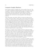
In Fig. 6.6, the PIC16C84’s register space is shown for bank 0 and bank 1. When exe-
cution has selected bank 0, the PORTA and PORTB registers can be addressed directly.
When bank 1 is selected, the TRISA and TRISB registers are accessed at the same
address as PORTA and PORTB when bank 0 is selected.
To change the current bank out of which the mid-range application is executing, the RPx
bits of the STATUS register are changed. To change between bank 0 and bank 1 or bank
2 and bank 3, RP0 is modified. Another way of looking at RP0 is that it selects between
odd and even banks. RP1 selects between the upper (bank 2 and bank 3) and lower (bank
0 and bank 1) bank pairs. For most of the basic mid-range PIC microcontroller applica-
tions presented in this book, you will only be concerned with bank 0 and bank 1 and RP0.
At the risk of getting ahead of myself, the TRIS registers are used to specify the input
or output operation of the I/O port bits. When one of the TRIS register bits is set, the
corresponding PORT bit is in input mode. When the TRIS bit is reset, then the PORT
bit is in output mode. To access the PORT bits, bank 0 must be selected, and to access
the TRIS bits, bank 1 must be selected.
For example, to set PORTB bit 0 as an output and load it with a 1, the PIC micro-
controller code would execute as
PORTB.Bit0 = 1; // Load PORTB.Bit0 with a “1”
STATUS.RP0 = 1; // Start Executing out of
Bank 1
TRISB.Bit0 = 0; // Make PORTB.Bit0 Output
STATUS.RP0 = 0; // Resume Execution in Bank 0
Microchip specifies that bank 1 registers are defined with the same address as bank 0
registers but with bit 7 set in their address specification. This means that for the mid-range
PIC microcontrollers, bank 0 register addresses are in the range of 0 to 0x7F, whereas
Bank 0
Bank 1
Shaded areas indicate
unused registers
- 0x000 Returned
when these
registers are
read
Addr - Reg Addr - Reg
00 - INDF
01 - TMRO
02 - PCL
03 - STATUS
04 - FSR
05 - PORTA
06 - PORTB
07 -
08 - EEDATA
09 - EEADR
0A - PCLATH
0B - INTCON
0C - 4F Shared
- File Regs
50 - 7F
- Unused
80 - INDF
81 - OPTION
82 - PCL
83 - STATUS
84 - FSR
85 - TRISA
86 - TRISB
87 -
88 - EECON1
89 - EECON2
8A - PCLATH
8B - INTCON
8C - CF Shared
- File Regs
D0 - FF
- Unused
Figure 6.6 PIC16F84 register map.
Simpo PDF Merge and Split Unregistered Version -
252 THE MICROCHIP PIC MCU PROCESSOR ARCHITECTURE
bank 1 register addresses are in the range of 0x80 to 0xFF. Once the RP0 bit is set to
select the appropriate bank, the least significant 7 bits of the address are used to access
a specific register. This can be very confusing—the reason for having this specification
is the FSR (index pointer) register, which is 8 bits in size. The FSR can access registers
in both banks transparently. The Microchip TRISB register has the address value 0x86,
which has bit 7 set and is in bank 1. PORTB has an address value of 0x006 and can only
be accessed when bank 0 is selected.
When you start working with more complex mid-range PIC microcontrollers, which
use all four banks, you will see registers with address bit 8 set, which indicates that the
registers are in banks 2 and 3. These registers are accessed directly using the RP1 bit
(along with RP0), and the least significant 7 bits of the Microchip-specified address are
used as the address.
Specifying an address with bit 7 (or 8) set will result in the following message:
Register in operand not in bank 0. Ensure that bank bits are correct.
This indicates that an invalid register address has been specified and to make sure that
execution is in the correct bits. Most people clear bits 7 and 8 of the defined register
address to avoid this message. This can be done by simply ANDing the address with
0x7F to clear bit 7, but a somewhat more sophisticated operation normally is performed
on the address to make sure that the register is accessed from the correct bank. Instead
of ANDing with 0x7F to clear bit 7 for bank 1, the address is XORed with 0x80. By
doing this, if the register is supposed to be in bank 1 (bit 7 of the address is set), then it
will be cleared. If the register can only be accessed in bank 0 (bit 7 of the address is
reset), then this operation will result in bit 7 being set and will cause the preceding mes-
sage to be given. This is a nice way to ensure that you are not accessing registers that
are not in the currently selected bank.
Using the XOR operation, the preceding example becomes
PORTB.Bit0 = 1; // Load PORTB.Bit0 with a “1”
STATUS.RP0 = 1; // Start Executing out of
// Start Bank 1
(TRISB ^ 0x080).Bit0 = 0; // Make PORTB.Bit0 Output
STATUS.RP0 = 0; // Resume Execution in Bank 0
This is also true for banks 2 and 3, which have address bit 8 set. In Table 6.3 I have
listed the value of the XOR registers for specific banks. If the error message comes out
of the register access, then you will know that you are accessing a register in the wrong
bank. Note that the INDF, PCL, STATUS, FSR, PCLATH, and INTCON registers are
common across all the banks and do not have to have their addresses XORed with a con-
stant value to be accessed correctly.
Direct bank addressing is a very confusing concept and, unfortunately, very impor-
tant to PIC microcontroller application development. I realize that it probably will be
difficult for you to understand exactly what I am saying here, but it will become clearer
as you work through the example application code.
Simpo PDF Merge and Split Unregistered Version -
HARDWARE AND FILE REGISTERS 253
The index register (FSR), as I indicated earlier, is 8 bits in size, and its bit 7 is used
to select between the odd and even banks (bank 0 and bank 2 versus bank 1 and bank 3).
Put another way, if bit 7 of the FSR is set, then the register being pointed to is in the
odd register bank. This straddling of the banks makes it very easy to access different
banks without changing the RP0 bit. For the preceding example, if I were to use the FSR
register to point to TRISB instead of accessing it directly, I could use the code
PORTB.Bit0 = 1; // Load PORTB.Bit0 with a “1”
FSR = TRISB; // FSR Points to TRISB
INDF.Bit0 = 0; // Make PORTB.Bit0 Output
This ability of the mid-range FSR register to access both banks 0 and 1 is why I rec-
ommend that for many applications array variables should be placed in odd banks, and
single-element variables should be placed in even banks. Of course, this is only possible
if the entire file register range is not “shadowed” across the banks as in the PIC16F84 and
other simple mid-range PIC microcontrollers that are used in introductory applications.
To select between the high and low banks with the FSR, the IRP bit of the STATUS
register is used. This bit is analogous to the RP1 bit for direct addressing. Having sep-
arate bits for selecting between the high and low bank pairs means that data can be trans-
ferred between banks using direct and index addressing without having to change the
bank-select bits for either case.
There is one thing that I have to note with regard to the FSR register and indirect
addressing. Even though the FSR register can access 256 different register addresses
across two banks, it cannot be used to access more than 128 file registers contiguously
(or all in a row). The reason for this is the control registers contained at the first few
addresses of each bank. If you try to wrap around a 128-byte bank, you will corrupt the
PIC microcontroller’s control registers with disastrous results.
ZERO REGISTERS
I don’t really know if this qualifies as a feature, but unused registers in a PIC micro-
controller’s register map will return 0 (0x00) when they are read. This capability can
be useful in some applications. Zero registers (undefined registers that return 0 when
TABLE 6.3 BANK ADDRESS TO “RPX” BIT SETTINGS
BANK RP1 RP0 ADDRESS RANGE XOR VALUE
0 0 0 0x0–0x7F None
1 0 1 0x80–0xFF 0x80
2 1 0 0x100–0x17F 0x100
3 1 1 0x180–0x1FF 0x180
Simpo PDF Merge and Split Unregistered Version -
254 THE MICROCHIP PIC MCU PROCESSOR ARCHITECTURE
read) are normally defined in the Microchip documentation as shaded addresses in the
device register map documentation.
In Fig. 6.6, the PIC16F84’s register map is shown with addresses 7 (PORTC regis-
ters) in each bank shaded, indicating that they return 0 when read. Of course, when these
registers are written to, their values are lost and not stored in the register. (One might
say the information has gone to the “great bit bucket in the sky.”)
I am hesitant to recommend using the zero registers when programming. It is impor-
tant to note that in different PIC microcontrollers, the zero registers are at different loca-
tions. Because of this, if code is transferred directly from one application to another and
the zero register chosen is not available in the PIC MCU destination (e.g., a valid file
or hardware register is at this location), then the code will not work correctly. Instead
of using a hardware zero register, I would recommend that a file register be defined and
cleared for the purpose of always returning 0.
The PIC Microcontroller’s ALU
The arithmetic/logic unit, which is labeled ALU in the PIC microcontroller block
diagrams, performs arithmetic, bitwise, and shifting operations on 1 or 2 bytes of data
at a time. These three simple functions have been optimized to maximize the per-
formance of the PIC microcontroller and minimize the cost of building the MCUs.
An in-depth understanding of the ALU’s function is not critical to developing appli-
cations for the PIC microcontroller; however, having an idea of the tradeoffs that
were made in designing the ALU will give you a better idea of how PIC microcon-
troller instructions execute and what is the best way to create your applications. In
this discussion of how the PIC microcontroller’s ALU operates and is designed, I have
been able to encompass 27 of the 37 instructions available in the mid-range PIC
microcontroller processor. Twenty-five years ago, when the PIC microcontroller was
first developed, any savings in circuits used in the ALU (or anywhere else in the
device) paid huge dividends in the final cost of manufacturing the device. This phi-
losophy has been embraced in the ALUs used in the different PIC microcontroller
processor architectures.
I tend to think of the ALU as a number of processor operations that execute in par-
allel with a single multiplexer that is used to select which result is to be used by the appli-
cation. Graphically, this looks like the block diagram shown in Fig. 6.7. The STATUS
register stores the results of the operations and will be described in more detail in the
next section. The ALU is the primary modifier of the STATUS bits that are used to record
the result of operations, as well as providing input to the data shift instructions.
The circuit shown in the block diagram Fig. 6.7 certainly would work as drawn, but it
would require a large number of redundant circuits. Many of these functions could be com-
bined into a single circuit by looking for opportunities such as noting that an Increment
is addition by one and combining the two functions. A list of arithmetic and bitwise func-
tions available within the PIC microcontroller, along with the combinations necessary to
provide the full range of arithmetic operations, can be found in Table 6.4.
Simpo PDF Merge and Split Unregistered Version -
THE PIC MICROCONTROLLER’S ALU 255
As can be seen in this table, the 12 operations could be reduced to 6 basic operations
with the constants 1 and 0xFF provided as extra inputs along with immediate and reg-
ister data. Note that the basic bitwise operations (AND, OR, XOR, Shift left,
and Shift right) do not have equivalencies, but this is not a problem because they
are usually simple functions to implement in logic. This is not true for the arithmetic
operations. For example, instead of providing a separate subtractor, the ALU’s adder
Input “A” Input “B”
STATUS
Result
Adder Subtractor L-Shift R-Shift
Multiplexor
Figure 6.7 Multiplexor used to select arithmetic/bitwise
operation result to output from the PIC microcontroller
processor ALU.
TABLE 6.4 AVAILABLE PIC MICROCONTROLLER ALU OPERATIONS
OPERATION EQUIVALENT OPERATION
Move AND with 0xFF
Addition None
Subtraction Addition to value XORed with 0xFF and incremented
Negation XOR with 0xFF and increment
Increment Addition with one
Decrement Addition with 0xFF
AND None
OR None
XOR None
Compl
ement XOR with 0xFF
Shift left None
Shift right None
Simpo PDF Merge and Split Unregistered Version -
256 THE MICROCHIP PIC MCU PROCESSOR ARCHITECTURE
could be used with the addition of some simple circuits to provide an addition and sub-
traction capability, as shown in Fig. 6.8.
I have used Subtract as an example here because it is an instruction that you
probably will learn to hate as you start working with the PIC microcontroller. The
reason for the problems with subtraction is because the result of the operation probably
won’t make sense to you unless you look at how the operation is carried out and how
the hardware is implemented, as shown in Fig. 6.7. I will go through the subtraction
instructions in more detail in the next chapter, but to introduce subtraction and help show
how the PIC microcontroller’s ALU works, I wanted to show how an adder with a few
additional circuits could be used to provide addition and subtraction instructions using
only an incrementer and a selectable negation circuit. The other instructions in the PIC
microcontroller work as you would expect, and optimization of the ALU does not result
in any other nonconventional instruction execution.
The circuit in Fig. 6.7 could be enhanced further by selecting between 0 (0x00) and
the basic ALU Input B selection. The circuit then looks like Fig. 6.9, which can do addi-
tion, subtraction, incrementing, and decrementing. Incrementing and decrementing are
carried out by selecting the 0 input and then either incrementing it (to add one to the
Input A) or decrementing it (adding 0xFF or –1 to Input A). When Microchip engineers
designed the PIC microcontroller’s ALU, they used tricks such as this to avoid having
to add redundant circuitry to the chip.
As with many microcontrollers, the PIC microcontroller instruction set has the capa-
bility of modifying and testing individual bits in registers. These instructions are not as
clever as you may think and are, in fact, implemented with the base hardware I’ve
described in this section. A bit Set instruction simply ORs a register with a value that
has the appropriate bit set. A bit Clear (or Reset) instruction ANDs the contents of
a register with a byte that has all the bits set except for the one to be cleared. I’m mentioning
Input “A” Input “B”
Complement
Incrementer
Result
STATUS
Multiplexor
Adder
Figure 6.8 Combining operations to provide
addition, subtraction, incrementing, and decre-
menting with a single adder.
Simpo PDF Merge and Split Unregistered Version -
THE PIC MICROCONTROLLER’S ALU 257
this here because it is important to realize that entire registers are read in, modified by
the AND/OR functions, and then written back to the register. As I will show later in this
book, not being aware of the method used in the PIC microcontroller for setting and
clearing bits can result in some vexing problems when some applications execute.
THE STATUS REGISTER
The STATUS register is the primary central processing unit (CPU) execution control
register used for recording the results of arithmetic and bitwise operations and allowing
the use of this data to control the execution of application code. The operation results
bit register is common to all computer processors, but the PIC microcontroller is some-
what unique in that it makes the data available to the application code, and it is used
directly (not indirectly in some instructions) for program execution control. The STATUS
register’s organization is different in each of the PIC microcontroller architectures, but
they all have the same 3 bits of data after arithmetic and bitwise operations. The 3 bits
(or flags) that are set or reset depending on the result of the arithmetic or bitwise oper-
ation are the carry, digit carry, and zero bits. These bits are often referred to as the
execution status flags (Z, DC, and C).
The zero flag (Z) is set when the result of an operation is 0. For example, ANDing
0x5A with 0xA5 is
0x05A AND 0x0A5 = 0b001011010 & 0b010100101
= 0b000000000
which will set the zero flag.
Input “A”
Input “B”
Complement
Incrementer
Result
STATUS
Multiplexor
Adder
0x00
Multiplexor
Figure 6.9 Adding multiple inputs to the Input B
of the ALU adder/subtractor circuit adds the ability
to increment and decrement Input A.
Simpo PDF Merge and Split Unregistered Version -