Kinetics of Materials - R. Balluff_ S. Allen_ W. Carter (Wiley_ 2005) Episode 12 pot
Bạn đang xem bản rút gọn của tài liệu. Xem và tải ngay bản đầy đủ của tài liệu tại đây (3.25 MB, 45 trang )
19
2
HETEROGENEOUS NUCLEATION
481
Homogeneous
0.3
3i
0
0.5
1
1.5“
2
yaa/yap
=
2
cos
l/l
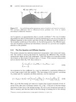
Figure
19.14:
Re imes in which grain corner, edge. boundary, and homogeneous
nucleation are predictecf
to
be dominant.
From
Cahn
[18].
19.2.2
Nucleation on Dislocations
Dislocations in crystals have an excess line energy per unit length that is associated
with the elastic strain field of the dislocation and the bad material in its core. In
many cases, the formation of a particle of the new phase at the dislocation can
reduce this energy, enabling it to act
as
a favorable site for heterogeneous nucleation.
The original treatment of heterogeneous incoherent nucleation on dislocations was
by Cahn [19]. The general topic, including coherent nucleation on dislocations, has
been reviewed by
Larch6
[20].
Incoherent Nucleation.
Consider first incoherent nucleation on dislocations
[
191.
For linearly elastic isotropic materials, the energy per unit length
El
inside a cylin-
der of radius
T
having a dislocation at its center is given by
and
EL
=
-I.(&)
Pb2
(screw dislocation)
4n
Pb2
(edge dislocation)
47~
(1
-
v)
In
(k)
El
=
(19.50)
(19.51)
where
b
is the Burgers vector and
R,
is the usual effective core radius.
Poisson’s ratio
v
is approximately
0.3
for many solids,
so
to a fair approximation,
the energy difference between edge and screw dislocations can be ignored. Following
Cahn.
El=-ln(&)
Bb
2
(19.52)
where
B
x
pbl(2n).
Allowing the entire region inside a radius
T
to transform to incoherent
@
will allow
essentially all of the dislocation energy originally inside the transformed region to
be “released.” Thus, the dislocation catalyzes incoherent nucleation by eliminating
some of the dislocation’s total energy. It is important to note that the dislocation
will still effectively exist in the material along with its strain energy outside the
transformed region, even though the incoherent
@
has replaced the core region. For
example, a Burgers circuit around the dislocation in the matrix material surround-
ing the incoherent @-phase cylinder will still have a closure failure equal to
b.
On
482
CHAPTER
19:
NUCLEATION
forming the incoherent cylinder of radius
r,
the total free energy change per unit
length is
(terms independent of
r)
(19.53)
Bb
2
AG’(r) =m2Ag~+2.1rry-
-lnr+
Extreme values of
AG’(r)
are given by the condition
Bb
br
2r
=
2./r(rAg~
+
7)
-
-
=
0
8
AG‘
(r )
(19.54)
Plotting
AG’(r)
vs.
r
in Fig.
19.15,
two types of behavior are evident, depending
on the value of the parameter,
a,
where
(19.55)
For
a
>
1,
nucleation
is
barrierless-i.e., the transformation is controlled solely by
growth kinetics. However, for
a
c
1,
a
barrier exists. The local minimum of
AG’(r)
at point
A
in the plot corresponds to a metastable cylinder of
p
of radius
ro
forming
along the dislocation line. (In
a
sense, this is analogous to the Cottrell atmosphere
described in Section
3.5.2.)
In Eq.
19.54,
the metastable cylinder’s radius
is
(19.56)
The nucleation barrier for
a
c
1
is then related to the difference in
AG’(r)
between the states
A
and
B
in Fig.
19.15,
where the radius
rc
corresponding to the
unstable state
at
B
is given from Eq.
19.54
as
(19.57)
However, the dislocation is practically infinitely long compared to the size of any
realistic critical nucleus.
If
the nucleus were of uniform radius along a long length
of the dislocation,
AGc
would be very large.
A
critical nucleus will form from
a
local
fluctuation in the form of
a
“bulge” of the cylinder associated with the metastable
state
A,
as
illustrated in Fig.
19.16.
The problem is thus to find the particular
bulged-out shape that corresponds to a
minimum
activation barrier for nucleation.
tl
B
r0
rc
r
Fi
ure
19.16:
cyfndrical precipitate along the core
of
a
dislocation.
From
Cahn
[lQ].
Possible free energy vs. size behavior
for
the formation of
an
incoherent
19
2.
HETEROGENEOUS NUCLEATION
483
Figure
19.16:
dislocation.
Possible shape
for incoherent critical nucleus forming along the core of
a
Let the function
r(t)
specify the shape of the nucleus. The energy to go from
the metastable state
A
to the unstable state
B
(see Fig. 19.15) can be expressed
AG
=
[AG'
(r)
-
AG'
(TO)]
dt
(19.58)
J
From earlier equations,
7rAgB(r2-Tz)
-"I.(:)
2
+2ry
[r/q-rO]}
dt
(19.59)
The unknown shape
r(
t)
is determined by minimizing
AG
using variational calcu-
lus techniques. The solution to the Euler equation
for
this problem is somewhat
complicated, requiring some substitutions and lengthy algebra [19].
From
the re-
sulting equations, one can plot the ratio of the activation barrier for nucleation
on dislocations
AGp
to that for homogeneous nucleation
As:
vs.
a,
in
a
manner
analogous to the plot given in Fig. 19.13, which compared nucleation on various
sites in polycrystals. The resulting plot in Fig. 19.17 shows
a
dramatic decrease in
the relative value
of
AGf
as
cy
-,
1.
Cahn also considered briefly the nucleation kinetics and showed that for reason-
able values of the parameters in the theory, nucleation on dislocations in solids can
be copious [19]. Typically, this occurs when
a
is in the range 0.4-0.7.
"
0
0.2
0.4
0.6
0.8
1.0
a
Figure
19.17:
at dislocations with increasing values
of
the parameter
a
(see
Eq.
19.55).
From
Cahn
[19].
Lowering of the activation barrier for heterogeneous incoherent nucleation
484
CHAPTER
19.
NUCLEATION
Coherent Nucleation.
The elastic interaction between the strain field of the nucleus
and the stress field in the matrix due to the dislocation provides the main catalyzing
force for heterogeneous nucleation of coherent precipitates on dislocations. This
elastic interaction is absent for incoherent precipitates.
For
coherent particles with dilational strains, there is a strong interaction with
the elastic stress field of edge dislocations
[20].
If a particle has a positive dilational
transformation strain
(&
+
E&,
+
&FZ
>
0),
it can relieve some
of
the dislocation’s
strain energy by forming in the region near the core that is under tensile strain.
Conversely, when this strain is negative, the particle will form on the compressive
side. Interactions with screw dislocations are generally considerably weaker, but
can be important for transformation strains with a large shear component. Deter-
minations of the various strain energies use Eshelby’s method of calculating these
quantities
[20].
Bibliography
1.
F.K. LeGoues, H.I. Aaronson, Y.W. Lee, and G.J. Fix. Influence of crystallography
upon critical nucleus shapes and kinetics of homogeneous f.c.c f.c.c. nucleation. I. The
classical theory regime. In
International Conference on Solid-Solid Phase Transfor-
mations,
pages 427-431, Warrendale, PA, 1982. The Minerals, Metals and Materials
Society.
2. D.T. Wu. Nucleation theory.
Solid State Phys.,
50:37-187, 1997.
3. J.W. Christian.
The Theory
of
Transformations
in
Metals and Alloys.
Pergamon
4. K.C. Russell. Linked flux analysis of nucleation in condensed phases.
Acta Metall.,
5. K.C. Russell. Grain boundary nucleation kinetics.
Acta Metall.,
17(8):1123-1131,
6. K.C. Russell. Nucleation in solids: The induction and steady-state effects.
Adv.
7. J.D. Eshelby. On the determination of the elastic field of an ellipsoidal inclusion, and
8.
F.R.N. Nabarro. The influence of elastic strain on the shape of particles segregating
9.
F.
Bitter. On impurities in metals.
Phys. Rev.,
37(11):1527-1547, 1931.
10.
D.M. Barnett, J.K. Lee, H.I. Aaronson, and K.C. Russell. The strain energy
of
coherent ellipsoidal precipitates.
Scnpta Metall.,
8(12):1447-1450, 1974.
11.
S.M.
Allen and J.C. Chang. Elastic energy changes accompanying the gamma-prime
rafting in nickel-base superalloys.
J.
Mater. Res.,
6(9):1843-1855, 1991.
12. J.D. Eshelby. Elastic inclusions and inhomogeneities. In I.N. Sneddon and R. Hill,
editors,
Progress
in
Solid Mechanics,
volume 2, pages 89-140, Amsterdam, 1961.
Nort h-Holland.
13. A.J. Ardell and R.B. Nicholson. On the modulated structure of aged Ni-A1.
Acta
Metall.,
14(10):1295-1310, 1966.
14.
J.K. Lee,
D.M.
Barnett, and H.I. Aaronson. The elastic strain energy of coherent
ellipsoidal precipitates in anisotropic crystalline solids.
Metall. Trans. A,
8(6):963-
970, 1977.
15. H.I. Aaronson and F.K. LeGoues. An assessment of studies on homogeneous diffusional
nucleation kinetics in binary metallic alloys.
Metall. Tk-ans. A,
23(7):1915-1945, 1992.
Press, Oxford, 1975.
16( 5):761-769, 1968.
1969.
Colloid Interface Sci.,
13(3-4):205-318, 1980.
related problems.
Proc. Roy. SOC. A,
241(1226):376-396, 1957.
in an alloy.
Proc. Phys. SOC.,
52(1):90-104, 1940.
EXERCISES
485
16.
17.
18.
19.
20.
J.W. Cahn and J.E. Hilliard. F'ree energy of
a
non-uniform system-111. Nucleation
in
a
two-component incompressible fluid.
J.
Chem. Phys.,
31(3):688-699, 1959.
H.I. Aaronson and J.K. Lee. The Kinetic Equations
of
Solid-rSolid
Nucleation The-
ory
and Comparisons with Experimental Observations, pages
165-229.
The Minerals,
Metals and Materials Society, Warrendale, PA, 2nd edition,
1999.
J.W. Cahn.
Acta Metall.,
4(5):449459, 1956.
J.W. Cahn. Nucleation on dislocations. Acta Metall.,
5(3):16+172, 1957.
F.C.
Larch& Nucleation and precipitation on dislocations. In F.R.N. Nabarro, editor,
Dislocations in
Solids,
volume
4,
pages
137-152,
Amsterdam,
1979.
North-Holland.
The kinetics of grain boundary nucleated reactions.
EXE
RClS
ES
19.1
An equilibrium temperaturecomposition diagram
for
an
A-B
alloy is shown
in Fig.
19.18a.
A nucleation study is carried out
at
800
K
using an alloy
of
30
at.
%
B.
The alloy is initially homogenized
at
1200
K,
then quenched to
800
K
where the steady-state homogeneous nucleation rate is determined to
be
10'
m-3
s-'.
Since
this
rate is
so
small
as
to be barely detectable, it is
desired to change the alloy composition (i-e., increase the supersaturation)
so
that with the same heat treatment the nucleation rate is increased to
1021
m-3
s-l.
Estimate the new alloy composition required to achieve this
at
800
K.
Use the free energy
vs.
composition curves in Fig.
19.18b,
and
assume that the interphase boundary energy per unit area,
7,
is
75
mJ m-2.
List important assumptions in your analysis.
-
3
1200
-
f
ElOOO-
c"
800-
v
-
B
I
I1
I
I1
I
Ill
0 0.2 0.4
0.6 0.8
1
0 0.2
0.4
0.6
0.8
1
Atomic
fraction
B
(4
Atomic
fraction
B
(b)
Figure
19.18:
AgB,
vs.
atomic fraction of component
B
at
T
=
800
K.
(a)
Equilibrium diagram for
A-B
alloy.
(b)
Plot
of
free-energy density,
Solution.
Important assumptions include that the interfacial free energy is isotropic,
that elastic strain energy
is
unimportant, and that the nucleation rates mentioned are for
steady-state nucleation.
The
critical barrier to nucleation,
Ap,,
can be calculated for
the
0.3
atomic fraction
B
alloy using the
tangent-to-curve
construction on the curves
in Fig.
19.18b
to provide the value
AgB
=
-9
x
10'
Jm-3
for the chemical driving
force for this supersaturation at
800
K.
AgC
is given for a spherical critical nucleus by
486
CHAPTER
19:
NUCLEATION
Note that at this temperature,
kT
=
1.38
x
x
800
=
1.10
x
lo-",
50
that
at 800
K
and
XB
=
0.3, AG,
%
79kT.
Based on the criterion that
for
significant
nucleation
AG,
5
76kT
(Section
19.1.7),
it
is reasonable that the nucleation rate is
"barely detectable" in the alloy with
XB
=
0.3.
The steady-state nucleation rate will be proportional to
exp[-AG,/(kT)]
50
we
know
that at 800
K
and
XB
=
0.3,
lo6
=
~'exp(-79) (19.61)
where the constant
C'
is
equal to
NP.2
in the classical theory
for
steady-state nucleation.
We need to find the critical nucleation barrier necessary to achieve the nucleation rate
of
10".
and this will be
or
1
o6
exp( -79)
loz1
exp[ -AG,/(
kT)]
-=
or
-34.54+79=
-
AGc
kT
In
10-l~
=
-79
+
-
kT
(19.62)
(19.63)
and thus
for
the higher nucleation rate
we
must have
AG,
*:
44.5kT
=
4.91
x
lO-"J.
Next, solve for the chemical driving force required to
get
AG,
down to this value, as
follows:
Finally,
use
the free-energy density vs. composition curves and work the tangent-to-
curve construction in reverse. Using the result that
AgB
=
-12
x
107Jm-3,
the
corresponding tangent to the a-phase curve will be at about
33
at.
%
B.
This calculation serves as a good example of the high sensitivity of nucleation rate to
the degree of supersaturation.
19.2
The data below are typical for
a
metal solid solution that can precipitate
a
phase
0
from
a
matrix phase
a.
Assume that the structures of both phases are
such that
0
could
form by coherent homogeneous nucleation
or,
alternatively,
by incoherent homogeneous nucleation. Also, assume that strain energy can
be neglected during incoherent nucleation but must be taken into account
during coherent nucleation. Using the data below, answer the following:
(a)
Below what temperature does
incoherent
nucleation become
thenody-
(b)
Below what temperature does
coherent
nucleation become
thenody-
(c)
Which type
of
nucleation, coherent or incoherent, do you expect to occur
Data
namically possible?
namically possible?
at 510
K?
Justify your answer.
-yc
=
160 mJ m-2
7'
=
800
mJ m-2
AgE
=
2.6
x
lo9
J
m-3
AgB
=
8
x
lo6
(T
-
900K)
J
m
-3
K-'
(coherent interface)
(incoherent interface)
(coherent particle)
(driving force for precipitation)
Solution.
(a) Nucleation becomes thermodynamically possible
if
the thermodynamic driving
For sufficiently large volumes nuclt
force for the transformation is negative.
EXERCISES
487
ated incoherently in the absence of strain energy, and where the interfacial energy
has become unimportant, the total energy change will be negative
if
AgB
<
0.
Therefore, we need
AgB
=
8
x
lo6
(T
-
900
K)
J
m-3
K-’
<
0,
or
T
<
900
K.
(b) For coherent nucleation to be thermodynamically possible,
AgB
+
AgE
<
0.
Therefore, we need
8
x
lo6
(T
-
900
K)
+
2.6
x
lo9
<
0,
or
T
<
575
K.
(c) Assuming that the number of available sites for nucleation is the same for both
coherent and incoherent mechanisms, the nucleation mechanism one expects to
observe will be determined by the critical free-energy barrier,
AG,.
Because the
nucleation rates are proportional to
exp[-AG,/(kT)],
the mechanism with the
lowest value of
AG,
will dominate and be observable
if
AG,
5
76kT,
approxi-
mately.
Assuming spherical nuclei,
A&
=
167ry3/[3(Ags
+
Ag,)’],
where
(19.65)
y
=
yi,
AgE
=
0
y
=
yc,
AgE
#
0
(incoherent nucleation)
(coherent nucleation)
Using the given data, at
T
=
510K, AgB
=
-3.12
x
lo9
Jm-3.
With this,
AGc
=
8.81
x
lO-”J
(incoherent nucleation)
(19.66)
(
AG,
=
2.54
x
lO-”J
(coherent nucleation)
and, similarly,
AGC/(76kT)
=
1.65
>
1
AGC/(76kT)
=
0.475
<
1
(incoherent nucleation)
(coherent nucleation)
(19.67)
Consequently,
coherent
nucleation is expected.
19.3
Martensitic transformations involve a shape deformation that
is
an invariant-
plane strain (simple shear plus a strain normal to the plane of shear). The
elastic coherency-strain energy associated with the shape change is often min-
imized if the martensite forms
as
thin plates lying in the plane of shear. Such a
morphology can be approximated by an oblate spheroid with semiaxes
(r,
r,
c),
with T
>>
c.
The volume
V
and surface area
S
for an oblate spheroid are given
by the relations
(19.68)
V
=
-r
c
and
S
=
2rr2
47r
2
3
The coherency strain energy per unit volume transformed is
Ac
ASE
=
1-
(19.69)
(a)
Find expressions for the size and shape parameters for a coherent critical
nucleus of martensite. Use the data below to calculate values for these
parameters.
(b)
Find the expression for the activation barrier for the formation of a
coherent critical nucleus of martensite. Use the data below to calculate
the value of this quantity.
(c)
Comment on the likelihood of coherent nucleation of martensite under
these conditions.
488
CHAPTER
19:
NUCLEATION
(d)
Make
a
sketch of the free-energy surface
AG(r,
c)
and indicate the loca-
tion of the critical nucleus configuration
(T~,
c,)
on the surface.
Data
AgB
=
-170 MJ m-3
y
=
150 mJ m-'
A
=
2.4
x
lo3
MJ m-3
(chemical driving force at observed transformation
temperature)
(interphase boundary energy per unit area)
(strain energy proportionality factor)
Solution.
(a) Write the
free
energy to form
a
nucleus in the usual way as the sum of
a
bulk
free-energy term, a strain-energy term, and an interfacial-energy term
so
that
(
19.70)
Now
AG
=
AG(c,
T)
and the critical values of
c
and
T
are then found by applying
the simultaneous conditions
4
4
3
3
AG
=
-TT'CA~B
+
-TTC~A
+
2~r'r
Substituting Eq. 19.70 into Eqs. 19.71 and solving for
rC
and cc yields
(19.71)
(19.72)
Using the data provided, these quantities evaluate to
(19.73)
C
T
rC
=
50nm cc
=
1.5nm
-
=
0.035
(b)
Substituting Eqs. 19.72 into Eq. 19.70 then yields
32~ A2y3
AgC
=
-~
(AgB)4
Using the data provided, this quantity
is
equal to
AG,
=
7.8
x
J
(19.74)
(19.75)
(c) Nucleation would proceed at observable rates
if
A&
5
76kT. Assuming
a
nucle-
ation temperature of
350
K,
=
1.6
x
105
(19.76)
7.8
x
J
-
A
Gc
kT
1.38
x
J
K-l
x
350K
which
is
huge compared to 76!
So
homogeneous nucleation would be very unlikely.
Note that the size parameter
rC
is
particularly large and thus the critical nucleus
volume
is
large, consistent with the large value of
A&.
(d) The saddle point on the free-energy surface,
(rC,cc),
is
indicated in Fig. 19.19.
EXERCISES
489
Figure
19.19:
Saddle
point
on
free-energy surface.
19.4
Derive
Eq.
19.22;
i.e.,
1
1
a2A(7~
-= (w)
62
8kT
N=Nc
Solution.
Approximate the curve of
AGN
vs.
n/
in Fig.
19.6
by a circle of radius
R.
Then
kT
=
R
-
(19.77)
Expanding Eq.
19.77
and neglecting the higher-order terms,
1
11
P-mz
The standard expression for the curvature,
1/R,
is
(19.78)
(19.79)
Combining Eqs.
19.78
and
19.79,
the desired result is then obtained.
19.5
Derive
Eq.
19.36
for
the free-energy change due to the annihilation
of
excess
vacancies
at
nucleating incoherent clusters during precipitation.
Hint:
The chemical potential
of
excess vacancies is given by
Eq.
3.66.
Solution.
First, calculate the energy change contributed by the excess vacancies which
are eliminated to relieve the strain due to the dilatation
$1.
If
V
is the cluster volume,
AV
=
3€TIV.
The number of vacancies required is then
N
=
3ETlV/n
and the
free-energy change due to the removal of these vacancies is therefore
(19.80)
Next,
calculate the free-energy change due to the destruction
of
the additional vacancies
which are removed to the point where the rate of buildup of elastic strain due to
their annihilation is just equal
to
the rate at which energy is given up by the vacancy
annihilation.
If
N
vacancies are destroyed in this fashion, the volume of matrix removed
490
CHAPTER
19:
NUCLEATION
is
Nn
and the dilational strain that
is
induced is then
Nn/3V.
Using
Eq.
19.25,
the
strain energy that is created is
(19.81)
The energy released
by
the annihilated vacancies is
As;
=
NkTln(Xv/XGq),
and the
total energy change is then
(19.82)
AG"
is minimized when
aAG"/aN
=
0,
and carrying out this operation, the minimum
value
is
(19.83)
Adding
Eqs.
19.80
and
19.83,
the total energy change (per unit cluster volume) is then
finally
2
(19.84)
3zn 9(1
-
Y)
Ag
=
kTln
n
19.6
Figure
19.20
shows
a
cross section through the center of
a
critical nucleus
that has cylindrical symmetry around the vertical
axis
EF.
AB
and
CD
are
the traces of
flat
facets that possess the interfacial energy (per unit area)
yf,
and AC and
BD
are the traces of the spherical portion of the interface that
possesses the corresponding energy
y.
E
/
F
Figure
19.20:
Critical nucleus shape.
(a)
Construct
a
Wulff plot that is consistent with the critical nucleus shape
(b)
Show that the free energy to form this critical nucleus can be written
(Wulff shape) in Fig.
19.20.
1
AQ,(sphere)
2
A&
=
-
(3
cos
a
-
coS3
a)
(19.85)
where Ag,(sphere) is the free energy to form
a
critical nucleus for the
same transformation but which is spherical and possesses the interfacial
energy
y.
Assume the classical model for the nucleus.
EXERCISES
491
Solution.
(a) The
WulfF
plot in Fig. 19.21 possesses
two
deep
two
low-energy facets.
cusps necessary to produce the
E
/
F
Figure
19.21:
Deeply cusped WulfF
plot.
(b) Standard relationships for volumes and areas show that the volume of the nucleus
is given by
V
=
27rR3 [cosa
-
(c0s3
a)/3]
while the area of the
two
facets is
2rR2
sin2
a
and the area of the spherical portion of the interface is
47rR2 cosa.
The free energy to form the nucleus is therefore
3
)
AgB
+
2rR2
sin2
a
yf
+
4xR2 cos
a
7
(19.86)
But, according to Fig. 19.21,
rf/r
=
cosa
and therefore
(19.87)
Minimizing
A9
with respect to
R
in order to obtain
Ag,
and using the result that
AQ,(sphere)
=
167ry3/
[3(Ag~)~]
we
obtain the result
(19.88)
1
A&(sphere) 2
=
-
(3cosa
-
cos3a)
AGc
19.7
Consider the possible heterogeneous nucleation of a solid phase from a liquid
in a conically shaped pit in the wall of
a
mold
as
illustrated in Fig.
19.22.
Let the energies of the liquid/mold, solid/mold, and liquid/solid interfaces be
rLM,
rSM,
and
rLS,
respectively, and assume that
rSM
=
rLM,
(a)
Using the classical nucleation model, find an expression
for
the critical
free energy for heterogeneous nucleation to occur within the pit, and
compare it to the critical free energy for homogeneous nucleation in
the bulk liquid. Assume that the pit is deep enough to allow
a
critical
heterogeneous nucleus to form within it.
(b)
For the solid, which has nucleated successfully within the pit, to grow
without limit, it must be able to grow out of the pit and expand into the
bulk liquid. Determine how deep the pit must be
so
that this can occur.
492
CHAPTER
19:
NUCLEATION
Figure
19.22:
wall
of
a mold containing a metastable liquid.
Cross
section
of
heterogeneous solid nucleus formed in a conical pit in the
Solution.
(a)
The nucleus may be expected to have the form shown in Fig.
19.22.
It
consists of
a cone with a spherical cap of constant curvature that meets the mold surface at
90"
and therefore satisfies Young's equation for local interfacial equilibrium. The
volume of the nucleus is then the volume of the cone of height
d
plus the volume
of the spherical cap of radius
R
and is given by
The area of the cap,
A,
is given by
2rRh,
where
h
is its height. Therefore,
A
=
2rRh
=
2rR2[1
-
COS(CY/~)] (19.90)
The free energy to form a nucleus as in Fig.
19.22
is then
(19.91)
2r~3
AG
=
-[1
-
COS(CY/~)]A~~
+
2rR2[1
-
COS(CY/~)]~~~
3
The critical nucleus radius,
Rc,
is found by setting
=
0,
with the result
(19.92)
'-
AgB
The critical radius given by Eq.
19.92
is equal to the critical radius for homogeneous
nucleation in the bulk liquid. This is the expected result because
Y~~
=
Y
SM
(so
that the liquid/solid interface makes an angle of
90"
with the mold) and the
inward pressure on the interface due to curvature,
AP
=
2rLS/R
(Eq.
12.4),
is then exactly balanced by the change in bulk free energy across the interface,
nphase
trans
=
-AgB
(Eq.
12.1).
Substitution of Eq.
19.92
into Eq.
19.91
yields
the critical free energy for nucleation:
27LS
R
-_-
(19.93)
AG,"
=
(16~/3)(y~~)~/(Ag~)~
is the critical free energy of homogeneous nucle-
ation,
so
AG,
1
-
COS(CY/~)
AG,H
-
2
(19.94)
EXERCISES
493
and thus the heterogeneous nucleation will be much easier than homogeneous
nucleation.
(b) Once the critical nucleus has formed within the pit,
it
will grow outward as shown
in Fig.
19.23.
When
it
reaches the mold surface,
at
a time
tl,
it
will continue
to grow by bulging outward as long as
its
radius
is
always larger than the critical
radius for homogeneous nucleation in the liquid, corresponding to
R,
in Eq.
19.92.
The minimum radius that will occur during this bulging out will correspond to that
shown at time
t2
in Fig.
19.23,
where the growing particle possesses a spherical
cap with a radius that
is
just
equal to half the width of the pit at the mold surface.
This radius must be larger than
R,
and the critical condition on the pit depth,
D,
for unlimited growth into the liquid is therefore
(19.95)
Figure
19.23:
supercritical heterogeneous nucleus that has formed in the pit with
a
critical
radius
R,.
Critical pit depth,
D,
which will just allow the unlimited growth of
a
19.8
In Exercise
19.7
we considered heterogeneous nucleation of a solid from a liq-
uid in a conical pit in the wall of the mold holding the liquid. Consider now
heterogeneous nucleation in the same solidification system but with the nucle-
ation occurring in a crack in the wall of the mold
as
illustrated in Fig.
19.24
in-
stead of in a conical pit. Again, let the energies of the liquid/mold, solid/mold,
and liquid/solid interfaces be
yLM,
ySM,
and
yLS,
respectively, and assume
that
rSM
=
Y~~.
Figure
19.24:
liquid. The crack extends normal to the page.
Cross section of
a
long crack in the wall of
a
mold containing
a
metastable
494
CHAPTER
19.
NUCLEATION
(a)
Describe the expected three-dimensional shape of the nucleus.
(b)
Using the classical nucleation model, find an expression for the critical
free energy for the heterogeneous nucleation to occur within the crack
and compare it to the critical free energy for homogeneous nucleation in
the bulk liquid. Assume that the crack
is
deep enough to allow
a
critical
heterogeneous nucleus to form within it.
Solution.
(a) The expected shape of the nucleus is shown in Fig. 19.25. The interface
ABCD
is
spherical and
of
radius
R
and Young's equation for interface equilibrium is satisfied
along the junction lines
ABD
and
ACD.
Figure
19.25:
Shape
of
heterogeneous nucleus
(ABCD)
for
solidification
formed
at the
root
of
the crack in the mold wall.
(a)
Oblique view.
(b)
Cross
section through the nucleus
midplane. The crack extends normal to the page.
(b)
The free energy
of
formation of such a nucleus
is
given by
(19.96)
The critical nucleus radius,
R,,
is found by setting
=
0,
with the result
(19.97)
The critical radius given by Eq. 19.97 is equal to the critical radius for homogeneous
nucleation in the bulk liquid. This result is similar to that obtained in Exercise 19.7
EXERCISES
495
and might be expected since
rLM
=
ySM,
the liquid/solid interface makes an
angle of 90' with the mold, and the inward pressure on the interface due to
curvature,
P
=
2rLS/R
(Eq. 12.4), is then exactly balanced by the outward
pressure,
P
=
-AgB
(Eq. 12.1), due to the change in bulk free energy across the
interface. Substitution of Eq. 19.97 into Eq. 19.96 yields the critical free energy
for nucleation,
Because the critical free energy of homogeneous nucleation is
it
follows that
(19.98)
(19.99)
(19.100)
and as in Exercise 19.7, heterogeneous nucleation will be much easier than homo-
geneous nucleation. Note that for the solid that has nucleated successfully within
the crack to grow without limit,
it
must be able to grow out of the crack and
expand into the liquid. This will require that the crack be deep enough
so
that
the nucleus will be supercritical when
it
emerges from the crack. (An analysis of
this problem for a heterogeneous nucleus emerging from a conical pit in the mold
wall is given in Exercise 19.7b.)
19.9
Experimental observations of precipitation from supersaturated, polycrys-
talline solid solutions seem to show that
at
small undercoolings
AT
=
Teq
-
T
within
a
two-phase field, grain-boundary precipitation is observed, and at
larger undercoolings, homogeneous precipitation occurs within the grain in-
teriors. Interpret this observation by using nucleation theory.
Solution.
Figure 19.14 delineates regions where homogeneous and heterogeneous
nucleation will be dominant. The quantity
AGF
has the most pronounced temperature
dependence of the important variables in the figure. The ratio
r""/raP
will normally
be rather temperatureindependent. Consequently, in Fig. 19.14, varying undercool-
ing will correspond to changes parallel to the
R"/A@
axis. Because
A@
-+
00
as the undercooling
AT
+
0,
there will always be a range of temperatures close to
P
where the rate of heterogeneous nucleation exceeds that of homogeneous nucle-
ation. Conversely, high undercooling with correspondingly small values of
A&'
favors
homogeneous nucleation.
19.10
Suppose that
a
material
a
with cubic symmetry is nucleating on
a
smooth,
amorphous substrate. To demonstrate the crystallographic effects
of nucle-
ation, we will consider nucleation in two dimensions (Lea, the system lies in
the plane of this page). Assume that the only surfaces which appear on the
Wulff shape are the
{
10)-type faces, which have surface energy (energy per
unit length)
ylol"
at
the interface with
a
vacuum. Furthermore, assume that
there are only two crystallographic orientations of low-energy interfaces of
a
with the substrate:
(1)
the interface that is normal to {ll}.which has inter-
facial energy
yll/sub;
(2) the interface that is normal to (10) which has inter-
facial energy
ylOlsub.
Let the interfacial free energy of the substrate/vacuum
interface be
yvlsub.
Thus, nucleation could have two distinct morphologies,
triangular and rectangular,
as
illustrated in Fig. 19.26.
496
CHAPTER
19:
NUCLEATION
Figure
19.28:
dimensional substrate surface.
Possible shapes
for
nucleation
of
a twedimensional crystal on a
one
(a)
Calculate the critical nucleus dimensions
for
each morphology in terms
of
the interfacial free energies and the chemical driving force
Ag,
(energy
p
r
unit area). Assume that the nucleation shape for each case is the
o
e that minimizes total surface energy
for
its volume.
(b)
F,nd
a
relation between the various surface and interfacial free energies
that would make the areas
of the critical nuclei equal for the two cases.
Solution.
'(a)
For the triangular morphology, the free-energy change for forming
a
particle of
edge length,
2,
will be
10/~1
+
($l/Bub
-
,.,v/nub)
61
(19.101)
l2
ABtri
=
TAga
+
21.
The critical size,
l,,
is
+
(yll/sub
-
?v/sub
)
h
(19.102)
1
61
2
=
0
=
2Aga2
+
2y10/v
6ABtri
or
For the rectangular morphology,
the
free-energy change for forming
a
particle of
height,
b,
and width,
c,
will be
Agrect
=
bc
Aga
+
(2b
+
C)
ylo/"
+
c
(ylo'aub
-
yY/sub)
(19.104)
The critical dimensions,
b,
and
c,,
are obtained from the minimization equations
-=
aAgrect
0
=
c,Ag,
+
2ylo/v (19.105)
6b
and are given by
(19.106)
EXERCISES
497
(b)
The area
of
the triangular critical nucleus
is
The area
of
the rectangular critical nucleus is
ylO/v
+
ylO/sub
-
yv/sub
2y10/"
&a
A94
Arect
=
bc
cc
=
(19.109)
The two areas are equal when
(yll/sub-yv/sub)2
=
2y10/v
[ylO/wb
-
&-pub
+
(Jz
-
l)yV/SUb]
(19.110)
19.11
We wish to prove by means of the Wulff construction (Section C.3.1) that
the equilibrium shape of the grain boundary nucleus in Fig. 19.12 is indeed
composed of two spherical-cap-shaped interfaces.
The nucleus has cylindrical symmetry around an axis normal to the boundary
and mirror symmetry across the grain-boundary plane. Figure 19.27 shows
a cross section of the nucleus centered in a patch of boundary of constant
circular area,
A,.
The area of the nucleus projected on the boundary is
indicated by
A.
The total interfacial energy of this configuration is then
Gint
=
l,,
yalP
dA
+
l,,
y"1"
dA
(19.111)
yafP
&A
+
/
y","
dA
-
ye/&
dA
=
LIP
A0
where the integrals extend over the interface types indicated. The condition
for minimum total interfacial energy is then
(
19.1
12)
since
A,
=
constant.
Equation
19,112
can
also
be written
-yl"
6Gint
=b
[2
(~~lP7a!3dA+~IdA)]
=O
(19.113)
I
.
.a16
I
I
I
I
I
Figure
19.27:
Cross
section
of
grain boundary nucleus.
498
19.12
CHAPTER
19:
NUCLEATION
The first term in the curved inner bracket is the energy of either the upper
or lower half of the
cx/P
interface in Fig. 19.27, while the second represents
half the energy of the area
A.
Their sum is therefore the total interfacial
energy of the "half-nucleus" shape containing the fictitious boundary shown
in Fig. 19.28. Using these results:
I A-l
Figure
19.28:
Cross
section
of
half-nucleus shape.
(a)
Construct the Wulff plot for the half-nucleus and find the Wulff shape.
(b)
Show that the upper and lower surfaces of the nucleus in Fig. 19.27 are
(c)
Show that Young's equilibrium relation
at
the triple junction at the
indeed hemispherical
as
assumed.
nucleus and the grain boundary intersection is obeyed.
Solution.
Cross sections
of
the
WulfF
plot and
Wulff
shape consistent with the syrnrne-
try
of
the problem are shown in Fig.
19.29.
Since the
alp
interface is isotropic, the top
surface is spherical.
Also,
the construction is consistent with Young's equation, since
from the figure,
7""
=
2ya0
cose
Figure
19.29:
Cross
section
of
Wulff plot and related nucleus form.
During the solidification of a pure liquid, small, solid foreign particles
(inclu-
sions)
may be suspended in the liquid and act
as
heterogeneous nucleation
sites for the solidifying solid. Assume the heterogeneous nucleus geometry
shown in Fig. 19.30 and that all of the interfaces involved possess isotropic
energies. Show that
(19.114)
where
AGf
is the critical free energy for heterogeneous nucleation at the
particle and
AGF
is the critical free energy for homogeneous nucleation in
the bulk liquid.
EXERCISES
499
L
/
Figure
19.30:
solidification
of
a
bulk liquid
(L).
Heterogeneous nucleation
of
solid
(S)
on
a,
solid particlt.
(P)
diiriiig
tho
Solution.
Let
yLp,
yL",
and
7"'
be the energies (per unit area) of the liquid/particle,
liquid/solid, and solid/particle interfaces, respectively. From Section 19.2.1 the volume
of the solid nucleus is
Vs
=
(7rR"/3)
(2
-
3cose
+
cos"
e),
the spherical liquid/solid
cap area
is
ALs
=
2xR2(1
-
cose),
and the solid/particle area
is
A""
=
7rR2sin'H.
The free energy of nucleus formation on the particles is then
where
AgB
is
the usual free energy of the bulk transformation.
Also,
equilibration at
the interface junction requires that
yLp
=
yLs
cos
(7
+
y"'>
(
19.116)
Putting these relationships into Eq. 19
115
and minimizing
AG"
with respect to
R,
(
19.11
7)
On the other hand, for the homogeneous nucleation of a spherical solid nucleus in the
bulk liquid,
AGf
=
167r
(yLs)3
/
[3(Ag~)~].
Combining this with Eq. 19.117 therefore
produces Eq. 19.114.
19.13
A
pure liquid being solidified contains a dispersion of very fine foreign particles
which can act as heterogeneous nucleation sites
as
described in Exercise 19.12.
The rate of nucleation of the solid falls
off
exponentially with time. Develop
a
simple model that might explain this phenomenon.
Solution.
A
simple model can be constructed based on the idea that the nucleation is
heterogeneous and that the heterogeneous nucleation sites (i.e., the particles), are being
neutralized
as
nucleation and growth proceed.
Once a nucleation event has occurred
at a given particle, the solid will grow and envelop the particle, and it
is
unlikely that
an additional nucleation event will occur there. After the incubation period has passed,
Eq. 19.17 may be written for heterogeneous nucleation in the form
(
19.118)
where
np
is the number of nucleating particles per unit volume and
NP
is
the number
of nucleating sites per particle. The number of active nucleating particles will then
J
1
Z/3,npNp
decrease according to
dnp
=
-J
=
-Anp
dt
where
A
=
constant.
Equation 19.119 integrates to
At
np
=
np(0)
e-
and therefore
J
=
Ant.
=
Anp(0)
CA'
19,119)
19.120)
19.121)
CHAPTER
20
GROWTH OF PHASES IN CONCENTRATION
AND THERMAL FIELDS
This chapter focuses on the growth of phases in transformations when long-range
diffusion of
mass
and/or conduction of heat
at
the interface bounding the growing
phase is necessary to sustain the growth. This occurs whenever there is a change
of composition at the interface or a latent heat
of
transformation that must be
supplied
or
removed. This
type
of
growth is nonconservative with
respect
to
maSs
and
enerm
and is distinguished
from
purelv conservative growth
that
occurs
when
no such long-range transport is required.
-1
In the treatment of this growth it is necessary to determine the concentration
and/or thermal fields that are present in the bulk regions adjoining the moving
interface under conditions where certain boundary conditions must be satisfied
at
the interface. Also, the rate of interface movement may be controlled by the rate
at which the mass
is
transported to the interface by diffusion (diffusion-limited)
or
by the rate at which it can be incorporated at the interface (interface source-
limited)
as
described in Section
13.4.
A further complication may arise from the
possibility that the interface, which is moving in adjoining concentration and/or
thermal fields, will change its form and evolve into
a
cellular
or
dendritic structure
(i.e., it will become morphologically unstable).
Other types
of
growth are treated elsewhere in this
book.
Kinetics
of
Materials.
By Robert W. Balluffi, Samuel
M.
Allen, and W. Craig Carter.
501
Copyright
0
2005
John Wiley
&
Sons, Inc.
502
CHAPTER
20:
GROWTH
OF
PHASES
IN
CONCENTRATION
AND
THERMAL
FIELDS
20.1
GROWTH
OF
PLANAR LAYERS
We begin by analyzing the growth of planar layers when the growth rate is controlled
by heat conduction, mass diffusion,
or
both simultaneously. Growth under interface
source-limited conditions is considered
as
well. We assume throughout that the
interface is morphologically stable and therefore remains planar. Morphological
instability is analyzed in Section
20.3.
20.1.1
Heat Conduction-Limited Growth
Consider the melting of
a
pure material
as
depicted in Fig.
20.1.
The melting
is advancing from the left, where the temperature is maintained
at
TLo,
above
the melting point. It is assumed that atoms exchange rapidly between the liquid
and solid
at
the interface so that local equilibrium is achieved and the interface
temperature is therefore maintained at the equilibrium melting point. Under this
condition, the rate of melting will be controlled by the rate of heat conduction
and
nut
by
processes at the interface. The temperature in the solid
at
a
long
distance on the right is maintained at
Ts".
The interface will move
as
heat flows
down the temperature gradient in the liquid to the interface, where it supplies the
necessary latent heat of melting per unit mass,
Hm,
for the transformation. The
rate of melting will then depend upon how rapidly this heat can be supplied. The
differential equation for heat conduction (Eq.
4.11)
applies in each phase. However,
the moving interface modifies the conduction problem by making the position of
the interface, where the boundary value of
T
is held at
T,,
a function of the net
flux to the interface and thus on the solution itself. Such
a
problem is called
a
moving-boundary
problem,
and the dependence of the boundary condition on the
solution makes the problem nonlinear. Assuming
a
constant thermal diffusivity,
the equations governing the temperature fields in the liquid and solid are
(20.1)
with the conditions
(20.2)
TL(z
=
0,t)
=
T
LO
TS(z
=
00,
t)
=
Tsm
TL[X(t),
tl
=
Tnl
TS[x(t),
t]
=
Tm
T
1
Liquid
I
Solid
Figure
20.1:
advancing
from
the left.
)
Temperature distribution
for
the melting
of
a
pure material. Melting is
20.1:
GROWTH
OF
PLANAR LAYERS
503
At this point, the interface position,
X(t),
is an unknown function of time. However,
it can be determined by imposing the requirement that the net rate at which heat
flows into the boundary must be equal to the rate at which heat is delivered to
supply the latent heat needed for the melting. Any small difference between the
densities
ps
and
pL
may be neglected and the resulting uniform density is repre-
sented by
p.
Then, if the boundary advances
a
distance
62,
an amount of heat
pH,
6x
must be supplied per unit area. Also, if the time required for this advance
is
6t,
the heat that has entered the boundary from the liquid is
JL&
(at
x
=
x)
and
the heat that has left the interface through the solid is
JSSt
(at
x
=
x).
Therefore,
6t
=
pH,
6~
(20.3)
(JL-J’)
6t=-KL(z)
dTL
6t+KS(x)
dTS
x=x
x=x
x=x
or equivalently,
(20.4)
This type of relationship, accounting for the flux into and out of the interface, is
generally known as a
Stefan condition
[l].
The Stefan condition introduces a new
variable, the interface position, and one new equation.
A solution of the conduction equation in the liquid is
TL
=
a1
erf
-
(A)
+a2
(20.5)
where
a1
and
a2
are constants. Fitting this solution to the boundary conditions
given by Eq. 20.2,
T,
-
T
LO
=
alerf
-
(20.6)
(A)
which can only be satisfied
at
all times if
x(t)
=
A&
(20.7)
where
A
is a constant (to be determined). This yields the important result that
the liquid/solid interface will advance parabolically (i.e., as
4).
Solving for
al,
the
solution of Eq. 20.5 becomes
Using similar procedures, the solution of the conduction
(20.8)
equation in the solid is
(20.9)
Note that for these solutions no liquid exists
at
t
=
0
and
TS
=
TSm
everywhere.
Finally, an equation for determining the constant
A
can now be obtained by substi-
tuting Eqs.
20.7,
20.8, and 20.9 and
K
=
C~K
into the Stefan condition (Eq. 20.4),
504
CHAPTER
20:
GROWTH
OF
PHASES
IN
CONCENTRATION
AND
THERMAL
FIELDS
with the result
(20.10)
c~pm
(T,
-
TS~>
e-~’/(4~’)
-
erfc
(A/G)
Transcendental equations, such as for
A
in Eq. 20.10, appear frequently in moving
interface problems and can be solved using numerical methods.
20.1.2
Diffusion-Limited Growth
Many situations arise in solid materials where adjoining layers of different phases
grow (or shrink) under diffusion-limited conditions. In these cases, the atom trans-
fer across the interfaces between the layers must be sufficiently rapid
so
that the
concentrations in the adjoining phases at each interface are maintained in local equi-
librium. Also, the thermal conduction rates in the system must be rapid enough
(compared with the mass-diffusion rates) so that no significant thermal gradients
are present due to the latent heat emitted or absorbed at the interfaces. The anal-
ysis of the growth kinetics is therefore mathematically similar in many respects
to the analysis of the melting kinetics in the preceding section. However, in the
melting analysis it was assumed that
ps
=
pL
and that any effects due to a dif-
ference in the densities of the two phases were neglected. Under this assumption,
the total volume of the system remained constant and the two-phase conduction
problem could be solved within a single coordinate system in a relatively simple
manner. However, in the case of solid phases, larger differences in density may
exist. In addition, important cases exist where a component may be delivered to a
free surface via the vapor phase and produce a new growing phase at the surface
as, for example, during oxidation. In such cases, the total volume of the system is
not constant, and substantial expansions or contractions of the phases present will
occur which cannot be ignored. These changes in volume will cause the phases to
be displaced with respect to each other, causing additional flux terms to appear in
the analysis.
To deal with this more complex problem, we follow Sekerka et al.
[2]
and Sekerka
and Wang [3] and first establish a general analysis that allows for these changes of
volume. The previous melting problem was solved by first obtaining independent
solutions to the diffusion equation in each phase and then coupling them via the
Stefan flux condition at the interface. similar approach can be employed for the
present problem.
To
accomplish this, it is necessary to identify suitable frames for
analyzing the diffusion in each phase and then to find the relations between them
necessary to construct the Stefan condition.
Framework for Describing the Diffusion.
We again make the acceptable approxima-
tion that the atomic volume of each component within a given phase is independent
of concentration.
No
volume changes will therefore occur within each phase
as
a
result of diffusion within the phase. As shown in Sections 3.1.3 and 3.1.4, chemical
diffusion within each phase can then be described by employing a V-frame for that
20
1
GROWTH
OF
PLANAR
LAYERS
505
phase and then employing the interdiffusivity,
5.
However, the total volume of
the system will generally change when components diffuse into or out of adjoining
phases across interfaces since the atomic volumes of the components will differ in
the adjoining phases.
Also,
the various phases will grow
or
shrink and be bodily
displaced with respect to each other.
To
cope with this situation, the chemical
diffusion within each phase
is
analyzed within its own V-frame.2 The relative dis-
placements
of
the different phases (frames) are then determined by applying the
Stefan condition at the various interfaces.
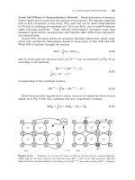
Stefan Condition at an
alp
Interface.
Consider the interface between the moving
Q
and
p
phases shown in Fig.
20.2b.
The
cr
and
,B
phases (along with their V-frames)
will be bodily displaced with respect to each other, and the Stefan condition can
be written as
Figure
20.2:
(b)
Composition profile
produced
by
bonding two thick slabs
of
pure
A
and
pure
B
face
to
face and then annealing
at
TO.
(a)
Phase diagram
for
A-B
binary system.
2Note that the use of a V-frame for diffusion within a phase merely requires that an equation such
as Eq.
3.21
is satisfied. The fact that the volume of the phase may be changing due to the gain
or
loss
of atoms at its interfaces is irrelevant.
506
CHAPTER
20:
GROWTH
OF
PHASES
IN
CONCENTRATION AND
THERMAL
FIELDS
where the relation
v,":
=
[,lye]
"/P
-
v:yP
has been used and where
=
flux of
i
into the
a
phase at the interface measured in
the a-phase V-frame
[Jy']
"lP
=
flux of
i
into the
@
phase at the interface measured in
the @-phase V-frame
t~a";c,
=
velocity
of
the interface measured in the a-phase V-frame
vfll"p
=
velocity of the interface measured in the @-phase V-frame
v,":
=
velocity of the a-phase V-frame measured in the P-phase V-frame
("
=
concentration of
i
at the
a/@
interface on the
@
side
(p
therefore
crP
=
concentration of
i
at the
a/@
interface on the
CY
side
(a
therefore
precedes
a
in the superscript),
precedes
,!3
in the superscript).
b
The two velocities
vLIP
and
v,":
can be determined by solving simultaneously
the two equations given by Eqs. 20.11 for
i
=
(A,
B)
with the help of
Eqs.
3.24, 3.27,
and
A.8.
Taking the interdiffusivities to be constants, independent of concentration,
the results are
[2,
31
The Q and
E
coefficients are given by
1
Q"
=-
0;
A
and the parameter
A
is given by
cP"
"0
"P
Pa
B
'A
-'B
'A
A=
(20.14)
(20.15)
In the special case where
fli
=
02
and
flc
=
RE,,
E"
=
There is then no overall volume change or bodily movement between phases.
=
0
and
Q"
=
QP
=
1.