Mechanical Engineering-Tribology In Machine Design Episode 4 pptx
Bạn đang xem bản rút gọn của tài liệu. Xem và tải ngay bản đầy đủ của tài liệu tại đây (877.57 KB, 25 trang )
62
Tribology in machine design
.fmi,
is recommended. Thus, if
r
=
elc =0.4 and
a'=
123.7", then
so that
and
If p' denotes the load per unit of projected area of the bearing surface and N
is the speed in
r.p.s. then
P
=
2p'r and
V
=
2nrN, so that
and
In using these expressions care must be taken to ensure that the units are
consistent.
Numerical example
A
journal and complete bearing, of nominal diameter 100 mm and length
100 mm, operates with a clearance of c
=0.05 mm. The speed of rotation is
600
r.p.m. and p
=
20 cP. Determine:
(i) the frictional moment when rotating without load;
(ii)
the maximum permissible load and specific pressure (i.e. load per unit
of projected area of bearing surface) knowing that the eccentricity
ratio
elc must not exceed 0.4;
(iii) the frictional moment under load.
The virtual coefficient of friction when
elc =0.4 is l.l(c/r) and the load per
unit length is
(i)
when rotating without load, eqn (2.128) will apply, namely
r2
M
=
2np
V-
per unit length.
I)
Basic principles of tribology
63
To convert from centipoise to (~s)/m~ we have to multiply
,u
=
20
cP
by
10-
3.
Thus
and so
M
=
27r20
x
10-
x
3.1416 x 50
=
19.73
Nm per meter length,
but length of the bearing
=O. 1
m, thus
frictional moment
=
19.73 x 0.1
=
1.973
Nm.
(ii)
load per unit length
and so
maximum permissible load
=
P
x
length of bearing
=478 779.8
x
0.1 =47 877.98
N
478779'8=4.78MPa
specific pressure
=
p'
=- =
2r 0.1
(iii) frictional moment under load,
M=JPr
per unit length, where
fr
=
l.lc
=
1.1 x 0.00005 =0.000055
m
total frictional moment
=
478 779.8
x
0.000055
=
2.63
Nm.
References to Chapter
2
1.
E.
Rabinowicz.
Friction and Wear of Materials.
New York: Wiley, 1965.
2.
J.
Halling (ed.).
Principles
of
Tribology.
Macmillan Education Ltd., 1975.
3.
D.
F.
Moore.
Prirlciples and Applications of Tribology.
Pergamon Press, 1975.
4.
N.
P.
Suh.
Triboph~~sics.
Prentice-Hall, 1986.
5.
F.
P. Bowden and
D.
Tabor.
The Friction and Lubrication of Solids.
Parts
I
&
11.
Oxford: Clarendon Press, 1950, 1964.
6.
I.
V.
Kragelskii,
Friction and Wear.
Washington: Butterworth, 1965.
3.1.
Introduction
3
Elements of contact mechanics
There is a group of machine components whose functioning depends upon
rolling and sliding motion along surfaces while under load. Both surfaces
are usually convex, so that the area through which the load is transferred is
very small, even after some surface deformation, and the pressures and local
stresses are very high. Unless logically designed for the load and life
expected of it, the component may fail by early general wear or by local
fatigue failure. The magnitude of the damage is a function of the materials
and by the intensity of the applied load or pressure, as well as the surface
finish, lubrication and relative motion.
The intensity of the load can be determined from equations which are
functions of the geometry of the surfaces, essentially the radii of curvature,
and the elastic constants of the materials. Large radii and smaller moduli of
elasticity, give larger contact areas and lower pressures. Careful alignment,
smoother surfaces, and higher strength and oil viscosity minimize failures.
In this chapter, presentation and discussion of
contact mechanics
is
confined, for reasons of space, to the most technically important topics.
However, a far more comprehensive treatment of contact problems in a
form suitable for the practising engineer is given in the ESDU tribology
series. The following items are recommended:
ESDU-78035, Contact phenomena
I;
stresses, deflections and contact
dimensions for normally loaded unlubricated elastic
components;
ESDU-84017, Contact phenomena 11; stress fields and failure criteria in
concentrated elastic contacts under combined normal and
tangential loading;
ESDU -85007, Contact phenomena
111; calculation of individual stress
components in concentrated elastic contacts under com-
bined normal and tangential loading.
Although a fairly comprehensive treatment of thermal effects in surface
contacts is given here it is appropriate, however, to mention the ESDU
tribology series where thermal aspects of bearings, treated as a system are
presented, and network theory is employed in an easy to follow step-by-step
procedure. The following items are esentially recommended for the
practising designer
:
ESDU-78026, Equilibrium temperatures in self-contained bearing
assemblies;
Part
I
-
outline of method of estimation;
Elements of contact mechanics
65
ESDU
-78027, Part
I1
-
first approximation to temperature rise;
ESDU
78028, Part
I11
-
estimation of thermal resistance of an assembly;
ESDU-78029, Part
IV
-
heat transfer coefficient and joint conductance.
Throughout this chapter, references are made to the appropriate ESDU
item number, in order to supplement information on contact mechanics
and thermal effects, offer alternative approach or simply to point out the
source of technical data required to carry out certain analysis.
3.2.
Concentrated and
The theory of contact stresses and deformations is one of the more difficult
distributed forces on
topics in the theory of elasticity. The usual approach is to start with forces
plane surfaces
applied to the plane boundaries of semi-infinite bodies, i.e. bodies which
extend indefinitely in all directions on one side of the plane. Theoretically
this means that the stresses which radiate away from the applied forces and
die out rapidly are unaffected by any stresses from reaction forces or
moments elsewhere on the body.
A concentrated force acts at point
0
in case
1
ofTable
3.1.
At any point
Q
there is a resultant stress
q
on a plane perpendicular to 02, directed
through
0
and of magnitude inversely proportional to (r2 +z2), or the
Table
3.1
Loading case Pictorial Stress and deflection
1.
Point
2.
Line
3. Knife edge or pivot
4.
Uniform distributed load
p
over circle of radius
a
5.
Rigid cylinder (El BE2)
L,
1-v2 P
we-p-
at surface
nE r
2
(PI/) cos
8
c=-
-
71
$x2 +z2
0
=-
(P/L)cos
8
r(ct
+
4
sin
2a)
with v=0.3 at point
0
66
Tribology in machine design
Figure
3.1
square of the distance
OQ
from the point of load application. This is an
indication of the rate at which stresses die out. The deflection of the surface
at a radial distance
r
is inversely proportional to
r,
and hence, is a hyperbola
asymptotic to axes
OR
and
OZ.
At the origin, the stresses and deflections
theoretically become infinite, and one must imagine the material near
0
cut
out, say, by a small hemispherical surface to which are applied distributed
forces that are statistically equivalent to the concentrated force P. Such a
surface is obtained by the yielding of the material.
An analogous case is that of concentrated loading along a line of length
1
(case 2). Here, the force is
I?//
per unit length of the line. The result is a
normal stress directed through the origin and inversely proportional to the
first power of distance to the load, not fading out as rapidly. Again, the
stress approaches infinite values near the load. Yielding, followed by
work-
hardening, may limit the damage. Stresses in a knife or wedge, which might
be used to apply the foregoing load, are given under case 3. The solution for
case 2 is obtained when
2% =n, or when the wedge becomes a plane.
In the deflection equation
ofcase 1, we may substitute for the force P, an
expression that is the product of a pressure p, and an elemental area, such as
the shaded area in Fig. 3.1. This gives a deflection at any point,
M,
on the
surface at a distance
r
=s
away from the element, namely
where
t1
is the Poisson ratio. The total deflection at
M
is the superposition
or integration over the loaded area of all the elemental deflections, namely
where
q
is an elastic constant (1
-
v2)/~.
If the pressure is considered
uniform, as from a fluid, and the loaded area is a circle, the resulting
deflections, in terms ofelliptic integrals, are given by two equations, one for
M
outside the circle and one for
M
inside the circle. The deflections at the
centre are given under case
4
of Table 3.1. The stresses are also obtained by
a superposition of elemental stresses for point loading. Shear stress is at a
maximum below the surface.
If a rod in the form of a punch, die or structural column is pressed against
the surface of a relatively soft material,
i.e. one with a modulus of elasticity
much less than that of the rod, the rod may be considered rigid, and the
distribution of deflection is initially known. For a circular section, with
deflection
w
constant over the circle, the results are listed in case 5. The
pressure p is least at the centre, where it is
0.5pa,,, and it is infinite at the
edges. The resultant yielding at the edges is local and has little effect on the
general distribution of pressure. For a given total load, the deflection is
inversely proportional to the radius of the circle.
Elements
of
contact mechanics
67
3.3.
Contact between
When two elastic bodies with convex surfaces, or one convex and one plane
two elastic bodies in the
surface, or one convex and one concave surface, are brought together in
form of spheres
point or line contact and then loaded, local deformation will occur, and the
point or line will enlarge into a surface of contact. In general, its area is
bounded by an ellipse, which becomes a circle when the contacting bodies
are spheres, and a narrow rectangle when they are cylinders with parallel
axes. These cases differ from those ofthe preceding section in that there are
two elastic members. and the pressure between them must be determined
from their geometry and elastic properties.
The solutions for deformation. area of contact, pressure distribution and
stresses at the initial point of contact were made by Hertz. They are
presented in
ESDU
78035
in a form suitable for engineering application.
The maximum compressive stress, acting normal to the surface is equal and
opposite to the maximum pressure, and this is frequently called the Hertz
stress. The assumption is made that the dimensions of the contact area are
small, relative to the radii ofcurvature and to the overall dimensions ofthe
bodies. Thus the radii, though varying, may be taken as constant over the
very small arcs subtending the contact area. Also, the deflection integral
derived for a plane surface. eqn
(3.1),
may be used with very minor error.
This makes the stresses and their distribution the same in both contacting
bodies.
The methods of solution will be illustrated by the case of two spheres of
different material and radii
R,
and
R2.
Figure
3.2
shows the spheres before
and after loading, with the radius
a
of the contact area greatly exaggerated
for clarity. Distance
,-=R-R
cos
7%
R-R(l -y2/2+ )z~y22zr2/2R
because cos
7
may be expanded in series and the small angle
y
z
r/R.
If
points
M1
and
M2
in Fig.
3.2
fall within the contact area, their approach
distance
M1 M2
is
Figure
3.2
I
la1
before
loading
(bl
loaded
where
B
is a constant
(I/2)(1/R1
+
1/R2).
If one surface is concave, as
indicated by the dotted line in Fig.
3.2,
the distance is
zl
-z2
=
(r2/2)(1/~,
-
1/R2)
which indicates that when the contact area is
on the inside of a surface the numerical value of its radius is to be taken as
negative in all equations derived from eqn
(3.1).
68
Tribology in machine design
The approach between two relatively distant and strain-free points, such
as Q and Q2, consists not only of the surface effect
z,
+
z2, but also of the
approach of Q, and Q2 relative to
MI
and M2, respectively, which are the
deformations w, and w2 due to the, as yet, undetermined pressure over the
contact area. The total approach or deflection
6,
with substitution from eqn
(3.1) and (3.2), is
where
=
(1
-
v)
and q2 =(I-
b3;)/E2.
With rearrangement,
'1
J J
For symmetry, the area ofcontact must be bounded by a circle, say of radius
a, and Fig. 3.3 is a special case of Fig. 3.1.
A
trial will show that eqn (3.3) will
be satisfied by a hemispherical pressure distribution over the circular area.
Thus the peak pressure at centre
0
is proportional to the radius a, or
0.0
po
=
ca. Then, the scale for plotting pressure is
c
=po/a. To find
wl
and
w2
at
M
in eqn (3.3), an integration, pds, must first be made along a chord
GH,
which has the half-length
GN
=
(a2
-
r2 sin2
4)*.
The pressure varies as a
semicircle along this chord, and the integral equals the pressure scale
c
Figure
3.3
times the area
A
under the semicircle, or
By
a rotation of line
GH
about
M
from
4
=O
to
4
=
n/2 (half of the contact
circle), the shaded area of Fig. 3.3, is covered. Doubling the integral
completes the integration in eqn (3.3), namely
n
whence
Now the approach
S
of centres
Q,
and
Q2,
is independent of the particular
points
M
and radius
r,
chosen in the representation by which eqn (3.4) was
obtained. To make the equation independent of
r,
the two r2 terms must be
equal, whence it follows that the two constant terms areequal. The r2 terms,
equated and solved for a, yield the radius of the contact area
Elements of contact mechanics
69
The two constant terms when equated give
The integral of the pressure over the contact area is equal to the force
P
by which the spheres are pressed together. This integral is the pressure
Table
3.2
Loading case Pictorial Area, Pressure, Approach
1.
Spheres or sphere and plane
2.
Cylindrical surfaces with parallel
axes
3.
General case
a=0.721[P(ql +q2)DlD2/(Dl
+
~~)]i=c/2
Po
=
1.5P/na2
=
1.5paVg
=
-
(a,),,,
max
r
=ipo,
at depth
0.638a
max
a,
=
(1
-
2v)po/3
at radius
a
I
6: 1.04[(~1 +~Z)~P~(DI+ D2)/D1D21s
po
=
2P/nbl= 1.273~~~~
=
-
(a,),,,
if
v=0.30
max
7
=0.304po
at depth
0.786b
if
~1
=q2
=v
a,
K,
A
are constants and obtained from appropriate diagrams
1
-
v:
1
-
v;
q,
=-
and
q2
=
E
1
E2
70
Tribology in machine design
scale times the volume under the hemispherical pressure plot, or
and the peak pressure has the value
Substitution of eqn
(3.7)
and the value of
B
below eqn
(3.2)
gives to eqns
(3.5)
and
(3.6)
the forms shown for case
1
of Table
3.2.
If both spheres have
the same elastic modulus
El
=
E2
=
E,
and the Poisson ratio is
0.30.
a
simplified set of equations is obtained. With a ball on a plane surface.
R2
=
x,
and with a ball in a concave spherical seat,
R2
is negative.
It has taken all this just to obtain the pressure distribution on the
surfaces. All stresses can now be found by the superposition or integration
of those obtained for a concentrated force acting on a semi-infinite body.
Some results are given under case
1
of' Table
3.2.
An unusual but not
unexpected result is that pressures, stresses and deflections are not linear
functions of load
P,
but rather increase at a less rapid rate than
P.
This is
because of the increase of the contact or supporting area as the load
increases. Pressures, stresses and deflections from several different loads
cannot be superimposed because they are non-linear with load.
3.4.
Contact between
Equations for cylinders with parallel axes may be derived directly, as shown
cylinders and between
for spheres in Section
3.3.
The contact area is a rectangle of width
2b
and
bodies of general shape
length
I.
The derivation starts with the stress for line contact (case
2
ofTable
3.1).
Some results are shown under case
2
of Table
3.2.
Inspection of the
equations for semiwidth b, and peak pressure
po,
indicates that both
increase as the square root of load
P.
The equations of the table, except that
gven for
6,
may be used for a cylinder on a plane by the substitution of
infinity for
R2.
The semiwidth b, for a cylinder on a plane becomes
1.13[(P/l)(q1
+
q2)R
,]
+.
All normal stresses are compressice, with
0,
and
0,
equal at the surface to the contact pressure
po.
Also significant is the
maximum shear stress
err,,
with a value of
0.304~~
at a depth
0.786h.
Case
3
of Table
3.2
pictures a more general case of two bodies, each with
one major and one minor plane of curvature at the initial point of contact.
Axis
Z
is normal to the tangent plane
XY,
and thus the
Z
axis contains the
centres of the radii of curvature. The minimum and maximum radii for
body
1
are
R,
and
R;,
respectively, lying in planes
Y ,Z
and
X ,Z.
For body
2,
they are
R2
and
R;,
lying in planes
Y2Z
and
X2Z,
respectively. The angle
between the planes with the minimum radii or between those with the
maximum radii is
$.
In the case of two crossed cylinders with axes at
90L',
such as a car wheel on a rail,
$
=90G
and
R;
=
R;
=
m.
This general case was
solved by Hertz and the results may be presented in various ways. Here, two
sums
(B
+
A)
and
(B- A).
obtained from the geometry and defined under
case
3
of Table
3.2
are taken as the basic parameters. The area of contact is
an ellipse with a minor axis
2h
and a major axis
2a.
The distribution of
pressure is that of an ellipsoid built upon these axes, and the peak pressure is
Elements of contact mechanics
7
1
3.5. Failures of
contacting surfaces
1.5 times the average value
P/nab.
However, for cylinders with parallel axes,
the results are not usable in this form, and the contact area is a rectangle of
known length, not an ellipse. The principal stresses shown in the table occur
at the centre of the contact area, where they are maximum and compressive.
At the edge of the contact ellipse, the surface stresses in a radial direction
(along lines through the centre of contact) become tensile. Their magnitude
is considerably less than that of the maximum compressive stresses,
e.g.
only 0.133~~ with two spheres and
11
=0.30 by an equation of case 1, Table
3.2, but the tensile stresses may have more significance in the initiation and
propagation of fatigue cracks. The circumferential stress is everywhere
equal to the radial stress, but of opposite sign, so there is a condition of pure
shear. With the two spheres
z
=O.
133p0. Forces applied tangentially to the
surface, such as by friction, have a significant effect upon the nature and
location of the stresses. For example, two of the three compressive principal
stresses immediately behind the tangential force are changed into tensile
stresses. Also, the location of the maximum shear stress moves towards the
surface and may be on it when the coefficient of friction exceeds 0.10.
More information on failure criteria in contacts under combined normal
and tangential loading can be found in ESDU-84017.
There are several kinds of surface failures and they differ in action and
appearance. Indentation (yielding caused by excessive pressure), may
constitute failure in some machine components. Non-rotating but loaded
ball-bearings can be damaged in this way, particularly if vibration and
therefore inertia forces are added to dead weight and static load. This may
occur during shipment of machinery and vehicles on freight cars, or in
devices that must stand in a ready status for infrequent and short-life
operations. The phenomena is called false brinelling, named after the
indentations made in the standard
Brine11 hardness test.
The term,
surface,failure,
is used here to describe a progressive loss of
quality by the surface resulting from shearing and tearing away of particles.
This may be a flat spot, as when a locked wheel slides on a rail. More
generally the deterioration in surface quality is distributed over an entire
active surface because of a combination of sliding and rolling actions, as on
gear teeth. It may occur in the presence of oil or grease, where a lubricating
film is not sufficiently developed, for complete separation of the contacting
surfaces. On dry surfaces, it may consist of a flaking of oxides. If pressures
are moderate, surface failures may not be noticeable until loose particles
develop. The surface may even become polished, with machining and
grinding marks disappearing. The generation of large amounts of particles,
may result from misalignments and unanticipated deflections, on only a
portion of the surface provided to take the entire load. This has been
observed on the teeth of gears mounted on insufficiently rigid shafts,
particularly when the gear is overhung. Rapid deterioration of surface
quality may occur from insufficient lubrication, as on cam shafts, or from
negligence in lubrication and protection from dirt.
A
type of surface failure, particularly characteristic of concentrated
72
Tribology in machine design
(dl
Figure
3.4
contacts, consists of fatigue cracks which progress into and under the
surface, and particles which then fall out of the surface. The holes resulting
from this process are called pits or spalls. This pitting occurs on convex
surfaces, such as gear teeth, rolling element bearings and cams. It is a well-
established fact that the maximum shearing stress occurs below the surfaces
of bodies which are in contact. Hence, at one time, it was strongly held that
the crack forming a pit started at this point of maximum shear stress, then
progressed outwards. Data from pure rolling tests disclosed, however, that
the cracks commonly started at the surface and progressed only in the
presence of oil. A good penetrant, filling any fine cracks present, acted as a
hydraulic wedge. Experiments also revealed that only cracks with their lips
facing the approaching load would progress to failure.
In Fig.
3.4,
a crack,
1,
filled with oil, approaches the loading zone and has
its lip sealed off. As the full length of the crack comes under the load, oil in
the crack cannot escape, and high hydraulic pressure results. After repeated
occurrence of this process, high stress from stress concentration along the
root of the crack to spread by fatigue. Eventually, the crack will progress
towards the surface, favouring the most highly stressed regions. Then, a
particle will fall out, exposing a pit with the typical lines of progressive
cracking, radiating from the pointed lip. The pit may look much as though
it were moulded from a tiny sea shell, with an arrowhead point of origin. Pit
depths may vary from a few microns to about
1
mm, with lengths from two
to four times their depths.
Cracks facing away from the approaching zone of loading, such as crack
2
(Fig.
3.4),
will not develop into pits. The root of the crack first reaches the
loaded area and the oil in the crack is squeezed out by the time its lip is
sealed off. A more viscous oil reduces or eliminates pitting, either by not
penetrating into fine cracks, or by forming an oil film thick enough to
prevent contact between asperities.
There are several possible causes for the initial surface cracks, which only
need to be microscopic or even submacroscopic. Machining and grinding
are known to leave fine surface cracks, either from a tearing action or from
thermal stresses. Polishing inhibits pitting, presumably by the removal of
these cracks. Along the edges of spherical and elliptical contact areas a
small tensile stress is present under static and pure-rolling conditions.
Tangential forces caused by sliding combined with rolling, as on gear teeth,
add tensile stresses to the above and to the rectangular contact area of
cylinders. Surface inclusions at the tensile areas create stress concentrations
and add to the chance that the repeated tensile stresses will initiate cracks.
Sometimes a piece that has dropped out of a pit passes through the contact
zone, making a shallow indentation probably with edge cracks. Sometimes
the breaking out of material continues rapidly in a direction away from the
arrowhead point of origin, increasing in width and length. It is then called
spalling. Spalling occurs more often in rolling-element bearings than in
gears, sometimes covering more than half the width of a bearing race.
Propagation of the crack from the surface is called a point-surface origin
mode of failure. There might be so-called inclusion-origin failure. Inclu-
Elements of contact mechanics
73
sions are non-metallic particles that are formed in, and not eliminated from,
the melt in the refining process. They may be formed during the
deoxidization of steel or by a reaction with the refractory of the container.
The inclusion does not bond with the metal, so that essentially a cavity is
present with a concentration of stress. The usual way to detect inclusions is
by a magnetic particle method. A crack, starting at the inclusion, may
propagate through the subsurface region for some distance, or the crack
may head for the surface. If cracks on the surface form, further propagation
may be by hydraulic action, with a final appearance similar to that from a
point-surface origin. The damaged area is often large. It is well known that
bearings made from vacuum-melted steel, and therefore a cleaner, more
oxide-free steel, are less likely to fail and may be given higher load ratings.
There are three other types of failure which usually occur in heavily
loaded roller bearings in test rigs. Geometric stress concentration occurs at
the ends of a rectangular contact area, where the material is weaker without
side support. Slight misalignment, shaft slope or taper error will move much
of the load to one of the ends. In peeling, fatigue cracks propagate over large
areas but at depths of 0.005 to 0.01 mm. This has been attributed to loss of
hydrodynamic oil film, particularly when the surface finish has many
asperities which are greater than the film thickness under the conditions of
service.
Subcase fatigue occurs on carburized elements where the loads are
heavy, the core is weak and the case is thin, relative to the radii of curvature
in contact. Cracks initiate and propagate below the effective case depth, and
cracks break through to the surface at several places, probably from a
crushing of the case due to lack of support.
3.6.
Design values and
Previous investigations, some of which are published, have not produced a
procedures
common basis on which materials, properties, component configuration,
operating conditions and theory may be combined to determine dimen-
sions for a satisfactory life of concentrated contacts. The investigations
indicate that much progress is being made, and they do furnish a guide to
conditions and changes for improvement. Most surface-contact com-
ponents operate satisfactorily, and their selection is often based on a
nominal Hertz pressure determined from experience with a particular
component and material, or a selection is made from the manufacturers
tables based on tests and experience with their components. The various
types of stresses, failures and their postulated causes, including those of
subsurface origin, are all closely related to the maximum contact pressure
calculated by the Hertz equations. If an allowable maximum Hertz pressure
seems large compared with other physical properties of the particular
material, it is because it is a compressive stress and the other two principal
stresses are compressive. The shear stresses and tensile stresses that may
initiate failures are much smaller. Also, the materials used are often
hardened for maximum strength. Suggestions for changes in contact-stress
components by which their load or life may be increased are:
1. larger radii or material of a lower modulus of elasticity to give larger
contact area and lower stress;
74
Tribology in machine design
2.
provision for careful alignment or minimum slope by deflection of
parallel surfaces, or the provision of crowned surfaces as has been done
for gear teeth, bearing rollers and cam followers;
3.
cleaner steels, with fewer entrapped oxides (as by vacuum melting);
4.
material and treatments to give higher hardness and strength at and
near the surface, and if carburized, a sufficient case depth (at least
somewhat greater than the depth to maximum shear stress) and a strong
core;
5.
smoother surfaces, free of fine cracks, by polishing, by careful running-in
or by avoidance of coarse machining and grinding and of nicks in
handling;
6.
oil of higher viscosity and lower corrosiveness, free of moisture and in
sufficient supply at the contacting surfaces. No lubricant on some
surfaces with pure rolling and low velocity;
7.
provision for increased film thickness of asperity-height ratio, the so-
called lambda ratio
(IL>
1.5).
3.7.
Thermal effects in
The surface temperature generated in contact areas has a major influence
surface contacts
on wear, scuffing, material properties and material degradation. The
friction process converts mechanical energy primarily into thermal energy
which results in a temperature rise. In concentrated contacts, which may be
separated by a full elastohydrodynamic film, thin-film boundary lubricated
contacts, or essentially unlubricated contacts, the friction intensity may be
sufficiently large to cause a substantial temperature rise on the surface. The
methods to estimate surface temperature rise presented in this section are
all based on simplifying assumptions but nevertheless can be used in design
processes. Although the temperature predicted may not be precise, it will
gve an indication of the level of temperature to expect and thereby give the
designer some confidence that it can be ignored, or it will alert the designer
to possible difficulties that may be encountered because of excessive
temperatures.
The most significant assumption, involved in calculating a surface
temperature, is the actual or anticipated coefficient of friction between the
two surfaces where the temperature rise is sought. The coefficient of friction
will depend on the nature of the surface and can vary widely depending on
whether the surfaces are
drylunlubricated or
if
they are lubricated by
boundary lubricants, solids, greases, hydrodynamic or elastohydrody-
namic films. The coefficient of friction enters to the first power and is, in
general, relatively unpredictable. If measurements of the coefficient of
friction are available for the system under consideration, they frequently
show substantial fluctuations. Another assumption is that all the energy is
conducted into the solids in contact, which are assumed to be at a bulk
temperature some distance away from the contact area. However, the
presence of a lubricant in the immediate vicinity of the contact results in
convection heat transfer, thereby cooling the surfaces close to the contact.
This would generally tend to lower the predicted temperature.
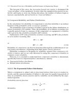
The calculations focus on the flash temperature. That is the temperature
Elements of contact mechanics
75
rise in the contact area above the bulk temperature of the solid as a result of
friction energy dissipation. However, the temperature level, not rise, in the
contact area is frequently of major concern in predicting problems
associated with excessive local temperatures. The surface temperature rise
can influence local surface geometry through thermal expansion, causing
high spots on the surface which concentrate the load and lead to severe local
wear.
The temperature level, however, can lead to physical and chemical
changes in the surface layers as well as the surface of the solid. These
changes can lead to transitions in lubrication mechanisms and wear
phenomena resulting in significant changes in the wear rate. Therefore, an
overall system-heat transfer analysis may be required to predict the local
bulk temperature and therefore the local surface temperature. Procedures
are available for modelling the system-heat transfer problems by network
theory and numerical analysis using commercially available finite element
modelling systems.
ESDU
items 78026 to 78029 are especially recom-
mended in this respect.
There is considerable literature on the subject of surface temperatures,
covering both general aspects and specific special situations, but compared
to theoretical analysis, little experimental work has been reported.
3.7.1.
Analysis of line contacts
Blok proposed a theory for line contacts which will be summarized here.
The maximum conjunction temperature,
Tc, resulting from frictional
heating between counterformal surfaces in a line contact is
where
T,, the bulk temperature, is representative of the fairly uniform level
of the part at some distance from the conjunction zone.
Tf represents the
maximum flash temperature in the conjunction zone resulting from
frictional heating.
Tf may be calculated from the following formula:
where
fis the instantaneous coefficient of friction,
w
is the instantaneous
width of the band shaped conjunction, m,
W
is the instantaneous load on
the conjunction,
N,
L
is the instantaneous length of the conjunction
perpendicular to motion, m,
V,,
V2
are the instantaneous velocities of
surfaces
1
and 2 tangential to the conjunctionzone and perpendicular to the
conjunction band length,
m/s, b,,
b2
are the thermal contact coefficients of
bodies
1
and 2 and
where
ki, pi, ci and aTi are the thermal conductivity, density, specific heat per
unit mass and thermal diffusivity of solid i, respectively.
76
Tribology in machine design
If both bodies are of the same material, the maximum flash temperature
can be written in one of the following three forms in commonly available
variables
:
In addition to the previously defined variables we have
b
=
~pkc
-
thermal contact coefficient
-
[rn2
+
]
E=E1/(1 -v:)
El,
v1
=modulus of elasticity and Poisson's ratio of the solid
the equivalent radius of undeformed
surfaces,
m,
p,
=
Hertzian (maximum) pressure in the contact, N/m2
The numerical factors, 1.11, 0.62 and 2.45 are valid for a semi-elliptical
(Hertzian) distribution of the frictional heat over the contact width, w. This
would be expected from a Hertzian contact with a constant coefficient of
friction, or an elastohydrodynamic contact for a lubricant with a limiting
shear stress proportional to pressure. Obviously, a consistent set of units
must be chosen to give
Tf
in units of degrees centigrade.
The Blok flash temperature formulas apply only to cases for which the
surface Peclet numbers, L, are sufficiently high. This is generally true for
gear contacts which were the focus of
Blok's experiments.
The Peclet number, or dimensionless speed criterion, is defined as
where the variables involved are defined above. An interpretation of the
Peclet number can be given in terms of the heat penetration into the bulk of
the material.
We now consider the instantaneous generation
ofenergy at the surface of
body
i
at a time zero. At a depth of half the contact width, w/2: below the
surface, the maximum effect of this heat generation occurs after a time
tl,
where
Elements of contact mechanics
77
The time for the point on the surface to move through half the contact
width,
~/2, is
and therefore the Peclet number, eqn (3.9e), can be written as
Hence the Peclet number (or dimensionless speed parameter) can be
interpreted as the ratio of the time required for the friction heat to penetrate
the surface a distance equal to half the contact width, divided by the time in
which a point on the surface travels the same distance.
Equations
(3.9a) to (3.9d) assume that both surfaces are moving and that
the Peclet number of each surface is at least 5 to 10. The analysis prediction
accuracy will increase as the Peclet number increases beyond these values.
The flash temperature,
T,,
is the maximum temperature rise on the surface
in the contact region above the bulk temperature. For the assumption
underlying the theory and given above, the maximum temperature will be
located at about
where
X
is measured from the contact edge at which the material enters the
contact region.
The analysis presented above can be illustrated by the following
numerical example. Consider two steel (1 per cent chrome) cylinders each
100 mm diameter and 30 mm long rotating at different speeds such that the
surface velocities at the conjunction are
V,
=
3.0 m s-
'
and V2
=
1.0 m s-
'.
The contact load is lo5 N or 3.33
x
lo6 N/m and the bulk temperature of
each roller is 100
OC.
The thermal properties ofthe material (see Table 3.3 or ESDU-84041 for
a more comprehensive list of data) are
k
=
55 W/m "C
(at 100 "C),
p
=
7865 kg/m3,
c,
=
0.46 kJ/kg "C,
therefore
The Young modulus
El
=
2.068
x
10'
'
N/m2 and
v1
=0.30, thus
Table
3.3.
Typical thermal properties of some solids
Properties at
20
"C Thermal conductivity, k[W/m "C]
Material
-
Aluminium (pure)
Steel
(C,,,
=
0.5
%)
Tungsten steel
Copper
Aluminium bronze
Bronze
Silicon nitride
Titanium carbide
Graphite
Nylon
Polymide
PTFE
Silicon oxide (glass)
Elements of contact mechanics
79
E
=
2.27
x
10'' N/m2. The equivalent radius of contact is
Contact width, based on Hertz theory
=
1.94
x
10-
m
=
1.94 mm.
Hertzian stress
pH
=
2.19 GPa.
Checking the Peclet number for each surface we get
We find that both Peclet numbers are greater than 10. Thus, using eqn
(3.9a)
and with equal bulk temperatures of 100°C the maximum surface
temperature is
T, =435
+
100
=
535
"C.
3.7.2.
Refinement for unequal bulk temperatures
It has been assumed that the bulk temperature, Tb, is the same for both
surfaces. If the two bodies have different bulk temperatures,
Tbl and Tb2,
the Tb in eqn (3.8) should be replaced with
where
If
0.2
6
n
6
5, to a good approximation,
80
Tribology in machine design
3.7.3.
Refinement for thermal bulging in the conjunction zone
Thermal bulging relates to the fact that friction heating can cause both
thermal stresses and thermoelastic strains in the conjunction region. The
thermoelastic strains may result in local surface bulging, which may shift
and concentrate the load onto a smaller region, thereby causing higher flash
temperatures.
A
dimensionless thermal bulging parameter, K, has the form
where all the variables are as defined above except,
r
is the coefficient of
linear thermal expansion
(11°C). Note: pH is the maximum Hertz pressure
that would occur under conditions of elastic contact in the absence of
thermal bulging. In other words, it can be calculated using Hertz theory. In
general, for most applications
and for this range there is a good approximation to the relation between the
maximum conjunction pressure resulting from thermal
bulgng, p,, and the
maximum pressure in the absence of thermal bulging,
pH, namely
and the ratio of the contact widths
wk and WH, respectively, is
which, when substituted into the flash temperature expressions, eqn
(3.9a),
results simply in a correction factor multiplying the original flash
temperature relation
where the second subscript, k, refers to the flash temperature value
corrected for the thermal bulge phenomena.
The thermal bulging phenomena can lead to a thermoelastic instability in
which the bulge wears, relieving the local stress concentration, which then
shifts the load to another location where further wear occurs.
3.7.4. The effect of surface layers and lubricant
film
The thermal effects of surface layers on surface temperature increase may be
important if they are thick and of low thermal conductivity relative to the
bulk solid. If the thermal conductivity of the layer is low, it will raise the
surface temperature, but to have a significant influence, it must be thick
compared to molecular dimensions. Another effect of excessive surface
temperature will be the desorption of the boundary lubricating film leading
to direct metal-metal contacts which in turn could lead to a further increase
Elements of contact mechanics
8
1
of temperature. Assuming the same frictional energy dissipation, at low
sliding speeds, the surface temperature is unchanged by the presence of the
film. At high sliding speeds, the layer influence is determined by its thickness
relative to the depth of heat penetration,
x,,
where
u-r
=thermal diffusivity of the solid, (m2 s-
')
and
t
=
w/V
=
time of heat
application,
(sec).
For practical speeds on materials and surface films, essentially all the
heat penetrates to the substrate and its temperature is almost the same as
without the film. Thus, the thermal effect of the film is to raise the surface
temperature and to lower or leave unchanged the temperature of the
substrate. The substrate temperature will not be increased by the presence
of the film unless the film increases the friction. A more likely mechanism by
which the surface film will influence the surface temperature increase, is
through the influence the film will have on the coefficient of friction, which
results in a change in the amount of energy being dissipated to raise the
surface temperature. The case of a thin elastohydrodynamic lubricant film
is more complicated because it is both a low thermal conductivity film and
may be thick enough to have substantial temperature gradients. It is
possible to treat this problem by assuming that the frictional energy
dissipation occurs at the
midplane of the film, and the energy division
between the two solids depends on their thermal properties and the film
thickness. This results in the two surfaces having different temperatures as
long as they are separated by a film. As the film thickness approaches zero
the two surface temperatures approach each other and are equal when the
separation no longer exists.
For the same kinematics, materials and frictional energy dissipation, the
presence of the film will lower the surface temperatures, but cause the film
middle region to have a temperature higher than the unseparated surface
temperatures. The case of a thin elastohydrodynamic film can be modelled
using the notion of a slip plane. Assuming that in the central region of the
film there is only one slip plane, y
=
hl
(see Fig. 3.5), the heat generated in
this plane will be dissipated through the film to the substrates.
Because the thickness of the film is much less than the width of the
contact, it can therefore, be assumed that the temperature gradient along
the x-axis is small in comparison with that along the y-axis. It is further
assumed that the heat is dissipated in the y direction only.
Friction-
generated heat per unit area of the slip plane is
__C
Qo
=
7,
v, (3.16)
where
zs
is the shear stress in the film and V is the relative sliding velocity. If
-
all the friction work is converted into heat, then
vz
Figure
3.5
82
Tribology in machine design
The ratio of Q, and Q2 is
Equation (3.17) gives the relationship between the heat dissipated to the
substrates and the location of the slip plane. Temperatures of the substrates
will increase as a result of heat generated in the slip plane. Thus, the increase
in temperature is given by
where Q(t
-
c) is the flow of heat during the time
(t
-
c),
ki
is the thermal
conductivity,
ci
is the specific heat per unit mass and
pi
is the density.
3.7.5.
Critical temperature for lubricated contacts
The temperature rise in the contact zone due to frictional heating can be
estimated from the following formula, proposed by
Bowden and Tabor
where
J
is the mechanical equivalent of heat and
g
is the gravitational
constant. The use of the fractional film defect is the simplest technique for
estimating the characteristic lubricant temperature,
T,, without getting
deeply involved in surface chemistry.
The fractional film defect is given by eqn (2.67) and has the following
form
30.9
x
10~~m*]
(
Ec
)I
~=l-~~p{-[
VM+
exp
RTc
.
If a closer look is taken at the fractional film defect equation, as affected by
the heat of adsorption of the lubricant,
E,, and the surface contact
temperature,
T,, it can be seen that the fractional film defect is a measure of
the probability of two bare asperital areas coming into contact. It would be
far more precise if, for a given heat of adsorption for the lubricant-substrate
combination, we could calculate the critical temperature just before
encountering
p
>
0.
In physical chemistry, it is the usual practice to use the points, T,
,
and
Tc2, shown in Fig. 3.6, at the inflection point in the curves. However, even a
small probability of bare asperital areas in contact can initiate rather large
regenerative heat effects, thus raising the flash temperature
Tf. This
substantially increases the desorption rate at the exit from the conjunction
zone so that almost immediately
p
is much larger at the entrance to the
-
conjunction zone. It is seen from Fig. 3.6 that when T, is increased, for a
Tc
given value E,,
p
is also substantially increased. It is proposed therefore,
Figure
3.6
that the critical point on the p-curve will be where the change in curvature
Elements of contact mechanics
83
Figure
3.7
first becomes a maximum. Mathematically, this is where d2P/dT: is the first
maximum value or the minimum value of
p, where d3p/d~: =O. Thus,
starting with eqn (2.67) it is possible to derive the following expression
for
T,
Equation (3.20) is implicit and must be solved by using a microcomputer,
for instance, in order to obtain values for T,.
3.7.6. The case of circular contact
Archard has presented a simple formulation for the mean flash temperature
in a circular area of real contact of diameter 2a. The friction energy is
assumed to be uniformly distributed over the contact as shown schemati-
cally in Fig. 3.7. Body 1 is assumed stationary, relative to the conjunction
area and body 2 moves relative to it at a velocity
V.
Body 1, therefore,
receives heat from a stationary source and body
2
from a moving heat
source. If both surfaces move (as with gear teeth for instance), relative to the
conjunction region, the theory for the moving heat source is applied to both
bodies.
Archard's simplified formulation also assumes that the contacting
portion of the surface has a height approximately equal to its radius, a, at
the contact area and that the bulk temperature of the body is the
temperature at the distance, a, from the surface. In other words, the
contacting area is at the end of a cylinder with a length-to-diameter ratio of
approximately one-half, where one end of the cylinder is the rubbing surface
and the other is maintained at the bulk temperature of the body. Hence the
model will cease to be valid, or should be modified, as the length-to-
diameter ratio of the slider deviates substantially from one-half, and/or as
the temperature at the root of the slider increases above the bulk
temperature of the system as the result of frictional heating. If these
assumptions are kept in mind, Archard's simplified formulation can be of
value in estimating surface flash temperature, or as a guide to calculations
with modified contact geometries.
For the stationary heat source, body 1, the mean temperature increase
above the bulk solid temperature is
where
Q1 is the rate of frictional heat supplied to body 1, (Nm s- I), k1 is the
thermal conductivity of body 1,
(W/m
"C)
and a is the radius of the circular
contact area, (m).
If body
2
is moving very slowly, it can also be treated as essentially a
84
Tribology in machine design
stationary heat source case. Therefore
Figure
3.8
where
Q2
is the rate of frictional heat supplied to body 2 and
k2
is the
thermal conductivity of body 2.
The speed criterion used for the analysis is the dimensionless parameter,
L, called the Peclet number, given by eqn
(3.9e). For L <0.1, eqn (3.22)
applies to the moving surface. For larger values of L
(L> 5) the surface
temperature of the moving surface is
where
x
is the distance from the leading edge of the contact. The average
temperature over the circular contact in this case then becomes
The above expression can be simplified if we define:
Then, for
L<0.1, eqns (3.21) and (3.22) become
and for high speed moving surfaces,
(L> 5), eqn (3.24) becomes
and for the transformation region (0.1
6
L6 5)
where it has been shown that the factor
B
is a function of L rangng from
about 0.85 at L
=O.1 to about 0.35 at L =5. Equations (3.25-3.27) can be
plotted as shown in Fig. 3.8.
To apply the results to a practical problem the proportion of frictional
heat supplied to each body must be taken into account.
A
convenient
procedure is to first assume that all the frictional heat available
(Q
=
f
WV)
is transferred to body 1 and calculate its mean temperature rise
(T,,) using
N, and L,. Then do the same for body 2. The true temperature rise
T,
(which must be the same for both contacting surfaces), taking into account
the division of heat between bodies 1 and 2, is given by
To obtain the mean contact surface temperature, T,, the bulk temperature,
Tb, must be added to the temperature rise,
T,.
Elements of contact mechanics
85
Numerical example
Now consider a circular contact 20mm in diameter with one surface
stationary and one moving at
V
=0.5 m s-
'.
The bodies are both of plain
carbon steel
(C
z
0.5%) and at 24
"C
bulk temperature. We recall that the
assumption in the
Archard model implies that the stationary surface is
essentially a cylindrical body ofdiameter 20 mm and length 10 mm with one
end maintained at the bulk temperature of 24
"C.
The coefficient of friction
is 0.1 and the load is
W
=
3000 N (average contact pressure of 10 MPa). The
properties of contacting bodies are (see Table 3.3 or ESDU-84041 for a
more comprehensive list of data)
Therefore
If we assume that all the frictional energy is conducted into the moving
surface
(L,
=
169
>
5), we can then use eqn (3.24)
and if all the frictional energy went into the stationary surface (L,
=O), then
we use eqn (3.21
)
The true temperature rise for the two surfaces is then obtained from eqn
(3.28) and is
3.7.7.
Contacts for which size is determined
by
load
There are special cases where the contact size is determined by either elastic
or plastic contact deformation.
If the contact is plastic, the contact radius, a, is
where
W
is the load and p, is the flow pressure or hardness of the weaker
material in contact.
If the contact is elastic
86
Tribology in machine design
where
R
is the undeformed radius of curvature and
E
denotes the elastic
modulus of a material.
Employing these contact radii in the low and high speed cases discussed
in the previous section gives the following equations for the average
increase in contact temperature
-
plastic deformation, low speed (L
<
0.1)
-
plastic deformation, high speed (L
>
loo),
f
Tm
=:
(npm)'W
3.23
-
elastic deformation, low speed (L
<
0.1
),
-
elastic deformation, high speed (L
>
loo),
3.7.8.
Maximum attainable flash temperature
The maximum average temperature will occur when the maximum load per
unit area occurs, which is when the load is carried by a plastically deformed
contact. Under this condition the N and L variables discussed previously
become
Then at low speeds
(L<O.l), the heat supply is equally divided between
surfaces 1 and 2, and the surface temperatures are
At moderate speeds (0.1
<
L
<
5), less than half the heat is supplied to body
1, and therefore
T,,,
=
0.25QNL, (3.36)
where
Q
ranges from about 0.95 at L =O. 1 to about 0.5 at L
=
5. At very high
speeds
(L> loo), practically all the heat is supplied to body 2, and then
T,,, =0.435~~'. (3.37)
At lower speeds
(5< L< loo), less heat is supplied to body 2 and