Mechanical Engineering-Tribology In Machine Design Episode 7 ppt
Bạn đang xem bản rút gọn của tài liệu. Xem và tải ngay bản đầy đủ của tài liệu tại đây (646.9 KB, 25 trang )
Friction, lubrication and wear in lower kinematic pairs
1
3
7
Again, suppose
x
and
y
are the perpendicular distances of the fulcrum
F
from the lines of action of
T2
and
T,
respectively. It is assumed that the
brake is used in such
a
manner as to prevent the rotation of the drum when
the crane is carrying a load
Q
attached to a rope passing round the
circumference of the barrel. If
a
force
P
at leverage
d
is necessary to support
this load, then
The relation between the effective tensions
T,
and
T2
is given by
where
f
is the coefficient of friction for the contact surfaces and
O
is the angle
of wrap of the band round the drum. Hence, combining the above
expressions
and
so that
To study the effect of varying the ratio
x/y
on the brake action, now
consider the following cases:
Case
1.
x
=O
Here the line of action of
T2
passes through
F
and a downward movement
of the force
P
produces a tightening effect of the band on the drum.
Case
2.
x
=
y
In this case there is no tightening effect since the displacements of
A
and Bin
the directions of
T2
and
T,
are equal in magnitude. Hence, to maintain the
load the band would have to be in a state of initial tension.
Case
3.
x/y
=
eJ
@;
i.e.
P=O
and
x/y=Tl/T2.
For this ratio a small movement of the lever in the negative direction of
P,
1
38
Tribology in machine design
would have the effect of tightening the band, and the brake would be self-
locking.
Case
4.
y =0
Here, the direction of
P
must be reversed to tighten the band on the drum.
From the above conclusions it follows that if er'">x/y
>
1,
downward
movement of the force
P
would tend to slacken the band. Hence for
successful action
x
must be less than
y.
When the brake is used in the manner indicated above there is no relative
sliding between the friction surfaces, so that
f
is the limiting coefficient of
friction for static conditions. The differential tightening effect of the band
brake is used in the design of certain types of friction brake dynamometers.
4.1
1.2.
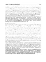
The curved brake block
Figure
4.41
represents a brake block
A
rigidly connected to a lever or
hanger LE pivoted at
E.
The surface of the block is curved to make contact
with the rim of the flywheel
B,
along an arc subtending an angle
214
at the
centre, and is pressed against the rim by a force
P,
at the end
L
of the lever.
In general, the normal pressure intensity between the contact surfaces will
vary along the length of the arc in a manner depending upon the conditions
of wear and the elasticity of the friction lining material of the brake block
surface. Let
p=the intensity of normal pressure at position 0, i.e, p is a
function of
0
and varies from 0=0 to
0=2$,
a
=the radius of the contact surfaces,
b
=the thickness of the brake block,
R=the resultant force on the rim due to the normal pressure
intensity p,
p=the inclination of the line of action of
R
to the position
0
=O.
Figure
4.41
Friction, lubrication and wear in lower kinematic pairs
1
39
Hence, for an element of length ad@ of the arc of contact
normal force
=pub dO,
tangential friction force
=
fpab dO.
The latter elementary force can be replaced by a parallel force of the same
magnitude acting at the centre
0
together with a couple of moment
Proceeding as for the rim clutch and resolving the forces at
0
in directions
parallel and perpendicular to the line of action of R, we have
for the normal force:
parallel to R
pub cos(p
-
O) dO
=
R,
(4.109)
r
2Y
perpendicular to R
J
pub sin(8
-
O) dO
=
0, (4.1 10)
0
for the tangential force:
parallel to R
sin(P- O)dO =O, (4.111)
r
2
Y
perpendicular to R
J
fpab cos(P
-
O) dO
=/K.
(4.1 12)
0
If p is given in terms of 0, the vanishing integral determines the angle
P.
Further, the resultant force at
0
is
and is inclined at an angle
4
=tan-
'
f
to the direction of R. Again, the
couple
M
together with force R at
0
can be replaced by a parallel force R1
acting at a perpendicular distance
h
from
0
given by
The circle with centre
0
and radius
h
is the friction circle for the contact
surfaces, and the resultant force on the wheel rim is tangential to this circle.
In the case of symmetrical pressure distribution,
P=
I),
and the line of
action of R bisects the angle subtended by the arc ofcontact at the centre
0.
The angle O is then more conveniently measured from the line of action of
R, and the above equations become
140
Tribology in machine design
Figure
4A2
Now, it is appropriate to consider the curved brake block in action. Three
cases shall be discussed.
(i)
Unform pressure
Figure 4.42 represents the ideal case in which the block is pivoted at the
point of intersection
C
of the resultant
R,
and the line of symmetry. Since
p=$
and the pressure intensity p is constant, eqns
(4.1 15)
and
(4.116)
apply, so that
R
=
2pab cos
O
dO
b
=
2pab sin
$
resisting torque
$
M
=2fpa2b$ =flu-
sin
$
and
M
fa
$
h
=
-
R
sec
4
sec
4
sin
$
also
L-2=sin4
sec
4
-
sec
4
so that
$
h=asin4
sin
II/
(ii)
Unvorm wear
Referring to Fig. 4.42, it is assumed that the vertical descent 6 is constant for
all values of
O.
Hence, measuring
O
from the line of symmetry,
normal wear at position
O
=Scos
O
and applying the condition for uniform wear, pa is proportional to Scos
O
or
Applying the integrals as in the preceding case
Friction, lubrication and wear in lower kinematic pairs
141
R=kab($+sin $cos$)
@
M
=
2jka2b cos O dO =2jka2b sin
$
or, resisting torque
and
M
A=
[
2 sin
(I/
Rsecg-asin6 $+sin$cos
$
(iii)
Block pivoted at one extremity
Figure 4.43 shows a brake block or shoe pivoted at or near one extremity of
the arc of contact. For a new well-fitted surface, the pressure distribution
may be approximately uniform. Wear of the friction lining material will,
however, occur more readily at the free end ofthe shoe, since the hinge may
be regarded as being at a constant distance from the centre
0.
Taking the radius through the pivot centre as representing the position
O =0, let 6 =the angular movement of the shoe corresponding to a given
condition of wear.
xz
=movement at position O
=
2a sin +Oh
Hence, pa is proportional to 6a sin O or
Figure 4.43
p=ksinO
In this case, eqns (4.109) to (4.112) will apply, and so
R
=
kab sin
O
cos(P
-
O) dO
PI
Expanding the term cos(Q-
0)
and integrating, this becomes
For the angle
P
we have from eqn (4.110)
tab
lZY
sin O sin(b
-
O)dO -0.
Again, expanding sin@
-
O) and integrating
411,-sin4$
tanP=
1
-
cos 4*
142
Tribology in machine design
Using this value of
/I
the equation for R becomes
R
=
ikab cos /I(l
-
cos 4$)(1+ tan2
/I)
1
-
cos
4$
=
ikab
cos
/I
R
=
f
kab sec
/I
sin2 2$.
For the retarding couple we have
J
2~
=f7ia2b sin O dO
=f7ia2b(1
-
cos
2$)
=
2kfa2b sin2
$
and substituting for
k
in terms of R this reduces to
torque,
M
=@a
cos
/I
sec2
t+b
so that
M
h
=
=
fa
cos
/I
sec2
$
rsec
4
sec
4
In all three cases, as the angle
$
becomes small, the radius of the friction
circle approaches the value
and the torque
This corresponds to the flat block and the wheel rim. In the general case we
may write
M
=
f
'Ra,
where
f'
is the virtual coefficient of friction as already applied to friction in
journal bearings.
Thus
f$
for uniform pressure
f'
=-
sin
$
for uniform wear
f'
=
f2 sin
$
$+sin $cos
$
Friction, lubrication and wear
in
lower kinematic pairs
143
and for zero wear at one extremity
f'
=
f
cos
D
sec2
$.
In every case the retarding couple on the flywheel is
and
so that
Numerical example
A
brake shoe, placed symmetrically in a drum of 305 mm diameter and
pivoted on a fixed fulcrum
E,
has a lining which makes contact with the
drum over an arc as shown in Fig. 4.44. When the shoe is operated by the
force
F,
the normal pressure at position
O
is p =0.53sin
O
MPa. If the
coefficient of friction between the lining and the drum is 0.2 and the width of
the lining is 38 mm, find the braking torque required. If the resultant
R
of
the normal pressure intensity
p
is inclined at an angle to the position
O
=
0, discuss with the aid ofdiagrams the equilibrium of the shoe when the
direction of rotation is (a) clockwise and (b) anticlockwise.
Solution
Applying eqn (4.127), the braking torque is given by
M
fpa2b dO
S
5
n/6
=fio2b
Ll4
sin
0
de
=&a2b[cos
in
-
cos
in],
,
where f=0.2,
k
=0.53 MPa,
a
=
1525 mm and
b
=
38 mm. Thus
II
M
=0.2
x
0.53
x
0.15252
x
0.038
M
=
146.3 Nm.
F
Since
R
is the resultant of the normal pressure intensity, p, the angle
P
is
[pabsin(fl-0)dO=O
Figure
4.44
J
144
Tribology in machine design
i.e.
sin @sin(P-@)d@=O.
Expanding sin(P
-
@)
and integrating, this equation becomes
Hence
~5~16
and proceeding as follows
5
n/6
R
=
ikab[-
cos Pcos 20 +sin P(20
-
sin 20)]
=$kab[-ices
P+
5.531 sin
PI,
where
p
=
95.2".
Substituting the numerical values
For the radius of the friction circle
M
h=-
-
146.3
=
0.034 m.
R sec
$
-
4264- 1.02
Alternatively,
so that
In Fig. 4.44,
R1
=
R sec
6
is the resultant force opposing the motion of the
drum.
R;, equal and opposite to R ,, is the resultant force on the shoe. The
reaction
Q
at the hinge passes through the point of intersection of the lines
of action of
R;
and
F.
As the direction of
Q
is known, the triangle of forces
representing the equilibrium of the shoe can now be drawn. The results are
as follows:
(a) clockwise rotation,
F
=
1507
N;
(b) anticlockwise rotation,
F
=
2710
N.
4.1
1.3.
The band and block brake
Figure 4.45 shows a type of brake incorporating the features of both the
simple band brake and the curved block. Here, the band is lined with a
Friction, lubrication and wear in lower kinematic pairs
145
z
number of wooden blocks or other friction material, each of which is in
T2
contact with the rim of the brake wheel. Each block, as seen in the elevation,
subtends an angle
2$
at the centre of the wheel. When the brake is in action
the greatest and least tensions in the brake strap are
TI
and
T2,
respectively,
Y,
,-
x
and the blocks are numbered from the point of least tension,
T2.
[#-PI
Let
kT2
denote the band tension between blocks 1 and
2.
The resultant
force
R',
exerted by the rim on the block must pass through the point of
intersection of
T2
and
kT2.
Again, since
2$
is small, the line of action of
R;
will cut the resultant normal reaction
R
at the point
C
closely adjacent to
1,
the rim, so that the angle between
R
and
R;
is 4=tan-'f:
Suppose that the angle between
R
and the line of symmetry
OS
is
P,
then,
from the triangle of forces
xyz,
we have
xz
kT2
sin[(:n
-
$)
+
(4
-
P)]
=-
-
-
ZY
T2
sin[(+n
-
$)-
(4
-p)]
=
If this process is repeated for each block in turn, the tension between blocks
2
and
3
is
k.
Hence, if the maximum tension is
T,,
and the number of blocks
is
n,
we can write
Figure
4A5
If the blocks are thin the angle
/?
may
be
regarded as small, so that
COS($
-
4)
1
+tan
$
tan
4
k=
cos($+(b)=l -tan $tan4
k=
+f
tan
*
approximately
1-ftan*
so that
L[
+f
tan
*
]
"
approximately.
T2
'
1-f tan*
4.12.
The role of
The maximum possible acceleration or retardation of a vehicle depends
friction in the propulsion
upon the limiting coefficient of friction between the wheels and the track.
and the braking of
Thus if
-
vehicles
R
=the total normal reaction between the track and the driving
wheels, or between the track and the coupled wheels in the case
of a locomotive,
146
Tribology in machine design
F
=the maximum possible tangential resistance to wheel spin or
skidding, then
Average values off are
0.18
for a locomotive and 0.35 to 0.4 for rubber tyres
on a smooth road surface. Here
f
is called the coefficient of adhesion and
F
is
the traction effort for forward acceleration, or the braking force during
retardation. Both the tractive effort and the braking force are proportional
to the total load on the driving or braking wheels.
During forward motion, wheel spin will occur when the couple on the
driving axle exceeds the couple resisting slipping, neglecting rotational
inertia of the wheels. Conversely, during retardation, skidding will occur
when the braking torque on a wheel exceeds the couple resisting slipping.
The two conditions are treated separately in the following sections.
Case
A.
Tractive effort and driving couple when the rear wheels only
are driven
Consider a car of total mass
M
in which a driving couple
L
is applied to the
rear axle. Let
I,
=the moment of inertia of the rear wheels and axle,
I,
=the moment of inertia of the front wheels,
F1
=the limiting force of friction preventing wheel spin due to the
couple
L,
F2
=the tangential force resisting skidding of the front wheels.
Also, if
b
is the maximum possible acceleration,
a
the corresponding angular
acceleration of the wheels, and
a
their effective radius of action, then
h=aa
(4.141)
Figure
4.46
'I
t
Referring to Fig. 4.46, case (a), the following equations can be written
fortherearwheels
L-Fla=I,a
(4.142)
for the front wheels
F2a
=
12a
for the car
F,
-
F2
=
Mt;
=
Maa
Friction, lubrication and wear in lower kinematic pairs
147
Adding eqns (4.142) and (4.143) and eliminating (F
,-F2) from eqn (4.144),
then
Also, from eqns (4.143) and (4.144)
and eliminating
a
This equation gves the least value of F, if wheel spin is to be avoided. For
example, suppose
M
=
1350 kg,
I
,
=
12.3 kgm2;
I,
=
8.1 kgm2 and
a=0.33m, then
so that, if L exceeds this value, wheel spin will occur.
The maximum forward acceleration
Equation (4.145) gives the forward acceleration in terms of the driving
couple L, which in turn depends upon the limiting friction force
F1 on the
rear wheels. The friction force
F2 on the front wheels will be less than the
limiting value. Thus, if R
,
and R2 are the vertical reactions at the rear and
front axles, then
To determine
R, and R2, suppose that the wheel base is
b
and that the
centre of gravity of the car is x, behind the front axle and y, above ground
level. Since the car is under the action of acceleration forces, motion, for the
system as a whole, must be referred to the centre of gravity
G.
Thus the
forces
F1 and F2 are equivalent to:
(i) equal and parallel forces
F1 and F2 at
G
(Fig. 4.46, case (b)
(ii) couples of moment
Fly and F2y which modify the distribution of the
weight on the springs.
Treating the forces
R1 and R2 in a similar manner, and denoting the weight
of the car by W, we have
148
Tribology in machine design
Equation (4.151) neglects the inertia couples due to the wheels. For greater
accuracy we write
From eqns (4.150) and (4.15 1)
Thus forward acceleration increases the load on the rear wheels and
diminishes the load on the front wheels of the car. Again, since F
=fR1, eqn
(4.153) gives
where
Writing (F
-
F2)
=
M6 and
W
=
Mg, then from eqn (4.155)
maximum forward acceleration, 6
=
fxs
12b
'
(4.156)
b-fy
+=
Case B. Braking conditions
Brakes applied to both rear and front wheels
Proceeding as in the previous paragraph, let
L1 and L2 represent the
braking torques applied to the rear and front axles;
F1 and F2 denote the
tangential resistance to skidding. Referring to Fig. 4.47,
tj
is the maximum
possible retardation and a the corresponding angular retardation of the
wheels, so that, if skidding does not occur, we have:
fortherearwheels
L1-Fla=Ilor (4.157)
for the front wheels
L2
-
F2a
=
12a
for the car F1+F2=Mtj=Maa
.
(L1+L2)a
V=
I,+I~+M~~'
where
Figure
4.47
Friction, lubrication and wear in lower kinematic pairs
149
Using the same numerical data given in the previous section
or
L1
+
L2
=
1.
144(F1
+
F2)a.
If
(L1
+
L2)
exceeds this value, skidding will occur.
The maximum retardation
Suppose that limiting friction is reached simultaneously on all the wheels,
so that
F1 =fR1
and
F2 =fR2 (4.163)
then, referring all the forces, for the system as a whole, to the centre of
gravity,
G
or, more accurately, in accordance with eqn
(4.152)
(F1 +F~)Y=R~x-R~(~-x)-(I~
+I~)oL,
so that,
Rl =CWx-(F, +F2)~~l/b,
R2
=
[
W(b
-
X)
+
(F
1
+
F,)y]/b.
Hence from eqns
(4.163)
and
(4.164)
and
maximum retardation
=
fg.
(4.170)
Under running conditions the braking torques on the front and rear axles
may be removed in a relatively short time interval, during which the
retardation remains sensibly constant. As
L2
is reduced,
F2
diminishes also
and passes through a zero value when
L2
=
12a.
For smaller values of
L2
it
becomes negative; when
L2
=O
the angular retardation of the wheels is due
entirely to the tangential friction force.
If, through varying conditions of limiting friction at either of the front
wheels, or because of uneven wear in the brake linings, the braking torques
on the two wheels are not released simultaneously,
a
couple tending to
150
Tribology in machine design
4.13.
Tractive
resistance
rotate the front axle about a vertical axis will be instantaneously produced,
resulting in unsteady steering action. This explains the importance of equal
distribution of braking torque between the two wheels of a pair.
Brakes applied to rear wheels only
When
L2
=
0, eqns (4.157)-(4.159) become
I2a
F1 =Mu= Maa,
a
from which
maximum retardation
=
zj
=
Lla (4.171)
1,+12+
Ma2'
These results correspond with eqns (4.145) and (4.146) for driving
conditions.
The maximum retardation
In this case limiting friction is reached on the rear wheels only, so that
F,
=fR
and, applying eqn (4.168),
where
Again, writing
W
=
Mg, eqn (4.164) may be written as
Fl+F2=MG
and, eliminating F and F, from eqn (4.173)
maximum retardation
=
G
=
fx
12b
b+fy+-
Ma2
In the foregoing treatment of driving and braking, the effects of friction in
the bearings were neglected. However, friction in the wheel bearings and in
the transmission gearing directly connected to the driving wheels is always
present and acts as a braking torque. Therefore, for a vehicle running freely
on a level road with the power cut off, the retardation is given by eqn
(4.160), where L1 and L2 may be regarded as the friction torques at the rear
Friction, lubrication and wear in lower kinematic pairs
15
1
4.14.
Pneumatic
tyres
Figure
4.48
la)
I
bl
Figure
4.49
and front axle bearings. When running at a constant speed these friction
torques will exert a constant tractive resistance as given by eqns
(4.157)
and
(4.158)
when
a
=0,
i.e.
F,
+
F,
=
(L,
+
L2)/a.
This tractive resistance must be
deducted from the tractive effort to obtain the effective force for the
calculation of acceleration. It must be remembered that there is no loss of
energy in a pure rolling action, provided that wheel spin or skidding does
not occur. In the ideal case, when friction in a bearing is neglected, so that
L,
=
L,
=O
and
F, =F2 =0,
the vehicle would run freely without
retardation.
A pneumatic tyre fitted on the wheel can be modelled as an elastic body in
rolling contact with the ground. As such, it is subjected to creep and micro-
slip. Tangential force and twisting arising from the lateral creep and usually
referred to as the cornering force and the self-aligning torque, play, in fact, a
significant role in the steering process of a vehicle. For obvious reasons, the
analysis which is possible for solid isotropic bodies cannot be done in the
case of a tyre. Simple, one-dimensional models, however, have been
proposed to describe the experimentally observed behaviour. An ap-
proximately elliptically shaped contact area is created when a toroidal
membrane with internal pressure is pressed against a rigid plane surface.
The size of the contact area can be compared with that created by the
intersection ofthe plane with the undeformed surface ofthe toroid, at such a
location as to give an area which is sufficient to support the applied load by
the pressure inside the toroid. The apparent dimensions of the contact
ellipse
x
and
y
(see Fig.
4.48)
are a function of the vertical deflection of the
tyre
x=[(~R-6)6It
and
y=[(b-6)6If. (4.175)
The apparent contact area is
It is known, however, that the tyre is tangential to the flat surface at the edge
of the contact area and therefore the true area is only about
80
per cent of
the apparent area given by eqn
(4.176).
It has been found that ap-
proximately
80
to
90
per cent of the external load is supported by the
inflation pressure. On the other hand, an automobile tyre having a stiff
tread on its surface forms an almost rectangular contact zone when forced
into contact with the road. The external load is transmitted through the
walls to the rim. Figure
4.49
shows, schematically, both unloaded and
loaded automobile tyres in contact with the road. As a result of action ofthe
external load,
W,
the tension in the walls decreases and as a consequence of
that the curvature of the walls increases. An effective upthrust on the hub is
created in this way. In the ideal case of a membrane model the contact
pressure is uniformly distributed within the contact zone and is equal to the
pressure inside the membrane. The real tyre case is different because the
contact pressure tends to be concentrated in the centre of the contact zone.
This is mainly due to the tread.
152
Tribology in machine design
4.14.1. Creep of an automobile tyre
An automobile tyre will tend to creep longitudinally if the circumferential
strain in the contact patch is different from that in the unloaded periphery.
In accordance with the theory oft he membrane, there is a shortening in the
contact patch of the centre-line of the running surface. This is equal to the
difference between the chord
AB
and the arc
AB
(see Fig. 4.48). This leads to
a strain and consequently to a creep given here as a creep ratio:
The silent assumption regarding eqn (4.177) is that the behaviour of the
contact is controlled by the centre-line strain and that there is no strain
outside the contact. The real situation, however, is different.
4.14.2. Transverse tangential forces
Transverse frictional forces and moments are operating when the plane of
the tyre is slightly skewed to the plane of the road. This is usually called
sideslip. Similar conditions arise in the response to spin when turning a
corner. The usual approach to these problems is the same as that for solid
bodies. The analysis starts with the contact being divided into a stick region
at the front edge of the contact patch and a slip region at the rear edge. The
slip region tends to spread forward with the increase in sideslip or spin.
Figure 4.50 shows one-dimensional motion describing the resistance of the
tyre to
lateral displacement. This displacement, k, of the equatorial line of
the tyre results in its lateral deformation. The displacement, k is divided into
displacement of the carcass,
kc, and the displacement of tread, kt. The
carcass is assumed to carry a uniform tension
R
resulting from the internal
pressure. This tension acts against lateral deflection. The lateral deflection
is also constrained by the walls acting as a spring of stiffness
G
per unit
length. The tread also acts as an elastic foundation. Surface traction,
g(x),
acting in the region
-
c
<
x
<
c
deforms the tyre. The equilibrium equation
is of the form
Figure
4.50
+(I
Friction, lubrication and wear in lower kinematic pairs
153
Figure
4.51
where G, is called the tread stiffness. The velocity of lateral slip in the
contact zone (rigid ground,
k,=O
and onedimensional motion) is de-
scribed by
It should also be remembered that in a stick regime,
3
=O.
It seems that the
propositions to assume a rigid carcass and allow only for the deformation of
the tread are not realistic. A more practical model is to neglect the tread
deflection and only consider carcass deformation, i.e.
k=
kc. With this
assumption, eqn (4.178) becomes
where
y
=
(R/Gc)+is the relaxation length. Assuming further that
S
=O
in the
entire contact zone, the displacement within the contact zone for a case of
slideslip is given by
where
k
is the displacement at the entry to the contact zone. Outside the
contact zone g(x)=O, therefore eqn (4.180) yields
in front of the contact
k=k,
expC(c+x)/yI;
at the rear of the contact
k
=
k,
exp[(c
-
x)/y].
At the leading edge, the displacement gradient is continuous and therefore
k
=
-
yrc.
Figure 4.5 1 shows the equatorial line in a deflected state. In the
contact zone
gl(x)
=
G,
k
=
-
G,K(~
+
c
+
x)
(4.184)
which corresponds to a force
Q'
=
-2Gcc(y -kc).
At the rear of the contact zone, there is a discontinuity in dk/dx which
gives rise to an infinite traction q"(c) corresponding to a force
1
54
Tribology in machine design
Q"
=
-
2G,~y(y
+
c). The total cornering force is thus
Self-aligning torque can be found by taking moments about
0
The infinite traction at the rear of the contact zone produces slip, so that the
deformed shape
k(x) has no discontinuity in gradient and conforms to the
condition
g(x) =fp(x) within the slip region.
4.14.3.
Functions of the tyre in vehicle application
The most widely known application of pneumatic tyres is the vehicle
application. In this application the pneumatic tyre fulfils six basic
functions
:
(i)
allows for the motion of a vehicle with a minimum frictional force;
(ii)
distributes vehicle weight over a substantial area of contact between
the tyre and the road surface;
(iii) secures the vehicle against shock loading;
(iv) participates in the transmission of torque from the engine to the road
surface
;
(v) allows, due to adhesion, for the generation of braking torque, driving
and steering of the vehicle;
(iv) provides stability of the vehicle.
When in a rolling mode the resistance to motion comes from two sources:
-
internal friction resulting from the continuous flexing of tread and walls;
-
external friction due to micro-movement within the contact area between
the wheel and the road.
The tyre, from a design point of view represents a complex problem, the
solution of which requires a compromise. For example, increased ride
comfort means greater shock absorption, but also increased power
consumption in transmitting engine torque.
4.14.4.
Design features of the tyre surface
Another example of a compromise involving the tyre is the incorporation of
a tread pattern into the running band. Under ideal conditions (no rain or
dust deposits on a road surface) the coefficient of sliding friction of about
5
would be attained with a perfectly smooth tread since the adhesion
contribution to friction is maximized by a large available contact area. The
existence of a thin film of water would, in this case, easily suppress the
adhesion and produce very dangerous driving conditions characterized by
a coefficient of friction as low as
0.1
or less. Therefore the tread pattern is
provided on the surface of the tyre to eliminate such a drastic reduction in
the coefficient of friction. However, there is a price to pay, because at the
Friction, lubrication and wear in lower kinematic pairs
155
same time, the coefficient of adhesion component of friction under dry
conditions is seriously reduced to a value less than unity as the area of
contact is reduced by the grooves. Nevertheless, the overall effective
coefficient of friction under wet conditions is considerably increased; a
value off =0.4 for locked wheel skidding on a wet road is typical. The main
0110
role of the grooving on the surface of the tyre is to drain excess water from
zlgzag
r~
bbed
block
the tyre footprint in order to increase the adhesion component of friction.
Thus, an adequate tread pattern offers a compromise between the higher
Figure
4.52
and lower friction coefficients that would be obtained with a smooth tyre
under dry and wet conditions respectively. The usual requirement of the
designer is to ensure that the grooving or channeling in the tread pattern is
capable ofexpelling the water from the tyre footprint during the time which
is available at high rolling speed. Figure 4.52 shows three basic tread
patterns which are used today, called zigzag, ribbed and block.
According to experimental findings the differences in performance of
each type are not very significant. Apart from the basic function of bulk
water removal, the tyre tread must also allow for a localized tread
movement or wiping, to help with the squeezing-out of a thin water film on
the road surface. This can be achieved by providing the tread with spies or
cuts leading into grooves. There are a number of important design features
which a modern tread should have:
(i) channels or grooves. The volume of grooving is almost constant for all
tread types. On average, the grooves are approximately
3
mm wide and
a-fomrn
%\
(ii) lOmm spies or deep; micro-cuts leading into the channels or feeder channels. Their
'\\
&9
///
&>-=-<=/
main function is to allow for tread micro-movement which is
characteristic of the rolling process. Usually, spies do not contribute to
the removal ofwater from the footprint directly. Figure 4.53 shows the
arrangement of channels and spies typical for the zigzag pattern;
A
A
(iii) transverse slots or feeder channels. Their size is less than the main
channels which they serve. The transverse slots are not continuous but
end abruptly within the tread. Their main role is to displace bulk water
from the tyre footprint. They also permit the macro-movement of the
Figure
4.53
tread during the wiping action.
4.14.5.
The mechanism of rolling and sliding
Both rolling and sliding can be experienced by
a
pneumatic tyre. Pure
sliding is rather rare except in case of a locked wheel combined with
flooding due to heavy rainfall. Then, the same tread elements are subjected
to the frictional force and as a result of that, the wear of the tread is uneven
along the tyre circumference. Severe braking but without the wheel being
locked produces wear in a uniform manner along the tyre circumference
since the contact zone is continually being entered by different tread
elements. The extent of wear under such conditions is less, because the mean
velocity of slip of the tread relative to the road surface is much lower.
During the rolling of the tyre, four fundamental elements of the process
156
Tribology in machine design
;T
can be distinguished; free rolling, braking, accelerating, cornering or any
combination ofthem. Figure 4.54 shows the loads acting on the tyre during
(a)
(a) a free rolling, (b) a braked rolling and (c) a driven rolling. In all cases,
h
longitudinal tractive forces are produced in the contact zone, giving rise to
a
net forces Fr, Fb, Fd acting on the tread and the reaction force W acting at a
small distance,
a,
ahead of the contact centre. In the case of free rolling there
L@
is no net moment about the wheel centre, and, therefore, the resultant force
w
c&-
7
(W2
+
F:)* passes through
0
as shown in Fig. 4.54. When the brake is on,
~b)
the rolling resistance force, F,, increases considerably and is equal to the
1
'b/
F~
braking force value,
F,,
and the resultant force (W2
+
F:)+
is acting on a
moment arm, b, about the wheel centre
0.
In this way, the moment equal to
b(W2
+
F;)+ is produced opposing the braking torque,
Tb
(Fig. 4.54, case
(b)). Similar reasoning is applicable to the case of driving but now the net
longitudinal force,
Fd,
acts in the direction of motion and the moment
b(
W2
+
F:)+ opposes the driving torque
T,.
[C
I
For steady-state conditions, the following moments about
0
can be
taken for each of the three characteristic rolling modes
-
Figure
4.54
where
h
is the height between the axle and the ground. It can be seen from
these equations that
Fb
and
Fd
are influenced by the load effect due to the
eccentricity of the road surface reaction force. Now, taking into account the
fact that the wheel is subjected to a load transfer effect in braking or
accelerating, the normal load W is further modified by the bracketed term
in the following equations
where
h,
is the height of the centre of gravity of the vehicle above the road
surface,
L
is the wheelbase and
v
the acceleration or deceleration of the
vehicle. In these equations, the assumption is that each wheel of the vehicle
carries an equal load W when at rest, and that the centre of gravity is at the
centre of the wheelbase
L.
The first sign within brackets in eqns (4.188)
:bLP
refers to the front wheels and the second sign applies to the rear wheels.
n-A
B-B
It is important to know how the area of contact for a rolling tyre is
Fd
behaving under the conditions of braking, driving and cornering. There is
virtually no slip within the forward part of the contact zone, while an
ms
appreciable slip takes place towards the rear ofthe contact (Fig. 4.55). This
is true in each case of the rolling conditions. Figure 4.56 gives details of the
B
slip velocity distribution for a braked, driven and cornering tyre in the
Figure
4.55
rolling mode. In Fig. 4.56, it is assumed that the wheel is stationary and the
Friction, lubrication and wear in lower kinematic pairs
157
Figure
4.56
Lil
J
length
of
'
<
X
contact
road moves with a velocity
V=wR,,
where
o
denotes the angular velocity
of the wheel and
Ro
is the effective rolling radius. During a braked rolling
period, the band velocity of the tyre increases to the road velocity
oRo
at
the entrance to the contact zone and is steady until approximately one-half
of the contact length has been traversed (Fig. 4.56, case (a)). From that
moment onwards the tyre band velocity decreases in a non-linear way
towards the rear of the contact. As a result of that a variable longitudinal
slip velocity is produced in the forward direction. The slip velocity increases
with the speed of the vehicle and plays a particularly significant role in
promoting skidding on a wet road surface. A similar slip velocity pattern is
established in the rear of the contact but this time in a backward direction
(Fig. 4.56, case (b)).
4.14.6.
Tyre performance on a wet road surface
Figure 4.57 shows, in a schematic way, a pneumatic tyre in contact with a
wet surface ofthe road. The contact area length is divided into three regions.
It is convenient to assume that the centre ofthe rolling tyre is stationary and
the road moves with velocity
V.
Approximately, it can be said there is no
relative motion between the tyre and the road within the front part of the
contact zone when the former traverses the contact length. Due to the
geometrical configuration, a finite wedge angle can be distinguished
between the tyre and the water surface just ahead of the contact zone (Fig.
4.57), and, under conditions of heavy flooding, a hydrodynamic upward
thrust
P,
is generated as a result of the change in momentum of the water
within the converging gap. The magnitude of this upward lift increases in
proportion to the forward velocity of the tyre relative to the road surface.
GI-
-
u
ward
tlrust
Figure
4.57
la]
(b)
158
Tribology
in machine design
,;
kontact length
1
J
squeeze
f~lm
zone
-
,
contact
length
1
v,,
ib)
Figure
4.58
Figure
4.59
The tread elements must force their way through the water film in order to
establish physical contact with the road surface asperities (Fig. 4.57, case
(b)). Throughout the entire contact length the normal load on the tread
elements is due to the inflation pressure of the tyre. In the region
BC
of the
contact length, a draping of the tread about the highest asperities on the
road surface takes place. The extent and rate of penetration of the tread by
the road surface asperities is mainly determined by the properties of the
rubber, such as hardness, hysteresis losses and resilience. The process of
draping is over when an equilibrium in vertical direction is established,
point
C
in Fig. 4.57.
The clear inference is that under wet conditions the real contact between
the tyre and the road surface is taking place in the region
CD
(Fig. 4.57). It is
then quite obvious that by minimizing the length
AB,
by a suitable choice of
tread pattern, the length
CD
used for traction developing is increased,
provided that the region
BC
remains unaffected and velocity
V
is
unchanged. The increase in rolling velocity invariably causes growth of the
squeeze-film region
AB,
to such an extent that it occupies almost the whole
length of the contact zone
AD.
This leads to very low traction forces. The
speed at which this happens is referred to as the viscous hydroplaning limit
and is mainly defined by the ability of the front part of the contact zone to
squeeze the water film out. At this critical speed the hydrodynamic pressure
developed within the contact zone is quite large but is not sufficient to
support the normal load,
W,
on the wheel. There is
4
second, much higher
speed, at which the hydrodynamic pressure is equal to the load on the wheel
and is called the dynamic hydroplaning limit. The dynamic hydroplaning
limit is reached only in a few practical situations, for instance, during the
landing of an aeroplane. More commonplace is the viscous hydroplaning
limit which represents a critical rolling velocity for all road vehicles when
the region
AB
takes a significant part of the contact zone
AD.
During braking and driving periods the characteristic feature of the rear
part of the contact zone is an increase in the velocity of relative slip between
the tyre and the road surface. The separation between the tyre and the road
surface increases with the slip velocity and the contact is disrupted first in
the rearmost part of the contact zone as the forward velocity increases.
Further increase in speed results in the rapid growth of separation between
the tyre and the road surface. Simultaneously, the front part of the contact
zone is being diminished by a backward moving squeeze-film separation.
The situation existing in the contact zone prior to the viscous hydroplaning
limit is shown in Fig. 4.58.
The rare case (for road vehicles) of the dynamic hydroplaning limit is
shown in Fig. 4.58, case (a). It is not difficult to show that, according to
hydrodynamic theory, twice the speed is required under sliding compared
with rolling to attain the dynamic hydroplaning when
P,=
W.
This is
because both surfaces defining the converging gap attempt to drag the
water into it when rolling, whereas during sliding usually only one of the
surfaces, namely the road surface, is acting in this way.
Figure 4.59 shows, in a schematic way, the behaviour of tyres during
Friction, lubrication and wear in lower kinematic pairs
159
W
rubber
Figure 4.60
Figure 4.61
rolling and sliding under the dynamic hydroplaning conditions. When, at a
certain speed,
V,,
viscous hydroplaning conditions are reached, the
interaction between the tyre and the ground rapidly decreases to a low
value which is just sufficient to balance the load reaction eccentricity torque
but not to rotate the tyre. This is characteristic for locked wheel sliding at a
speed, V,, which is significantly lower than the velocity,
Vd, at which the
dynamic hydroplaning is established.
4.14.7.
The development of tyres with improved performance
As stated earlier, automobile tyres are very complex structures and many
advances have been made in the fabrication, the type of ply, the material of
the cords, the nature of the rubber and the tread pattern. As a result,
modern tyres have achieved greater fuel economy and longer life than those
available say some 30 years ago.
Tribology has made a significant contribution to the development of a
tyre that is more skid resistant and at the same time achieves a further
reduction in fuel consumption. The friction between the tyre and the road
surface consists of two main parts. The first and major component arises
from atomic forces across the interface. The bonds formed between the tyre
and the road surface have to be broken for sliding to occur. Although the
interfacial forces are not particularly strong, rubber has a relatively small
elastic modulus so that the area of contact is large. This is illustrated in Fig.
4.60 which shows the sliding of rubber over a single model asperity on the
road surface. As a result, the frictional force is relatively high; for a tyre on a
clean, dry, fine-textured road surface
f
is about unity. This gives very good
grip and provides good braking power, stability on cornering and a general
sense of safety. If, however, the road is wet or greasy and the water film
cannot be wiped away by the tread pattern quickly enough, intimate
contact between the road surface and the tyre may be prevented and then
the adhesion component of the friction may become too low and skidding
may result. At this stage another component of the friction becomes
apparent and it arises as shown in Fig. 4.61. As the rubber slides over the
asperity the rubber is deformed elastically over the region BC and work is
done on the rubber. The rubber over the region AB is recovering and urging
the rubber forward. If the energy which emerges over the region AB were
exactly equal to the energy expanded over the region BC, no energy would
be lost and in the absence of adhesion there would be zero resistance to
skidding. However, in the deformation cycle between BC and AB, energy is
lost by interfacial friction or hysteresis in the rubber. The greater the
hysteresis the greater the energy loss and the greater the force required to
move the rubber over the asperity,
i.e. the greater the resistance to skidding.
Similar losses occur for unlubricated surfaces but they are swamped by
the much larger adhesion component of the friction. It is only when the
adhesion vanishes as in wet or greasy conditions that the deformation
component of friction becomes important. A coefficient of friction,
f
=0.2 to
0.3 from this mechanism is probably not very large, it is much better,
160
Tribology
in
machtne
design
however, than
f-0.
There is. however, the problem of energy-loss
in
the
rolling of the tyrc. As the tyre rolls over the road the rubber is cyclically
loaded and unloadcd
in
the contact zone. The encrgy lost
in
rolling thus
also depends on the hysteresis losses in tlie rubber. Indeed thc rolling
resistance
will
increase more or lcss
in
the same
wny
ns the skid resistrrnce.
i.e.
a
skid resistant tyre
will
consume more fuel during rollirig.
At
the early
stages ofa rcsearch programme aimed to improve the performance ola lyre
it wns suggested that this could be overcome by rnaking the main structure
of the tyrc ola low-loss rubber to give low-energy consumption
in
rolling.
and then moulding on a thin surface layer of a high-loss rubber for the
tread.
A
much neatcr solution to the problem was provided by
R.
Bond of
Dunlop. He observed that during braking or during skidding the dcform-
ation of the rubber by surface aspcrities involves rather high-frequency
loading-unloading cyclcs arid considerable local heal generation. On the
other hand. thc asperity and bulk dcforrnation ofthe tyrc as
it
rolls over the
road is a relatively low-frequency process and thereis little bulk heating. He
argued that
it
should thus be possible to produce a rubber which has high
losses at high frequencies and elevated temperatures and low losses at tow
frequencies arid modest temperatures.
A
new polymer with a unique micro-
structure
t
hat secures the reqi~ircd propcrlies wasdeveloped and thus a new
type oltyre was produced that provides both
a
better grip and a lowcr fuel
consumption.
4.15.
Tribdesign
The primary functiori of a seal is to limit the loss of lubricant or the process
aspects
of
mechanical
fluid from systems and to prevent contamination of a system by the
seals
operating environment. Seals are among the mechanical components lor
which wear is a prevailing failure mode. However,
in
the case of contact
seals. wear during initial opcralion can
be
essential
in
achieving the
optitnum mating of surfaces and, thereforc, control of leakage. With
continued operation. after break-in, wear is usually in the mild regime and
the wear ratcs are quite uniform; thus wear life may be predicted from
typical operating data.
In
Fig.
4.62
a face seal configuration is shown. Solid
contacr takes place between two annular flat surfaces where one element of
the primary sealing interface rotates with a shaft and the otller is stationary.
This contact gives rise to a series of phenomena, such as wear, friction and
frictional heating. Similar problems occur with shaft riding or circumleren-
tial seals, both with carbon and other materials for rings and forelastorneric
Figure
4.62
Friction, lubrication and wear in lower kinematic pairs
16
1
lip seals. Lubrication of the sealing interface varies from nil to full
hydrodynamic and wear can vary accordingly. Wear of abradable shroud
materials is utilized to achieve minimum operating clearance for labyrinth
seals and other gas-path components like turbine or compressor blade tips
to achieve minimum leakage. The functions of seals are also of great
importance to the operation of all other lubricated mechanical com-
ponents. Wear in seals can occur by a variety of mechanisms.
A
cause of
wear in many types of mechanical systems is contamination by abrasive
particles that enter the system through the seals. Design features in seals
that exclude external contamination from mechanical systems may be of
vital importance. Seals are also important to energy conservation design in
all types of machines. The most effective leakage control for contact seals is
achieved with a minimum leakage gap and when both sliding faces, moving
and stationary, are flat and parallel. This condition is perhaps never
achieved. That is probably fortunate, since a modest degree of waviness or
node1 distortion can give rise to fluid film lubrication that would not be
anticipated with the idealized geometry. With distortion, wear of either
internal or external edges can cause the nose piece to form a leakage gap
that can be convergent or divergent. Changes in the leakage gap geometry
have significant effects on the mechanics of leakage, on the pressure
balance, and on the susceptibility of lubrication failure and destructive
wear.
One of the wear mechanisms which occur in seals is adhesive wear. With
adhesive wear, the size of the wear particles increases with face loading. An
anomaly of sealing is that as the closing forces on the sealing faces are
increased to reduce the leakage gap, the real effect can be larger wear
particles that establish and increase the gap height and thereby increase
leakage. Also, greater closing force can introduce surface protuberances or
nodes from local frictional heating, termed thermoelastic instability, that
may determine the leakage gap height. The leakage flow through a sealing
gap obeys the usual fluid mechanics concepts for flow. In addition, there are
likely boundary layer interactions with the surfaces in an immediate
proximity. In this chapter, design considerations to control the wear and to
optimize wear reducing fluid lubrication will be discussed. For guidance on
the selection of a proper seal for a particular application, the reader is
referred to ESDU-80012 and ESDU-8303 1.
4.15.1.
Operation fundamentals
The most important mechanism for sealing fluids between solid bodies is
that of surface tension.
By
using various concentrations of a surface-active
agent in the water phase, it is easy to demonstrate that the rate of leakage in
an oil-water system depends on the oil-water interfacial tension. The usual
formula to calculate the pressure due to capillarity is