Applied Radiological Anatomy for Medical Students Applied - part 6 potx
Bạn đang xem bản rút gọn của tài liệu. Xem và tải ngay bản đầy đủ của tài liệu tại đây (1.23 MB, 18 trang )
The skull and brain paul butler
79
MCA
PCA
BA
PICA
AICA AICA
MCA
PCA
PICA
ACA ACA
MCAMCA
PCA PCA
SCA
PCA
AchA
AchA
MCA MCA
ACA
PCA PCA
PC
A
LS
A
PCA
LSA
MCA MCA
PCA PCA
ACA ACA
ACA ACA
MCA MCA
PCA PCA
HH
LSA LSA
PCA
P
C
A
A
chA
AchA
(a)
(b)
(c)
(d)
(e)
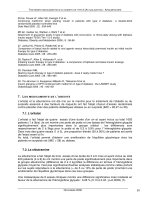
The terminal branches of the basilar artery are the posterior cere-
bral arteries, which supply the occipital (visual) cortex (Figs. 7.2 (g),
7.23 (b)). Many smaller branches arise from the basilar arteries, which
are too small to be shown at angiography. These “perforating” arteries
pass posteriorly to the brainstem. It is also the case that similar very
small arteries arise from all of the major intracerebral arteries, includ-
ing the communicators.
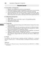
Vascular territories
Knowledge of the cerebral arterial territories can be of assistance in
the identification of a lesion as an infarct. These are illustrated in
Fig. 7.32.
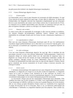
Cerebral venous drainage
A complex venous system drains blood from the brain into the inter-
nal jugular veins in the neck (Fig. 7.33).
The superficial veins over the cerebral surface drain into the dural
venous sinuses, venous spaces within the dura (Fig. 7.27). There is
also a deep system draining into the paired internal cerebral veins
(Figs. 7.2(i), 7.8, 7.17, 7.23(g)). The internal ceebral veins lead into the
single great vein of Galen, thence into the straight sinus. This venous
“confluence” is situated in the quadrigeminal plate cistern. Another
confluence, this time, of the dural venous sinuses occurs at the inter-
nal occipital protuberance or torcula, where the superior sagittal,
transverse and straight sinuses converge.
Fig. 7.32. The vascular
territories.
The skull and brain paul butler
80
Superior sagittal sinus
Inferior sagittal sinus
(a) (b)
Internal cerebral vein
Great vein of Galen
Straight sinus
Transverse sinus
Sigmoid sinus
Internal jugular vein
(a),(b)
(c)
Fig. 7.33. The cerebral venous system: (a) T1 weighted sagittal MRI after
intravenous gadolinium DTPA; (b) carotid angiogram, venous phase, lateral view;
(c) carotid angiogram, venous phase, frontal view. Note that the lateral sinuses
are not seen on the MRI because it is a midline “slice.” The angiograms
represent a 3-D arrangement displayed in 2-D.
Superior sagittal sinus
Lateral sinus
Internal jugular vein
81
Imaging considerations
The bony orbit is best examined with CT and images acquired in the
coronal plane are particularly useful to identify fractures. The radia-
tion dose to the lens is not insignificant and cataract formation is a
potential hazard
Plain radiography of the orbit is largely reserved for identifying
metallic intraocular bodies prior to MRI scanning.
Intraorbital fat is hypodense (dark) on CT scans and provides a useful
contrast to the other soft tissue structures within the orbit. Conversely
fat is hyperintense (white)on both T1- and T2-weighted MRI. The relative
brightness of fat can obscure the orbital contents and, to counter this
“fat-suppressed” MR, pulse sequences are used, usually in combination
with intravenous gadolinium DTPA. These render fat hypointense (dark)
and thus improve visualization of the globe, extraocular muscles, and
lacrimal gland. Overall, the soft tissue detail with MRI is superior to CT.
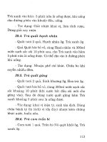
Anatomy of the bony orbit
The orbital cavity is shaped like a pyramid with its apex posteromedi-
ally and base anterolaterally, opening onto the face. It is represented
diagrammatically in Fig. 8.1. The bony margins separate it from the
anterior cranial fossa and frontal air sinus superiorly, the ethmoid and
sphenoid air sinuses medially, the maxillary sinus inferiorly, and the
temporal fossa laterally (Fig. 8.2).
Section 4
The head, neck, and vertebral column
Chapter 8 The eye
CLAUDIA KIRSCH
Applied Radiological Anatomy for Medical Students. Paul Butler, Adam Mitchell, and Harold Ellis (eds.) Published by Cambridge University Press. © P. Butler,
A. Mitchell, and H. Ellis 2007.
Superior orbital
fissure
Optic canal Greater wing
of sphenoid
Orbital plate
of ethmoid bone
Lacrimal bone
Nasal bone
Orbital plate
of maxilla
Lesser wing
of sphenoid
Zygoma
Roof
Medial
wall
Floor
Lateral
wall
Fig. 8.1. Diagram of the bony anatomy of the orbit.
Fig. 8.2. Coronal CT scan to show the orbital wall and extraocular muscles.
Superior rectus/levator
palpebrae superioris
muscles
Superior
ophthalmic
vein
Nasociliary
nerve
Superior
oblique
muscle
Medial
rectus
muscle
Crista
galli
Ethmoid
sinuses
Frontal
bone
Temporal
fossa
Lateral
wall of
orbit
Infraorbital
groove
Ostiomeatal
complex
Lamina
papyracea
Inferior rectus
muscle
Optic
nerve
Intraconal
fat
Lateral
rectus
muscle
The eye claudia kirsch
82
Orbital
septum
Medial rectus muscle
Cornea
Aqueous
Lens
Vitreous
Outer coats
of eye
Optic disc
(intraocular
optic nerve)
Lateral
rectus
muscle
Ophthalmic
artery
Optic nerve
(intraorbital)
in meningeal
sheath
Optic nerve
(intracanalicular)
Optic nerve
(intracranial)
Sphenoid
sinus
Anterior
clinoid
process
Superior
orbital
fissure
Intraconal fat
Extraconal fat
Inferior pole of
lacrimal gland
Fig. 8.4. Axial CT scan (inferior to Fig. 8.3), at the level of the superior orbital
fissure.
Lacrimal sac
Anterior lacrimal
crest (maxilla)
Ethmoid
sinuses
Insertion of
inferior oblique
muscle
Temporal
fossa
Greater wing
of sphenoid
Middle cranial fossa
(temporal lobe)
Pituitary gland
Fat in
cavernous
sinus
Sphenoid
sinus
Superior
orbital
fissure
Inferior rectus
muscle
Orbital fat
Inferior portion
of eye
Air beneath
lower lid
Zygoma
The triangular orbital floor, which slants laterally, and the rectangu-
lar medial orbital wall, the descriptively named lamina papyracea, are
both thin. The floor also has a groove running anteriorly to a canal,
the infraorbital foramen, transmitting the infraorbital nerve, con-
tributing further to its potential weakness. Predictably both the
medial wall and floor are prone to fractures and are demonstrated
optimally by coronal CT scans.
The lateral wall, also triangular is the thickest and is formed largely
from the zygomatic bone.
At the orbital apex, the optic canal, contained within the lesser
wing of the sphenoid bone, transmits the optic nerve, sympathetic
fibers and ophthalmic artery, opening posteriorly into the middle
cranial fossa (Fig. 8.3).
The superior orbital fissure (SOF), is located inferior and lateral
to the optic canal and is separated from the optic canal by the optic
strut (Fig. 8.4). The SOF is formed superiorly by the lesser wing of the
sphenoid bone and inferiorly by the greater wing. The SOF transmits
the oculomotor (IIIrd), trochlear (IVth), and abducent (VIth) cranial
nerves, the terminal ophthalmic nerve branches, and ophthalmic
veins.
Seen from the front, the inferior orbital fissure (IOF), forms a V-shape
with the SOF, its apex pointing medially.
The SOF communicates posteriorly with the cavernous sinus and
the IOF with the pterygopalatine fossa, which leads to the infratempo-
ral fossa. The veins crossing these fissures thus provide possible routes
for the spread of orbital infections both intracranially and into the
deep facial structures.
The periorbita is composed of the bony orbit periosteum and serves
as a protective barrier against spread of infection or neoplasms.
Posteriorly it merges with the optic nerve dura. Anteriorly, the perior-
bita continues as the orbital septum inserting on the tarsi within each
of the eyelids. Each tarsus is a fibrous structure, one in the upper, one
in the lower eyelid. In the upper eyelid, the orbital septum also joins
the tendon of the levator palpebrae muscle.
A preseptal orbital infection in front of the orbital septum may
be managed medically. A postseptal infection has spread behind
the septal barrier with loss of the normal orbital tissue planes and
is at risk for subperiosteal, intracavernous, and intracranial extension.
Soft tissues of the orbit
The soft tissues of the orbit are embedded in a fatty reticulum.
The globe is approximately 2.5 cm in diameter (Fig. 8.5). It is situated
Fig. 8.3. Axial CT scan at the level of the optic canals.
The eye claudia kirsch
83
Fig. 8.5. Fat-suppressed T1W axial MRI to show the globe.
Aqueous
Cornea
Ciliary body
Vitreous
Orbital fat
Medial rectus
muscle
Internal
carotid
artery
Lateral rectus
muscle
Optic disc
Lacrimal
gland
Choroid/sclera
Capsule and
nucleus of lens
Ophthalmic
artery
anteriorly within the orbit and has three coats enclosing its contents.
From the outside in, there are the tough, fibrous sclera, the vascular,
pigmented choroid, and the retina. These cannot be resolved sepa-
rately on routine CT and MRI. The vascular choroid can be identified
as a “blush” during carotid angiography.
Anteriorly within the globe, the circumferential ciliary body sup-
ports the lens and, anterior to the lens, the iris.
The lens demarcates two compartments, the anterior aqueous
and posterior vitreous. The iris further divides the aqueous
(incompletely because of the pupil), into anterior and posterior
chambers. The cornea forms the anterior boundary of the anterior
chamber.
The episcleral membrane, or Tenon’s capsule, encapsulates the
posterior four-fifths of the globe, dividing it from the posterior
orbital fat.
The optic nerve
The optic nerve is not a true cranial nerve. Rather, it is a cerebral
white matter tract. It arises from the posterior globe and pursues
an undulating course within the rectus muscle cone to pass
through the optic canal accompanied by the ophthalmic artery
(Fig. 8.6). Each optic nerve is about 4.5 mm in diameter and 5 cm
long. The distance from the posterior globe to the optic canal is
about 2 cm. This redundancy permits the nerve mobility with the
eye movements.
Belying its nature the optic nerve is surrounded by cerebrospinal
fluid and encased in a meningeal sheath.
The extraocular muscles
Six striated extraocular muscles, four rectus muscles, and two oblique
muscles are responsible for the eye movements. The extraocular
muscles are arranged as a cone and define intra- and extraconal
compartments.
The four rectus muscles arise from the annulus of Zinn, a tendi-
nous ring at the optic foramen. The annulus is composed of four
extraocular muscles: superior rectus, medial rectus, and inferior, and
lateral rectus muscles (Fig. 8.2). The oblique muscles have a more
complex course. The superior oblique muscle, the longest and
thinnest of all orbital muscles, originates from the sphenoid bone
periosteum extending along the superior medial orbital wall as a
slender tendon. The muscle enters the trochlea (L. pulley), a small
fibrocartlaginous ring, sharply turning posterolaterally and inferiorly
behind the superior rectus muscle inserting on the lateral sclera. The
inferior oblique muscle originates from the medial portion of the
anterior orbital floor and is inserted into the lateral aspect of the
eyeball.
The triangular levator palpebrae superioris muscle arises above and
in front of the optic canal to pass forwards above superior rectus to
insert into the upper eyelid.
The nerves of the orbit
The superior oblique muscle is supplied exclusively by the trochlear
(IVth) cranial nerve and lateral rectus by the abducent (VIth) cranial
The eye claudia kirsch
84
Fig. 8.6. Fat-suppressed T1W axial MRI to show the optic nerve.
Ciliary body
Aqueous
Cornea
Optic disc
Optic nerve
sheath
Optic nerve
Internal
carotid
artery
Ophthalmic
artery
Malar process
of frontal bone
Orbital plate
of frontal bone
Superior plate
of frontal bone
Nasociliary
nerve
Region of
cribriform plate
Superior oblique
tendon
Levator palpebrae
superioris muscle
Lamina papyracea
(ethmoid bone)
Vitreous
External coats
of eye
Floor of orbit
Maxillary
antrim
Lacrimal
bone
Nasolacrimal
duct
Inferior
oblique
muscle
Orbital fat
Medial rectus
muscle
Lacrimal
gland
Fig. 8.7. Coronal CT scan (anterior to Fig. 8.2), to show the lacrimal glands.
nerve. The oculomotor (IIIrd) cranial nerve supplies the remaining,
striated, extraocular muscles. Sensory innervation is via the oph-
thalmic division and maxillary divisions of the trigeminal (Vth) cranial
nerve.
The lacrimal gland
The almond-shaped lacrimal gland is located anterolaterally in the
roof of the orbit in a small fossa (Fig. 8.7). It forms tears, which diffuse
to the conjunctiva and drain via the tear ducts running in the medial
portions of the margins of the upper and lower lids.
The orbital vasculature
The main arterial supply of the orbit is via the ophthalmic artery,
which arises directly from the internal carotid artery, in the majority
of cases just after it has exited the cavernous sinus (Fig. 8.8). It passes
forward to enter the orbit through the optic canal, accompanying the
optic nerve within the dural sheath. Initially inferior to the nerve, the
ophthalmic artery crosses the nerve to lie medial to it (Fig. 8.9). It
gives off numerous branches within the orbit including the central
artery of the retina. Further arterial supply is provided by branches
of the external carotid artery.
The eye claudia kirsch
85
Fig. 8.10. Axial CT scan (superior to Fig. 8.9), to show the superior ophthalmic
veins.
Upper lid
Orbital veins
Upper part of eye
Top of
lacrimal
gland
Superior
oblique
muscle
Superior
rectus
muscle
Superior
ophthalmic
vein
Orbital fat
Fig. 8.9. Axial CT scan to show the ophthalmic arteries.
Medial rectus
muscle
Lateral rectus
muscle
Lacrimal gland
Optic nerve
Ophthalmic
artery
Superior
orbital
fissure
There are two major veins within the orbit. Both are valveless.
The superior ophthalmic vein forms posteromedial to the upper
eyelid, from facial veins. It courses posteriorly, close to the oph-
thalmic artery, to enter the cavernous sinus through the superior
orbital fissure (Fig. 8.10).
The inferior ophthalmic vein forms in the anterior orbital floor and
usually joins the superior ophthalmic vein.
The optic pathways
The optic nerves extend posteriorly from the optic canal, ascending
medially at a 45 degree angle. They then then fuse to form the
optic chiasm, which is superior to the pituitary gland and may be
compressed by a large pituitary tumor extending upwards. From the
optic chiasm the two optic tracts pass posterolaterally (refer to
Fig. 8.1(g),(h), see Chapter 7 Figs. 7.17, 7.90). These then merge with
the hemispheres, becoming indistinguishable on routine CT or MRI.
Visual fibers pass posteriorly through the temporal lobes to the visual
cortex within the occipital lobes, thus running a long intracranial
course.
Fig. 8.8. Carotid angiogram, lateral projection, to show the ophthalmic artery.
Lacrimal artery
Supraorbital artery
Intracanalicular
segment of
ophthalmic artery
Terminal
branches
Inferior muscular
arteries
Internal carotid
artery
Ciliary arteries
86
The anatomy of the ear is conveniently described as comprising three
parts: the external ear, the middle ear, and the inner ear.
The external ear
The external ear consists of the pinna or auricle and the S-shaped
external auditory canal, extending from the auricle to the tympanic
membrane.
The outer third of the external auditory canal is fibrocartilagenous
and contains numerous hairs and glands for producing cerumen. The
inner two-thirds are bony and contains few hairs or cerumen glands.
The tympanic membrane separates the external auditory canal from
the middle ear and is embedded in the bone of the tympanic ring. It is
in two parts: a smaller, looser and thicker pars flaccida superiorly, and
a larger, tenser, fibrous pars tensa inferiorly. The scutum represents the
superior tympanic ring to which the tympanic membrane is attached.
It is particularly well seen on coronal thin section CT (Fig. 9.1).
The middle ear
The middle ear, or tympanic cavity, is a treasure trove of spaces,
bumps, and recesses. The lateral wall of the tympanic cavity is
formed almost completely by the tympanic membrane and is subdi-
vided into three spaces relative to it: from above down, the epitympa-
num (syn. the attic or epitympanic recess), mesotympanum, and
hypotympanum.
Section 4
The head, neck, and vertebral column
Chapter 9 The ear
CLAUDIA KIRSCH
Applied Radiological Anatomy for Medical Students. Paul Butler, Adam Mitchell, and Harold Ellis (eds.) Published by Cambridge University Press. © P. Butler,
A. Mitchell, and H. Ellis 2007.
Fig. 9.1. Coronal HRCT, the petrous bone, (a) is anterior to (b).
Facial nerve segments
Tympanic Labyrinthine
Cochlea
Styloid process
(a)
(b)
Tegmen
tympani
Superior semicircular canal
Vestibule
IAM
EAM
Lateral semicircular canal
IAM
EAM
Facial nerve (tympanic segment)
Oval
window
Scutum
Promontory
Basal turn
of cochlea
Facial nerve (tympanic segment)
The ear claudia kirsch
87
The epitympanum is located above the tympanic membrane. The
mesotympanum is at the same level as the tympanic membrane and
the hypotympanum is located below it.
The roof of the middle ear cavity is known as the tegmen tympani,
which separates the tympanic cavity below from the middle cranial
fossa above. The floor also consists of a thin plate of bone below which
is the bulb (superior part) of the internal jugular vein.
A bony wall separates the tympanic cavity medially from the inner
ear. In the epitympanum is a prominence due to the lateral semicircu-
lar canal and, inferior to this prominence, is the facial nerve canal. On
the medial wall also, but more anterior and just opposite the tym-
panic membrane, is the cochlear promontory, created by the large
first turn of the cochlea. The medial wall also contains two small
windows. Above the promontory, the oval window is apposed by the
footplate of the stapes, vibrations from which are transmitted to
the inner ear. Located inferior to the oval window and below the
promontory is the round window, closed by a secondary tympanic
membrane, allowing for counter pulsation of the perilymph fluid.
From the anterior wall of the tympanic cavity, the pharyngolym-
panic (Eustachian) tube travels anteromedially to open into the
pharynx (Fig. 9.2). On the posterior wall is a prominent ridge, the
pyramidal eminence, in which there is an aperture transmitting the
stapedius tendon. Lateral to the pyramidal eminence is the facial
nerve recess, medial to it the sinus tympani.
The posterior wall of the tympanic cavity has a superior opening,
the aditus ad antrum (Fig. 9.3). This leads posteriorly from the epitym-
panic recess into the mastoid air cells and is a pathway for the spread
of disease between the middle ear and mastoid process.
Within the middle ear cavity is the ossicular chain consisting of the
descriptively named malleus (L. hammer), incus (L. anvil), and stapes
(L. stirrup), each connected by synovial joints (Figs. 9.4 and 9.5).
Eustachian
tube
Fig. 9.2. Axial HRCT to show the eustachian or pharyngotympanic tubes.
Fig. 9.3. HRCT
reformatted in the
sagittal plane to show
the aditus ad antrum.
Aditus
Incus
Malleus
Temporomandibular
joint
Facial nerve canal
(vertical segment)
Post. Ant.
Head
Anterior process
Lateral process
Manubrium
Lateral
Body
Short limb
Long limb
Lenticular process
Medial
Oval window
niche
Footplate
Head
I
M
M
S
Fig. 9.4. Diagram of the auditory ossicles.
Fig. 9.5. Axial HRCT
showing the ossicular
chain.
Malleus
Incus
Stapes
The ear claudia kirsch
88
The malleus has a lateral short process and manubrium embedded
within the tympanic membrane, and head and neck, best seen on thin
section coronal CT images. A small diathrodial joint exists between
the malleus and incus within the attic.
The largest ossicle is the incus, posterior to the malleus (Fig. 9.3),
composed of a body, with a short process extending posteriorly
acting as a fulcrum allowing the incus to rotate. The incus
has a lenticular and a long process meeting at about
a 90-degree angle.
The cup-shaped lenticular process connects to the ball-shaped head
of the stapes (capitulum) via a tiny cartilaginous disc, forming a tiny
synovial diathrodial communication. The stapes footplate is attached
to the oval window via an annular ligament.
The best way to see the ossicular chain is on thin section axial and
coronal CT bone windows.
Two important muscles protect the ossicles from loud noises.
The stapedius muscle, supplied by facial (VIIth cranial) nerve,
stretches the annular ligament of the stapes. It arises from the pyrami-
dal eminence and attaches to the stapes footplate.
The tensor tympani muscle, supplied by the trigeminal (Vth cranial)
nerve, dampens sounds by tightening the tympanic membrane. The
tensor tympani muscle lies parallel and medial to the eustachian tube.
It sits in a bony sulcus, extending from the pyramidal eminence ante-
riorly to attach on to the stapes footplate.
The inner ear
The inner ear or vestibulocochlear organ is responsible for hearing
and balance. It is well protected and contained within the petrous
portion of the temporal bone. The bony labyrinth of the inner
ear encloses the membranous labyrinth, which contains fluid
known as endolymph.
The bony labyrinth comprises the cochlea, vestibule, and semicir-
cular canals and is best appreciated on CT (Figs. 9.1 and 9.6). The
cochlea (L. snail shell), is anterior to the vestibule and semicircular
canals. It is shaped like a spiral seashell, making two and half turns
around its bony central core called the modiolus (L. nave of the
wheel), which has small openings for blood vessels and nerves. The
bony labyrinth encloses the membranous labyrinth, which com-
prises the saccule and utricle (not visible on imaging), contained
within the vestibule, three semicircular ducts, located within the
three semicircular canals, and the cochlear duct located within the
cochlea. These sacs and ducts contain endolymph and are end
organs for hearing (cochlea) and balance (semicircular canals).
Between the bony labyrinth and the membranous labyrinth is fluid
known as perilymph. Because these are fluid-containing structures,
they are best visualized on MRI, using T2-weighted sequences
(Figs. 9.7 and 9.8).
The vestibule communicates posteriorly with the semicircular
canals and with the posterior fossa via the vestibular aqueduct. The
vestibular aqueduct contains the endolymphatic duct, which extends
through posterior cranial fossa into a blind pouch, called the
Fig. 9.6. Axial HRCT
showing the bony
labyrinth.
Cochlea
Vestibule
Facial nerve
tympanic segment
Incudomallear
articulation
Lateral
semicircular
canal
Vestibular aqueduct
(posterior opening)
Posterior cerebral artery
Superior cerebellar artery
Pons
Cochlea
Anterior inferior cerebellar a.
Vertebrobasilar confluence
Fig. 9.7. Coronal T2 weighted MRI through the cochleae.
The ear claudia kirsch
89
Fig. 9.8. Coronal T2 weighted MRI through the vestibules.
Pons
Tentorium cerebelli
Cerebellopontine
angle cistern
Anterior
Lateral
Posterior
Vestibule
Semi-
circular
ducts
Posterior semicircular canal
Lateral semicircular canal
Anterior semicircular canal
Vestibule
Cochlea
Fig. 9.9. Diagram of the bony labyrinth.
Fig. 9.10. Axial T2 weighted MRI to show the facial (VIIth cranial) and
vestibulocochlear (VIIIth cranial) nerves within the internal auditory meatus.
Facial nerve
Auditory
nerve
Basilar artery
Cochlea
Vestibule and lat.
semicircular duct
Petrosal vein of Dandy
Cerebellopontine angle cistern
endolymphatic sac, located below the dura mater along the posterior
petrous temporal bone.
The three semicircular canals (Fig. 9.9) are superior and posterior
to the vestibule, with which they communicate. They are arranged
at right angles to one another as the superior (anterior), horizontal
(lateral), and posterior semicircular canals. There are only five
entrances into the vestibule because the superior and posterior canals
share a common limb (the common crus). The anterior or superior
semicircular canal is at a right angle to the long axis of the petrous
temporal bone. The posterior semicircular canal runs parallel to the
axis of the petrous temporal bone in close relation to the sigmoid
sinus. The horizontal semicircular canal is located just above the facial
nerve canal in the middle ear.
The internal auditory canal
The internal auditory canal or meatus (IAM) is separated laterally
from the inner ear via a thin plate of bone, containing openings
for the facial (VIIth cranial) nerve and the vestibulocochlear (VIIIth
cranial) nerve. The internal auditory canal is a round opening
into the posterior cranial fossa and is divided into quadrants. The
bony crista falciformis divides the IAM horizontally. Bill’s bar
divides the canal vertically. The facial (VIIth cranial) nerve is located
anteriorly and superiorly. The cochlear division of the eighth nerve
is located anteriorly and inferiorly. Located in the posterior canal
are the superior and inferior quadrants and the remaining
divisions of the eighth nerve, the superior and inferior vestibular
nerves.
The facial nerve
The facial nerve follows a complex course within the petrous bone. It
may therefore be damaged by trauma to the petrous bone, including
surgery, and by, for example, middle ear infections.
It arises from the brainstem and crosses the cerebellopontine
angle cistern in an anterolateral direction, accompanying the
vestibulocochlear (VIIIth cranial) nerve into the internal auditory
meatus (Fig. 9.10). The facial nerve then enters its canal turning
more anteriorly towards the geniculate ganglion (the labyrinthine
portion), (Fig. 9.11). It then turns sharply posterolaterally, at the fist
genu (L. knee) to course along the medial wall of the middle ear
cavity (the tympanic portion) just below the lateral semicircular
canal and above the oval window niche (Fig. 9.1). At the second genu,
the facial nerve makes a second sharp turn, descending vertically to
exit via the stylomastoid foramen in the mastoid bone (Fig. 9.3) divid-
ing in the parotid gland into five branches supplying the muscles of
facial expression.
The ear claudia kirsch
90
Fig. 9.11. Axial HRCT to
show the facial nerve
canal.
The cerebellopontine angle cistern
The cerebellopontine angle cistern is one of the large, interconnect-
ing cerebrospinal fluid spaces (cisterns) at the base of the brain. It is
a subarachnoid space whose medial margin is the pons, and whose
lateral margins include the posterior petrous bone. Traversing the
cistern are the facial (VIIth cranial) and the vestibulocochlear (VIIIth
cranial) nerves. The anterior–inferior cerebellar artery, (AICA), a loop
from which can occasionally enter the IAM, the petrosal vein of
Dandy and the trigeminal (Vth cranial) nerve may also occur within
the cistern.
Facial nerve tympanic segment
Aditus ad antrum
Facial nerve –
labyrinthine
segment
91
The facial skeleton and musculature
For imaging, the skull and facial bones are best considered as a whole
(Fig. 10.1). For descriptive purposes, they are usually divided into the
upper face, consisting of the supraorbital ridge and frontal bone; the
midface extending from the supraorbital margin to the upper jaw;
and the lower face comprising the mandible.
Plain radiographs are still commonly performed. The occipito-
mental or Water’s view (Fig. 10.2), occipito-frontal (Fig. 10.3) and lateral
views (Fig. 10.4) are the usual projections. Increasingly, 3-D CT is sup-
planting radiographs for facial trauma. CT is also ideal for examining
the skull base, pterygopalatine and infratemporal fossae (Fig. 10.5).
The mandible and temporomandibular joint
The mandible (Fig. 10.6) is the strongest of the facial bones and is par-
ticularly well shown by dental panoramic radiography (or orthopanto-
mography) (Fig. 10.7). The teeth are borne by the inferior alveolar
process. The mandibular foramen lies on the inner surface of the
ramus and admits the inferior alveolar nerve (trigeminal) into the
mandibular canal, which opens on the outer surface of the mandible
as the mental foramen.
The muscles of the tongue and floor of the mouth are attached to
the inner surface of the body of the mandible. The powerful muscles
of mastication insert on the ramus and angle.
Section 4
The head, neck, and vertebral column
Chapter 10 The extracranial head and neck
JUREERAT THAMMAROJ
and JOTI BHATTACHARYA
Applied Radiological Anatomy for Medical Students. Paul Butler, Adam Mitchell, and Harold Ellis (eds.) Published by Cambridge University Press. © P. Butler,
A. Mitchell, and H. Ellis 2007.
Supraorbital
foramen
Frontal bone
Supraorbital
ridge
Greater wing of
sphenoid
Infraorbital
foramen
Zygoma
Maxilla
Mental
foramen
Fig. 10.1(a),(b). Diagram of skull and facial skeleton. (a) frontal view, (b) lateral view.
Bregma
Frontal bone
Pterion
Glabella
Nasion
Lacrimal
bone
Nasal bone
Zygoma
Anterior
nasal spine
Maxilla
Mental
foramen
Angle of mandible
Infratemporal fossa
Pterygoid process
Temporomandibular
joint
Temporal fossa
(a) (b)
The extracranial head and neck jureerat thammaroj and joti bhattacharya
92
Fig. 10.2. Occipito-mental
radiograph (Water’s
view). The petrous
ridges should be
projected just below the
maxillary antra. This is
the best single view for
the antra. Note the
lucency of the canal for
the posterior superior
alveolar nerve in the
lateral antral wall.
Fig. 10.3. Occipito-frontal radiograph (Caldwell view). The petrous ridges should
be projected over the lower third of the orbit. This is the best frontal view for
the ethmoid and frontal sinuses. Note the foramen rotundum always lying
immediately below the superior orbital fissure.
Floor of
pituitary
fossa
Planum
sphenoidale
Crista galli
Frontal sinus
Lesser wing
of sphenoid
Greater wing
of sphenoid
Ethmoid sinus
Innominate
line
Superior
orbital
fissure
Foramen
rotundum
Petrous
ridge
Lateral border
of lateral
pterygoid
process
Lateral orbital roof
Medial orbital roof
Pituitary fossa
Sphenoid sinus
Middle concha
Posterior wall
of maxillary
sinus
Hard palate
Soft palate
Prevertebral
soft tissues
V-shaped
zygomatic
recess of
maxillary
sinus
Inferior concha
Fig. 10.4. Lateral radiograph of facial bones. Note the V-shaped shadows of the
zygomatic recesses of the maxillary antra and the shadows of the middle and
inferior turbinates. The posterior walls of both antra are visible.
Fig. 10.5(a)–(g). Series of CT images of skull base demonstrating the
pterygopalatine and infratemporal fossae and related anatomy. Images are
contiguous from inferior to superior. The lowest scan (a) shows the
pterygopalatine canal which communicates with the mouth. The
sphenopalatine foramen is seen in (e) opening into the nasal cavity posterior to
the middle turbinate. The horizontal canals of the foramen rotundum (g) and the
vidian (pterygoid) canal (e) link the fossa to the middle cranial fossa and the
foramen lacerum, respectively. The lateral opening of the pterygopalatine fossa
into the infratemporal fossa is called the pterygomaxillary fissure.
(a)
Inferior concha
Medial
and lateral
pterygoid
processes
Nasopharynx
Occipital
condyle
Styloid
process
Pterygopalatine
canal
The extracranial head and neck jureerat thammaroj and joti bhattacharya
93
(b)
(d) (e)
(f) (g)
(c)
Pterygopalatine
fossa
Stylomastoid
foramen
Zygomatic
recess
Naslacrimal
duct
Infratemporal
fossa
Pterygopalatine
fossa
Vidian
(pterygoid)
canal
Foramen
ovale
Carotid
canal
Foramen
lacerum
Inferior orbital
fissure
Sphenopalatine
foramen
External
auditory
meatus
Clivus
Foramen
spinosum
Pterygopalatine
fossa
Infratemporal
fossa
Head of
mandible
Hypoglossal
canal
Nasolacrimal
duct
Pterygopalatine
fossa
Zygomatic
arch
Carotid
canal
Temporo
mandibular
joint
Jugular
foramen
Pterygopalatine
fossa
Foramen
ovale
Eustachian
tube
External
auditory
meatus
Petrous portion
of carotid canal
Pterygopalatine
fossa
Foramen
rotundum
Temporal
fossa
Middle
cranial
fossa
Internal
auditory
meatus
Carotid
canal
Fig. 10.5(a)–(g). Continued
The extracranial head and neck jureerat thammaroj and joti bhattacharya
94
Coronoid
process
Condyle/head
Mandibular
notch
Neck
Angle
Mental
foramen
Mental
protuberance
Alveolar
process
Mandibular
foramen
Fig. 10.6. Diagram of
mandible. The masseter
and medial pterygoid
muscles insert on the
outer and inner aspects
of the angle. The lateral
pterygoid muscle inserts
on the neck and the
temporalis inserts on
the coronoid process.
Fig. 10.7. Orthopantomography, or dental panoramic radiograph of the mandible
and maxilla. This technique in which the X-ray tube and film cassette rotate
synchronously and reciprocally around the patient’s head gives a good survey
of the upper and lower jaws.
Nasal septum
Hard palate
Zygomatic
recess
Maxillary
sinus
Coronoid process
of mandible
Temporo
mandibular
joint
Styloid
process
Mandibular
canalPeriodontal
membrane
Lamina
dura
Medial
Lateral
Incisor
Canine
1st
2nd
Premolar
3rd 2nd 1st
Molar
(a)
(b)
The mandibular condyle articulates with the mandibular fossa of the
temporal bone at the temporomandibular joint (TMJ) (Fig. 10.5 (c)–(e)).
Nasal cavity
The external nose consists of superior bony and inferior cartilaginous
portions. The nasal cavity extends from the skull base to the roof of
the mouth and is divided by the nasal septum into two fossae, which
communicate via the choanae with the nasopharynx posteriorly,
and laterally with the paranasal sinuses. This region is best demon-
strated by CT (Fig. 10.5). The nasal cavity is roofed in its mid-portion by
the cribriform plate of the ethmoid bone which is perforated by about
20 foramina for the olfactory nerve, and ethmoidal vessels. The hard
palate forms the floor. The lateral wall is complex bearing the three
turbinates (or conchae) and their corresponding meatuses (Fig. 10.8).
The paranasal sinuses and ostiomeatal complex
The paranasal sinuses (frontal, maxillary, ethmoid, and sphenoid) arise
as outgrowths of the nasal cavity and communicate with the cavity via
ostia. Although well seen on radiographs (Figs. 10.2–10.4), their anatomy
and pathology is best appreciated on coronal CT images.
The pyramid-shaped maxillary sinus, or antrum, lies within the
body of the maxilla (Fig. 10.9). The roots of the molar and premolar
teeth may project into the sinus but are usually covered by a thin
layer of mucosa. Posteriorly lies the pterygopalatine fossa. The maxil-
lary ostium is in the superior part of the medial wall and opens into
the ethmoid infundibulum, a narrow channel between the uncinate
process and the ethmoid bulla. This in turn opens into a curved
groove in the middle meatus below the ethmoid bulla: the hiatus
semilunaris (Fig. 10.8(b)). The frontal sinus opens into the anterior
end of this groove, with the ethmoid cells opening more posteriorly.
These structures, known as the ostiomeatal complex, form the
drainage pathway for secretions from the sinuses; obstruction here
Agger nasi crest
Superior concha
Sphenoethmoidal
recess
Sphenopalatine
foramen
Middle concha
Inferior concha
Orifice of
Eustacian
tube
Fig. 10.8(a),(b). Diagrams of lateral wall of nasal fossa, (a) before and (b) after
removal of the turbinates to expose the underlying meati. Note that only the
posterior ethmoid cells open into the superior meatus and only the
nasolacrimal duct opens into the inferior meatus.
Frontal recess
Anterior
ethmoid
ostia
Posterior ethmoid ostia
Ethmoid bulla
Sphenopalatine
foramen
Middle
ethmoid
ostia
Maxillary
sinus
ostium
Hiatus semilunaris
and ethmoid
infundibulum
Nasolacrimal
duct ostium
The extracranial head and neck jureerat thammaroj and joti bhattacharya
95
Frontal sinus
Nasal bone
Septal
swell
body
Lacrimal
fossa
Crista galli
Anterior
ethmoid
air cells
Bulla
ethmoidalis
Cribriform
palate
Middle
turbinate
Inferior meatus Inferior turbinate Lacrimal duct
Maxillary
antrum
Ostium of
maxillary sinus
Uncinate
process
Ethmoid
infundibulum
Superior
turbinate
Middle
turbinate
Orifice of
nasolacrimal
duct
Inferior
turbinate
Uncinate
process
Ethmoid infundibulum
openng into hiatus
semilunaris
Zygomatic
process
(a) (b)
Sphenoethmoidal
recess
Anterior
clinoid process
Planum
sphenoidale
turbinates
Superior
orbital fissure
Inferior
orbital fissure
Maxillary antrum
Inferior turbinate
Uncinate
process
Superior
Middle
Zygomatic
recess
Middle
turbinate
Inferior
turbinate
Hard palate
Maxillary
antrum
Zygomatic
process
Infratemporal
fossa
Coronoid
process
Temporal
fossa
Sphenopalatine
foramen
Pituitary fossa
Dorsum sellae
Sphenoid sinus
Zygomatic recess
Fig. 10.9(a)–(f). Coronal CT
series on bone window
settings demonstrating
the anatomy of the
paranasal sinuses and
ostiomeatal complex
from anterior (a) to
posterior (f).
(c)
(d)
(e) (f)
The extracranial head and neck jureerat thammaroj and joti bhattacharya
96
thus has a pivotal role in the development of sinusitis and endoscopic
sinus surgery seeks to clear these obstructions.
The oral cavity tongue and salivary glands
The oral cavity contains the teeth, tongue and salivary glands, while
posteriorly lies the pharynx. The mylohyoid muscles (originating from
the mandible and inserting on the hyoid bone) form the “diaphragma-
oris,” which divides the floor of the mouth into a sublingual space
superomedially and a submandibular space inferolaterally (Fig. 10.10).
The tongue is a muscular organ, supplied by the hypoglossal nerve
and readily identified on CT and MRI.
The parotid gland is the largest of the three, and lies over the
ramus of the mandible and masseter muscle (Fig. 10.11) with its deep
portion curling around the mandible. It is traversed by the facial nerve
which divides here into its five terminal branches. The course of the
nerve divides the gland into superficial and deep lobes. The facial
nerve is seldom visible on imaging studies, although its course can be
traced. The fatty structure of the parotid gives it a CT density between
that of muscle and fat. On MRI scans, the gland is hyperintense to
muscle.
The submandibular gland is the principal structure in the sub-
mandibular space. Because the gland wraps around the posterior
border of the mylohyoid, its deep portion lies in the sublingual space.
Its CT density is approximately that of muscle and higher than that of
the parotid gland. It shows strong contrast enhancement.
The sublingual gland is the smallest of the major salivary glands
lying anterior to the submandibular gland.
Teeth
Mandible
Hyoid bone
Lingual septum
Sublingual
gland
Mylohyoid
muscle
Masseter
muscle
Genioglossus
muscle
Intrinsic
tongue
muscle
Hard palate
Fig. 10.10. T1W MRI of the head coronal (a) and sagittal (b) demonstrating the structures of the floor of the mouth and tongue.
Longitudinal fibres
of tongue
Soft palate
Genioglossus
muscle
Hyoid bone
Transverse fibres
of tongue
Parapharyngeal space
Parotid gland
Posterior facial vein
External carotid artery
Carotid sheath
Fig. 10.11(a),(b). Contrast-enhanced axial CT through the parotid gland. Note the typical attenuation of the adult parotid gland in (a), intermediate between fat and
muscle density. In children and some adults the parotid can almost be isodense with muscle (b) which can make identification of mass lesions difficult.
Parapharyngeal
space
Medial pterygoid
muscle
Masseter
muscle
Mandible
Posterior facial vein
(lateral) and external
carotid artery (medial)
Parotid gland
Internal jugular
vein
Internal carotid
artery
(a)
(b)
(a) (b)