System Analysis, Design, and Development Concepts, Principles, and Practices phần 6 pptx
Bạn đang xem bản rút gọn của tài liệu. Xem và tải ngay bản đầy đủ của tài liệu tại đây (2.6 MB, 84 trang )
35.2 Commonly Applied System Design Objectives 407
Design-for-Efficiency
Some systems and products require focused consideration on efficient utilization of resources. In
these cases a Design-for-Efficiency objective must be established.
Design-for-Effectiveness
One of the key contributors to User satisfaction is a system, product, or service’s degree of
effectiveness. Did the missile hit and destroy the target? Does the flight simulator improve pilot
effectiveness? Establish Design-for-Effectiveness objectives where the effectiveness is the key
determinate for mission success.
Design-for-Reconfigurability
Some systems and products are designed to accommodate a variety of missions as well as a quick
turnaround between missions. Therefore, some may have to be reconfigurable within a specified
time frame.
Design-for-Integration, Test, and Evaluation Objective
Modular system and products that undergo multiple levels of integration and test require a Design-
for-Integration, Test, and Evaluation objective. Ideally, you would isolate each configuration item
(CI) and test it with actual, simulated, stimulated, or emulated interfaces. If the system or product
is to be integrated at various facilities, special interface considerations should be given to physical
constraints and equipment, and the tools available should be investigated.
Finally, EQUIPMENT-based systems and products must be designed to facilitate multi-level
system verification and validation. This requires the incorporation of temporary or permanent test
points and access ports for calibration and alignments among other things.
Design-for-Verification Objective
Once the system or product is integrated, tested, and ready to be verified, designers must consider
HOW the item will be verified. Some requirements can be physically verified; other requirements
may not. Establish a Design-for-Verification objective to ensure all data required for verification
are accessible and can be easily measured.
Design-for-Maintainability Objective
Single-use, multi-use, and multi-purpose systems require some form of Design-for-Maintainability
objective. This may include preventive maintenance, corrective maintenance, calibration, upgrades,
and refurbishment. Key design considerations include maintenance operator access and clearances
for hands, arms, tools, and equipment. Additional considerations include the availability of elec-
trical power, need for batteries, or electrical generators, external air sources for aircraft while on
the ground, and so on. These considerations emphasize the need for a Maintenance Concept to
provide a framework for deriving Design-for-Maintainability requirements.
Design-for-Disposal Objective
Systems and products that employ nuclear, biological, or chemical (NBC) materials and ultimately
wear out, become exhausted, damaged, or destroyed intentionally or by accident. In any case, the
system or product requires a Design-for-Disposal objective. This includes mechanisms for moni-
toring and removal of hazardous materials such as NBC substances or traces. For items that can
Simpo PDF Merge and Split Unregistered Version -
408 Chapter 35 System Design Objectives
be reclaimed and recycled, special tools and equipment—categorized as peculiar support equip-
ment (PSE)—may be required.
Design-for-Security-and-Protection Objective
Various systems and products require a Design-for-Security-and-Protection objective that limits
SYSTEM or product access to only authorized individuals or organizations. Design considerations
include layers of armor, Internet firewalls, and authorized accounts and passwords.
Design-for-Safety Objective
The application of SE requires strict adherence to laws, regulations, and engineering principles and
practices that promote the safety of system and product stakeholders—the operators, maintainers,
general public, personal property, and environment. The Design-for-Safety objective focuses on
ensuring that systems, products, and services are safe to deploy, operate, maintain, and dispose of.
This includes not only the physical product but also establishing training and instructional proce-
dures, cautionary warnings and notices, and potential consequences for violation.
Quality Function Deployment (QFD)
One method for sorting out customer needs and priority values is Quality Function Deploy-
ment (QFD). Where time permits, you are encouraged to consider and investigate QFD as part of
your analysis.
35.3 GUIDING PRINCIPLES
In summary, the preceding discussions provide the basis with which to establish the guiding prin-
ciples that govern system design objectives practices.
Principle 35.1 Every User has key Operations and Support (O&S) Phase objectives that a
SYSTEM/entity design must satisfy; collaborate with Users to understand their needs and priori-
tize them.
35.4 SUMMARY
Our discussions in this chapter highlighted the need to establish system design objectives practices to ensure
that User operational needs are met. These objectives form the basis for developing Mission Needs Statements
(MNSs), Statements of Objectives (SOOs), Operational Requirements Document (ORD), System Requirements
Documents (SRDs), and System Performance Specifications (SPS).
GENERAL EXERCISES
1. Answer each of the What You Should Learn from This Chapter questions identified in the Introduction.
2. Refer to the list of systems identified in Chapter 2. Based on a selection from the preceding chapter’s
General Exercises or a new system selection, apply your knowledge derived from this chapter’s topical
discussions. A User has employed your services to recommend the driving design “to/for” objectives for
the selected system or product.
(a) What are the top three or five objectives you would recommend?
(b) How would you prioritize each objective?
Simpo PDF Merge and Split Unregistered Version -
References 409
(c) Prepare a statement for a formal Request for Proposal (RFP) that expresses each objective and its
relative priority.
ORGANIZATIONAL CENTRIC EXERCISES
1. Contact a contract program in your organization.
(a) What are the User’s objectives for the system, product, or service?
(b) How were the objectives expressed? RFP? Contract?
(c) What are the objectives?
(d) How is the program implementing the objectives?
(e) What lessons has the program learned from this exercise?
REFERENCES
IEEE Std 610.12-1990. 1990. IEEE Standard Glossary of
Software Engineering Terminology. Institute of Electrical
and Electronic Engineers (IEEE). New York, NY.
Defense Systems Management College (DSMC) Ft. Belvoir.
VA. 2001. Glossary: Defense Acquisition Acronyms
and Terms, 10th ed. Defense Acquisition University
Press.
MIL-STD-882D. 2000. Standard Practice for System Safety.
Washington, DC: Department of Defense (DoD).
Simpo PDF Merge and Split Unregistered Version -
Chapter 36
System Architecture Development
36.1 INTRODUCTION
All human-made and living systems, by definition, are composed of interacting elements. Each
element has its own unique identity, capabilities, and characteristics, integrated into a purposeful
framework specifically arranged to accomplish a function or mission. The integrated, multi-level
framework of elements and combinations of elements represent the SYSTEM’s architectural con-
figuration or simply architecture.
This chapter explores the development of system architectures. As discussed in Part I on
System Analysis Concepts, the system architecture is an aggregate abstraction consisting of four
classes of architectures: 1) a requirements architecture, 2) an operations architecture, 3) a behav-
ioral architecture, and 4) a physical architecture.
Our discussions in this chapter establish the foundation for developing a system architecture.
Since the fundamental concepts of the architectural frameworks were covered in Part I on System
Architecture Concepts, this chapter focuses attention on physical configuration unique topics.
Topics include centralized, decentralized, and distributed processing; fault tolerant architectural
design; environmental, safety, and health (ES&H) considerations, fire detection and suppression;
and security and protection.
What You Should Learn from This Chapter
1. What is a system architecture?
2. What are the key attributes of an architecture?
3. What are the primary architectural views of a system?
4. Define the semantics of architectures.
5. What is centralized control processing architecture?
6. What is decentralized control processing architecture?
7. What is distributed processing architecture?
8. What is a fault tolerant architectural design?
9. What are some architectural power system considerations?
10. What are some architectural environmental, safety, and health (ES&H) considerations?
11. What are some fire detection and suppression architectural configuration considerations?
12. What are some security and protection architectural considerations?
System Analysis, Design, and Development, by Charles S. Wasson
Copyright © 2006 by John Wiley & Sons, Inc.
410
Simpo PDF Merge and Split Unregistered Version -
36.2 What Is an Architecture? 411
Definitions of Key Terms
• Architect (System) The person, team, or organization responsible for innovating and cre-
ating a system configuration that provides the best solution to User expectations and a set
of requirements within technical, cost, schedule, technology, and support constraints.
• Architecting “The activities of defining, documenting, maintaining, improving, and
certifying proper implementation of an architecture.” (Source: IEEE Std. 1471-2000, para.
3.3, p. 3)
• Architectural Description (AD) “A collection of products to document an architecture.”
(Source: IEEE Std. 1471-2000, para. 3.4, p. 3)
• Architecture A graphical model or representation, such as an interpretative artistic render-
ing, a technical drawing, or a sketch, of a specific view of a system that communicates the
form, fit, or function of a SYSTEM, its operational elements, and interfaces as envisioned
by its developer.
• Centralized Architecture An architecture that “uses a central location for the execution of
the transformation and control functions of a system.” (Source: Buede 2000, p. 231)
• Concerns “Those interests which pertain to the system’s development, its operation or any
other aspects that are critical or otherwise important to one or more stakeholders. Concerns
include system considerations such as performance, reliability, security, distribution, and
evolvability.” (Source: IEEE Std. 1471-2000, para. 4.1, p. 4)
• Decentralized Architecture An architecture characterized by “multiple, specific locations
at which the same or similar transformational or control functions are performed.” (Source:
Buede, 2000, p. 231)
• Open System Architecture “A logical, physical structure implemented via well defined,
widely used, publicly-maintained, non-proprietary specifications for interfaces, services, and
supporting formats to accomplish system functionality, thereby enabling the use of properly
engineered components across a wide range of systems with minimal changes.” (Source:
Former MIL-STD-499, Appendix A, Glossary, p. 37)
• Open Systems Environment (OSE) “A comprehensive set of interfaces, services and sup-
porting formats, plus aspects of interoperability of application, as specified by information
technology standards and profiles. An OSE enables information systems to be developed,
operated and maintained independent of application specific technical solutions or vendor
products.” (Source: Adapted from DSMC, Glossary: Defense Acquisition Acronyms and
Terms)
• View “A representation of a whole system from the perspective of a related set of concerns.”
(Source: IEEE Std. 1471-2000, para. 3.9, p. 3)
• Viewpoint “A specification of the conventions for constructing and using a view. A pattern
or template from which to develop individual views by establishing the purposes and audi-
ence for a view and the techniques for its creation and analysis.” (Source: IEEE Std. 1471-
2000, para. 3.10, p. 3)
36.2 WHAT IS AN ARCHITECTURE?
IEEE Std. 1471-2000 (para. 3.5, p. 3) defines an architecture as “The fundamental organization of
a system embodied in its components, their relationships to each other, and to the environment, and
the principles guiding its design and evolution.”
Simpo PDF Merge and Split Unregistered Version -
412 Chapter 36 System Architecture Development
Through our educational systems, most people associate architecture with beautiful classical
buildings with ornamented façades that are tracable back to the Greek and Roman antiquity. What is
missing from the educational paradigm is a universal definition that encompasses building architec-
tures, systems, products, and services. Using the IEEE definition as a backdrop, if you analyze the
educational paradigm of architecture, you soon discover that architecture represents the totality of
three elements common to systems, products, and services. These elements are form, fit, and function.
An architecture exposes key features of a system, product, or service and expressively com-
municates via interpretative artistic renderings or graphics HOW those features interrelate within
the overall framework and its OPERATING ENVIRONMENT. Note the term “exposes.” However,
just because an architectural element or object is visually exposed DOES NOT infer frequency of
usage.
System, product, or service architectures depict the summation of a system’s entities and capa-
bilities levels of abstration that support all phases of deployment, operations, and support. Some
entities may be an integral part of a system’s phases of operation 100% of the time; other entities
may be only used 1% of the time. Depending on the mission or system application, the system,
product, or service architecture can be abstracted to expose only those capabilities unique to the
mission.
System Architects
In most professional domains, the system architect is expected to possess licensed credentials,
preferably by some form of certification accorded by a state of residency. Part of this process is to
demonstrate to decision authorities that the system architect has the experience, knowledge, and
understanding of artistic, mathematical, and scientific principles to translate a User’s vision into a
system, product, or service within the constraints of performance standards, laws, and regulations
established by society.
As in the case of the educational architecture paradigm above, there is a paradigm for system
architects. Whereas most people think of architects as being individuals, teams and organizations
may be referred to as architects.
Formulating the System Architecture
System architecting requires years of experience in application-dependent knowledge and technol-
ogy. Due to the diversity of systems, product, and services, there are no specific ways to formulate
an architecture. There are guidelines that, in combination with experience, enable us to formulate
system, product, or service architectures.
In recent years the Institute of Electrical and Electronic Engineers (IEEE) issued IEEE
Standard-1471-2000, IEEE Recommended Practice for Architectural Description of Software-
Intensive Systems. IEEE-Std-1471-2000 established as a conceptual framework for developing
architectural descriptions of software intensive systems.
IEEE 1471-2000 (para. 1.1, p. 1) defines software intensive systems as those “. . . where software
contributes essential influences to the design, construction, deployment, and evolution of the system
as a whole.” Although IEEE 1471 is a software standard, the conceptual framework presented is
equally applicable to all types of systems—electrical, electronic, mechanical, optical, and so forth.
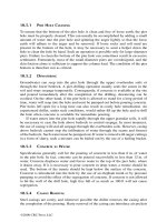
Figure 36.1 illustrates the standard’s framework.
IEEE 1471 provides a key construct that exposes several key terms that serve as the frame-
work for formulating a system, product, or service architecture. Specifically the terms are: archi-
tectural description, viewpoints, views, and concerns.
Simpo PDF Merge and Split Unregistered Version -
36.2 What Is an Architecture? 413
• Architectural Description “An architectural description selects one or more viewpoints
for use. The selection of viewpoints typically will be based on consideration of the stake-
holders to whom the AD is addressed and their concerns.” (Source: IEEE Std. 1471-2000,
para. 4.1, p. 4)
• Viewpoint “A viewpoint establishes the conventions by which a view is created, depicted
and analyzed. In this way, a view conforms to a viewpoint. The viewpoint determines the
languages (including notations, model, or product types) to be used to describe the view, and
any associated modeling methods or analysis techniques to be applied to these representa-
tions of the view. These languages and techniques are used to yield results relevant to the
concerns addressed by the viewpoint.” (Source: IEEE Std. 1471-2000, para. 4.1, p. 4)
• View “A view may consist of one or more architectural models. Each such architectural
model is developed using the methods established by its associated architectural viewpoint.
An architectural model may participate in more than one view.” (Source: IEEE Std. 1471-
2000, para. 4.1, p. 4)
• Concerns “Those interests which pertain to the system’s development, its operation or any
other aspects that are critical or otherwise important to one or more stakeholders. Concerns
include system considerations such as performance, reliability, security, distribution, and
evolvability.” (Source: IEEE Std. 1471-2000, para. 4.1, p. 4)
Attributes of an Architectural Description
An Architectural Description exposes and expresses the architecture of a system, product, or service
via standard attributes and conventions. These include:
Mission
Environment System Architecture
Stakeholder
Concern Viewpoint View
Library
Viewpoint
Model
Architecture
Description
Rationale
fulfills 1 *
influences
inhibits
has an
has 1 *
identifies
1 *
described by
1
provides
participates
in
is important to
1 *
is addressed to
1 *
participates in
1 *
establishes methods for
1 *
aggregates
1 *
has
1 *
identifies
1 *
used to
cover 1 *
has source
0 1
conforms to
selects
1 *
organized by
1 *
Figure 36.1 IEEE-Std-1471-2000 Architectural Description
Source: IEEE-Std-1471-2000 Figure 1: “Conceptual Model of Architectural Description,” p. 5. Reprinted with permission
of IEEE.
Simpo PDF Merge and Split Unregistered Version -
• Architectural Entities An architecture exposes the operational elements such as objects or
actors—which can be persons, places, things, roles, or capabilities—that comprise a
SYSTEM or entity, regardless of the level of abstraction, and interacts synergistically to
perform the entity’s mission.
• Hierarchical Level of Abstraction An architecture expresses an entity’s operational,
behavioral, and physical context within the User’s system of systems (SoS) for a given level
of abstraction (Level 0, Level 1, Level 2, etc.).
• Unique Identity Architecture expresses HOW a SYSTEM’s object or actor capabilities are
uniquely identified via reference designators.
• Interactions with its OPERATING ENVIRONMENT An architecture expresses how the
SYSTEM entity interacts and interoperates with external systems in its OPERATING ENVI-
RONMENT based on external inputs, stimuli, or cues—for example, inputs such as event-
based interrupts, raw materials, and information—as well as its SYSTEM RESPONSES—its
behavioral patterns, products, by-products, or services.
• Completeness An architecture expresses the integrated set of entities, capabilities, and inter-
actions for a specific entity required to satisfy a prescribed set of User mission use cases and
operational scenarios. This is accomplished in terms of incremental or phased capabilities
evolving from: 1) an initial operational capability (IOC) through a series of “builds” to a full
operational capability (FOC) or 2) a single grand design.
• Architectural Views An entity’s architecture is characterized by four types of views: 1) a
requirements view, 2) an operations view, 3) a behavioral view, and 4) a physical view.
Now that we have established WHAT a system architecture is and its attributes, let’s explore the
HOW the architectural description is represented.
Architectural Description Representation Methods
For most applications, system architectures are communicated via three mechanisms: 1) three-
dimensional and two-dimensional artistic renderings of buildings, 2) block diagrams, and 3)
hierarchy trees. Most SE applications employ block diagrams such as system block diagrams
(SBDs), architecture block diagrams (ABDs), and functional block diagrams (FBDs) as the primary
mechanism for communicating a SYSTEM or entity’s architecture.
Block diagrams depict horizontal peer level and external relationships within a given system
level of abstraction. Vertical linkages to higher level parent or lower level siblings are referenced
by symbology but not shown. For example, a system entity, as a level of abstraction, may include
a symbol on or next to its box to denote lower levels exist.
In contrast, hierarchy trees enable us to depict vertical relationships that infer levels of abstrac-
tion; they do not communicate, however, direct relationships and interactions among peers. Figure
36.2 contrats the two approaches.
Architectural Description Views and Concerns
When tasked to develop the architectural description, engineers naturally gravitate to debates over
WHAT tools and methods to use. Traditionally, SEs prefer to use functional methods; software engi-
neers focus on object-oriented methods, and so forth. Instead, the focus should be on WHAT is to
be described in terms of views. Once these views are identified, then you can decide whether a
viewpoint is best described using functional, object-oriented, or some other methods. The selection
depends on WHAT architectural view best communicates the System Architect’s solution to the
User’s vision in a manner that is accepted by the User.
414
Chapter 36 System Architecture Development
Simpo PDF Merge and Split Unregistered Version -
36.3 Architectural Views of a System 415
36.3 ARCHITECTURAL VIEWS OF A SYSTEM
There are numerous engineering perspectives of a system’s architecture. In general, the perspec-
tives are reflective of the views and concerns of key stakeholders of the system, product, or service
as illustrated in Figure 36.3. Your job as a system analyst or SE is to integrate these views.
Earlier we introduced the concept of the four solution domains: Requirements, Operations,
Behavioral, and Physical. Each solution domain represents a unique view of a system representing
a consensus of its stakeholders. Let’s define each view:
• Requirements Architecture View A representation of the hierarchy and traceability of an
entity’s specification requirements that bound its phases and modes of operation, capabili-
ties, characteristics, design and construction constraints, and verification methods.
• Operations Architecture View A representation of HOW the MISSION SYSTEM and
SUPPORT SYSTEM operational assets are employed—meaning deployed, operated, and
supported—by the User in their Level 0 HIGHER ORDER SYSTEM. The operational archi-
tecture may include lower level training, maintenance, and support architectures that graph-
ically represent their respective concepts.
• Logical/Functional Architecture View A representation of the logical/behavioral entity
relationships and interactions—meaning behavior, products, by-products, and services—
that express HOW the MISSION SYSTEM capabilities are envisioned to respond to
external stimuli and cues for hypothesized scenarios within its prescribed OPERATING
ENVIRONMENT.
• Physical Architecture View A representation of HOW an entity is physically composed,
constructed, configured, and interfaced to respond to external stimuli and cues to achieve the
desired outcome-based responses.
2
SYSTEM
SYSTEM
SUBSYSTEM
A
SUBSYSTEM
A
SUBSYSTEM
B
SUBSYSTEM
B
SUBSYSTEM
C
SUBSYSTEM
C
A1
A1
A2
A2
B1
B1
B2
B2
C1
C1
C2
C2
SUBSYSTEM
A
SUBSYSTEM
A
SUBSYSTEM
B
SUBSYSTEM
B
SUBSYSTEM
C
SUBSYSTEM
C
Block Diagram Approach
(Horizontal Architecture Relationships)
Hierarchy Tree Approach
(Vertical Architecture Relationships)
System Architecture
A1
A1
A2
A2
B1
B1
B2
B2
C1
C1
C2
C2
Decomposition
System
SUBSYSTEM A SUBSYSTEM B
SUBSYSTEM C
Figure 36.2 System Architecture Presentation Methods
Simpo PDF Merge and Split Unregistered Version -
416 Chapter 36 System Architecture Development
SYSTEM or Entity
Architectural
Description
SYSTEM or Entity
Architectural
Description
Requirements
Architecture
View
(Multi-Level)
Requirements
Architecture
View
(Multi-Level)
Operations
Architecture
View
(Multi-Level)
Operations
Architecture
View
(Multi-Level)
Logical/
Behavioral
Architecture
View
(Multi-Level)
Logical/
Behavioral
Architecture
View
(Multi-Level)
Physical
Architecture
View
(Multi-Level)
Physical
Architecture
View
(Multi-Level)
Consists of
Requirements
Domain Solution
Operations
Domain Solution
Behavioral
Domain Solution
Physical Domain
Solution
Figure 36.4 System Architectural Description (AD) Elements
Figure 36.4 illustrates these relationships as elements of an overall system architecture description.
The SYSTEM architecture description (AD) consists of a multi-level requirements architecture, a
multi-level operations architecture, a multi-level logical/functional architecture, and a multi-level
physical architecture.
Architectural Responses to the Solution Space
If we translate the IEEE construct shown in Figures 36.1 with the views of a system illustrated in
Figure 36.4, Figure 36.5 results. Here, we see the architectural views as satisfying the solution
space(s) based on stakeholders, views, and concerns.
Guidepost 36.1 At this point we have established the general relationships between the four
solution domain architectures with the solution space. Now let’s explore the interdependencies of
these views further.
System Views
•
Requirements
• Operations
• Behavioral
•Physical
System Views
•
Requirements
• Operations
• Behavioral
•Physical
User(s)
User(s)
Acquirer
Acquirer
System
Engineering
System
Engineering
Hardware
Engineering
Hardware
Engineering
Software
Engineering
Software
Engineering
Specialty
Engineering
Specialty
Engineering
System
Developer(s)
System
Developer(s)
Operator(s)
Operator(s)
Maintainer(s)
Maintainer(s)
System
Administrators
System
Administrators
Instructor(s)
Instructor(s)
= Inputs & Reviews
= Collaboration & Consensus
Where:
Test
Engineering
Test
Engineering
Product
Engineering
Product
Engineering
User Community System Developer
User’s Representative
Figure 36.3 Stakeholder Views of a System
Simpo PDF Merge and Split Unregistered Version -
36.3 Architectural Views of a System 417
Architectural View Interdependencies
The requirements, operations, behavioral, and physical architectures are highly integrated and inter-
dependent shown in Figure 36.6. Notice that the highly iterative interdependencies are depicted via
an N
2
(N ¥ N matrix) diagram. When you develop the architectures, it is very important for you to
maintain traceability with the Contract Statement of Work (CSOW), Contract Work Breakdown
Structure (CWBS), Integrated Master Plan (IMP), and Integrated Master Schedule (IMS) or their
contract documents.
Stakeholder(s)
Stakeholder(s)
SYSTEM or
System
Entity
SYSTEM or
System Entity
Requirements
Architecture
(Multi-Level)
Requirements
Architecture
(Multi-Level)
Operations
Architecture
(Multi-Level)
Operations
Architecture
(Multi-Level)
Behavioral
Architecture
(Multi-Level)
Behavioral
Architecture
(Multi-Level)
Physical
Architecture
(Multi-Level)
Physical
Architecture
(Multi-Level)
consists of
Architectural
Description (AD)
Problem
Spac
e
Solution
Space(s)
View(s
)
View(s)
Concern(s
)
Concern(s)
documented in
documents
captured by
captures
owned by
impacted
by
express
expressed by
partitioned
into
resolve
described by
own
impacts
describes
own
owned by
Figure 36.5 System Solution Viewpoints and Views
6
Requirements
Architecture
(Multi-Level)
Requirements
Architecture
(Multi-Level)
Operations
Architecture
(Multi-Level)
Operations
Architecture
(Multi-Level)
Logical/
Behavioral
Architecture
(Multi-Level)
Logical/
Behavioral
Architecture
(Multi-Level)
Physical
Architecture*
(Multi-Level)
Physical
Architecture*
(Multi-Level)
Requirements Allocation Flow Down
(Capabilities, Characteristics, Design & Construction Constraints, etc.)
•
Phases & Modes
•
Mission Operations
•
Scenarios
•
Event Timelines
•
Budgets & Margins
Requirements
Traceability
Requirements
Traceability
Requirements Traceability
•
Logical Entities
•
Entity Capabilities
•
Behavioral Models
•
Algorithmic Models
•
Budgets & Margins
System or Entity Architecture
* Assembly Drawings, Schematics, Product Structure, Bill of Materials (BOM), Code Listings, etc.
SPS or
Entity Item
Development
Specification
Contract
Statement of
Work
(CSOW)
Contract
Work
Breakdown
Structure
(CWBS)
Integrated
Master Plan
(IMP)/
Schedule
(IMS)
Figure 36.6 System Architecture Element Relationships
Simpo PDF Merge and Split Unregistered Version -
418 Chapter 36 System Architecture Development
Author’s Note 36.1 The point here is that architecture development encompasses more than
simply creating graphical views of the system. The architectural description serves as the corner-
stone for the CWBS, IMP, and IMS. It must also be consistent with the CSOW.
As system development progresses through lower levels of design over time, architectural
attributes such as capabilities or operations, requirements, performance budgets and safety margins,
and design and construction constraints are allocated to lower level architecture entities and flowed
down via entity item development specifications.
Referral For more information about developing specifications, refer to Chapter 31 Specifica-
tion Development Practices.
Closing Points
One of the ambiguities of SE and deficiencies of organizational training or the lack thereof occurs
when system architectures are developed. You may hear a development team member boldly pro-
claim they are going to “develop a system architecture.” The problem is listeners are thinking one
type of architecture and the doer has a “pet” architecture. As a result, the architectural work product
may or may not suit the development team’s needs.
One way to avoid this situation is to express the four domain solutions in terms of views. As
each solution is formulated as illustrated in Figure 36.6, the team has a good idea of WHAT the
deliverable architecture will depict. So, when someone boldly PROCLAIMs to be developing a
system architecture, ASK: WHICH architectural views and viewpoints do you intend to EXPRESS.
Guidepost 36.2 Given a fundamental understanding in WHAT an architecture and architec-
tural description are, we now shift our focus to key considerations that drive selection of the type
of architecture suitable for a system, product, or service application.
36.4 CENTRALIZED VERSUS DECENTRALIZED
CONTROL ARCHITECTURES
Once a system’s interfaces are identified, most system architecture development activities begin
with HOW the system is structured for communications and decision-making. Figure 36.7 serves
as a reference for our discussion.
Chapters 8 through 12 System Architecture Concepts discussed system interactions with its
OPERATING ENVIRONMENT. The discussion highlighted various types of command and control
(C
2
) interactions that included open loop and closed loop systems. For the C
2
mechanism, a key
question is: HOW do we efficiently and effectively implement C
2
? This requires a determination of
the need for a centralized versus decentralized or distributed control architectures. So, what are
these?
Centralized Control Architectures
Centralized control architectures, as illustrated on the LEFT side of Figure 36.7, consist of a single
processing mechanism. For most applications the mechanism interfaces to remote access ports or
sensors via mechanical, electronic, or optical types of devices. Consider the following examples:
Simpo PDF Merge and Split Unregistered Version -
36.4 Centralized Versus Decentralized Control Architectures 419
EXAMPLE 36.1
Video surveillance systems route multi-channel, real-time camera video back to a multi-screen command
center staffed with security personnel.
EXAMPLE 36.2
A power control circuit breaker panel distributes and controls power from an external service line to various
circuits throughout an office building or home.
Limitations of Centralized Control. Centralized control architectures are fine for many appli-
cations such as the examples cited above. However, they do have limitations. They are a potential
single point of failure (SPF).
As a SPF, some applications may require vast lengths of wiring to remote sensors that increase
weight. For applications such as aircraft where an SPF may be a critical risk, additional weight,
assuming it can be accommodated, translates into increased fuel consumption, increased fuel tank
capacity, and reduces payload weight.
There are several approaches to solving this problem space. Example solutions include:
1. AVOID performance degradation and provide for expansion and growth by decentraliza-
tion of processing functions.
2. REDUCE weight by deploying decision-making mechanisms at key locations and inter-
connecting the mechanisms via network-based configuration nodes.
3. AVOID risk due to potential SPFs by implementing control mechanism redundancies.
Centralized Architecture
Command and Control and
Transformational Processing
Decentralized Architecture
Command and Control and
Transformational Processing
Centralized
Control Capability
• Control Capability A
• Control Capability B
• Control Capability C
Centralized
Control Capability
• Control Capability A
• Control Capability B
• Control Capability C
System Service Responses
Control
Capability
A
Control
Capability
A
Control
Capability
B
Control
Capability
B
Control
Capability
C
Control
Capability
C
Supervisory
Control
Capability
Supervisory
Control
Capability
RFS_A #1
RFS_A #x
RFS_B #1
RFS_B #
y
RFS_C #1
RFS_C #z
RFS_A #1
RFS_A #2
RFS_B #1
RFS_B #2
RFS_C #n
Where:
RFS_X = Request for Service A,B, C, etc.
Service A Responses
Service B Responses
Service C Responses
Figure 36.7 Centralized and Decentralized Architectures
Simpo PDF Merge and Split Unregistered Version -
420 Chapter 36 System Architecture Development
Author’s Note 36.2 Based on the SPF discussion, we should note that the processing mecha-
nism, as illustrated at the right side of Figure 36.7, might consist of redundant processors as a
means of improving the mechanism’s reliability.
Decentralized Control Architectures
Decentralized control architectures partition key control functions and deploy them via remote pro-
cessing mechanisms that service input/output (I/O) requests as illustrated at the right side of Figure
36.7. The deployment may require:
1. Remote, dedicated processing to support a specific sensor or suite.
2. Retaining a central supervisory function to oversee each of the decentralized computing
functions.
Depending on the mission and system application, decentralized functions might reside in the same
rack at a site, be physically stationed throughout a building, or geographically separated across a
country or around the world.
The decentralized functions may be allocated to hardware or software entities or dynamically
assigned based on processing loads. As a result, overall system performance is improved but at the
expense and risk of adding more processors. Consider the following example:
EXAMPLE 36.3
An organization operates technical support centers to assist customers in implementing the organization’s prod-
ucts. In one approach, geographic sites are dedicated to addressing specific product questions. Since calls for
a specific product: 1) may not occur in a uniform distribution and 2) may have surge periods, it may be inef-
ficient and unprofitable to employ large staffs at a single site. So, a central phone system places customer calls
in a first-come–first-served queue and assigns each call to “the next available representative or technician”
that may be available in any one of several different product support sites.
For some applications, I/O processors may be identified in an architecture to off-load mundane I/O
processing tasks such as data communications, printing, or interrupts from the main processor. This
allows the supervisory processor to concentrate on higher level performance intensive tasks.
Client-Server Architectures
For system applications that require desktop or Web-based access to a central repository of infor-
mation, client-server architectures are employed. In this case a processor is dedicated to process-
ing client requests for data, retrieving the data from a central repository, and disseminating the data
to the client. Applications such as this, which include internal organizational intranets and Web-
based sites, are helpful for contract programs that need to provide access to program and contrac-
tor data to authorized Acquirer/Users, System Developers, subcontractors, and vendors.
Network Architectures
Organizations and systems often have need for personnel/entities to share and access common
repositories of information as well as e-mail. Because of the cost and risk of having to connect ded-
icated wires from a central C
2
system throughout the facility, high-speed serial data communica-
tions networks are employed. Local Area Networks (LANs) are used to service clients within a
facility, LANs for geographically separated facilities may be connected into wide area networks
(WANs). Consider the following examples:
Simpo PDF Merge and Split Unregistered Version -
36.5 Fault Tolerant Architectures 421
EXAMPLE 36.4
Commercial network systems employ Broadband, DSL, Ethernet, among other data communications. Mili-
tary aircraft on-board networks employ MIL-STD-1553/1773 data communications networks; 1553 for wire-
based applications, 1773 for fiber-optic applications.
36.5 FAULT TOLERANT ARCHITECTURES
The challenge in developing any type of system is creating a system architecture that is sufficiently
ROBUST to tolerate and cope with various types of internal and external vulnerabilities. Then,
when confronted with these conditions, the processing must be able to continue without significant
performance degradation or catastrophic failure.
Depending on system design objectives, there are numerous ways of developing fault-tolerant
architectures. Typically, a failure modes and effects analysis (FMEA) addresses potential failure
modes, system effects, single points of failure (SPF), and so on. A more comprehensive expansion
of a FMEA includes a criticality analysis (FMECA) to identify specific components that require
close attention. The FMEA/FMECA assess and recommend compensating provisions—namely
design modifications and operating procedures to mitigate failure conditions.
Referral A summary of FMEA/FMECA is provided in Chapter 50 System Reliability, Avail-
ability, and Maintainability (RAM) practices.
The FMEA/FMECA, in conjunction with the system’s mission reliability requirement and resource
budgets, influence the system architecture approach. Specification Developers are notorious for
specifying redundancy requirements without thorough analysis of the current system architecture
to determine if redundancy is a necessary and sufficient condition to satisfy mission reliability
requirements. Avoid mandating design methods in specifications that increase cost and risk without
having compelling, fact-based evidence that motivates such actions.
This brings us to a key point: key areas for developing fault tolerant systems.
Key Areas for Developing Fault Tolerant Systems
In general, design flaws and internal component faults or malfunctions can cause or lead to system
failures. Examples include:
1. Inadequate system architecture selection.
2. Lack of system stability during various OPERATING ENVIRONMENT conditions.
3. Internal component failures due to OPERATING ENVIRONMENT conditions, surges, or
long-term effects.
4. Latent defects due to improper or inadequate testing.
5. Faulty control logic.
6. Unknown modes and states.
7. Preoccupation with trivial, molecular level computation processing.
8. Poor work practices.
9. Improper operation results from abuse, misuse, or misapplication of the system or product.
10. Physical breaks in resource or data communications interfaces or supplies.
11. Lack of preventive and corrective maintenance.
Simpo PDF Merge and Split Unregistered Version -
12. Physical intrusion such as hacking, spamming, malicious mischief, and sabotage by unau-
thorized users and threats.
For systems in which a failure may be catastrophic, the system architecture decision making should
include design OPTION considerations such as redundancies. Again, compensating actions should
only be implemented after a determination that design reliability with a SPF is inadequate.
Guidepost 36.3 At this point we have established the commonly used types of system archi-
tectures. We now shift our focus to understanding how to improve the reliability of an architectural
implementation.
36.6 TYPES OF REDUNDANCIES
For most applications we can classify redundancies in terms of architectural configuration and com-
ponent implementation.
Architectural Configuration Redundancy
Architectural configuration redundancy consists of configuring redundant components either as
fully operational “on-line” or “off-line” devices during all or portions of mission phases. There a
three primary types of architectural redundancy: 1) operational, 2) cold or standy, and 3) k out of
n systems.
Operational Redundancy. Operational redundancy configurations employ backup items that
are activated or energized throughout the operating cycle of the system or product. All primary and
redundant elements operate simultaneously for a total of n elements. Some people refer to this as
hot or active redundancy. Consider the following example:
EXAMPLE 36.5
An aircraft may require a minimum number of engines to be operating within specified performance limits
for takeoff, cruising, or landing; independent inertial navigation systems required to continue a mission; or
tandem train locomotives for specific geographic and loading conditions.
During SYSTEM operations, redundant items can also be configured to operate concurrently
and even share the loads. If one of the redundant items fails, the other item(s) assumes the load
performed by the failed item and continues to perform the required capability(s). In most cases, the
failed component is left in place or, assuming it does not interfere or create a safety hazard until
corrective maintenance is available.
Cold or Standby Redundancy. Cold or standby redundancy consists of components that are
not energized, activated, or configured into the system until the primary item fails. If the primary
item fails, the standby item is connected automatically or manually through direct or remote oper-
ator intervention. Consider the following example:
EXAMPLE 36.6
Cold or standby redundancies include an emergency brake on an automobile, adding mass transportation vehi-
cles (trains, buses, etc.) to support surges in consumer demand, emergency backup lighting switched on during
a power failure, and backup power generation equipment.
422 Chapter 36 System Architecture Development
Simpo PDF Merge and Split Unregistered Version -
36.6 Types of Redundancies 423
k-out-of-n Systems Redundancy. This is a hybrid system whereby there are a total of n ele-
ments in the system but only k elements (k out of n) are required to operate during specific phases
of a mission. For example, a car needs four of its five tires, including spare, to be in safe operat-
ing condition to complete a trip.
You may ask: What is the difference between operational redunancy and k-out-of-n redun-
dancy. Operational redundancy assumes all components are configured into the system, can only
be turned on/off, but not easily removed during a mission such as an engine on an aircraft or gyro.
K-out-of-n redundancy factors in spares as replacements such as the car tire example.
Redundancy Implementation Approaches
Once a configuration redundancy concept is selected, the next step is to determine HOW to phys-
ically implement the concept, either by identical components or unlike components that are similar
in function.
Like Redundancy Configuration. Like redundancy is implemented with identical compo-
nents—vendor product model part numbers—that are employed in an operational or standby redun-
dancy configuration.
Unlike Redundancy Configuration. Unlike redundancy consists of components that are not
physically identical—different vendors—but provide the functionality and performance required to
perform the capability.
Both implementation approaches offer advantages and disadvantages. If the components used
for like redundancy are sensitive to certain OPERATING ENVIRONMENT characteristics, having
identical components may not be a solution. If you purposely choose unlike redundancy and the
same situation occurs, redundancy may only exist over a limited operating range if one component
has higher reliability. If components identical only in function and performance are qualified over
the full operating range, unlike redundancy may offer advantages.
Reducing Component SPF Risk
One method of reducing the component SPF risk requires operating identical or redundant com-
ponents in several types of configurations. Redundancy type examples for electronic systems
include:
• Processing redundancy
• Voted k out of n redundancy
• Data link redundancy
• Service request redundancy
Figure 36.8 provides a graphical view to support the discussions that follow.
Processing Redundancy. Returning to an earlier discussion of decentralized processing via dis-
tributed components, detection of a processor failure and dynamic reallocation of processing tasks
to an available processor enhances fault tolerance. So SUBSYSTEMs A and B both include redun-
dant processing components, A¢ and B¢.
Voted “k out of n” Component Redundancy. Some systems have redundant, peer-level
processors that employ an operational hot or active redundancy configuration. Individual processor
results Subsystems A and B are routed through a central decision-making mechanism that determines
if k out of n results agree. If k out of n results agree, transmit the results to a specific destination.
Simpo PDF Merge and Split Unregistered Version -
Data Link Redundancy. There is an old adage: “Systems break at their interfaces.” From an
interface reliability perspective, this adage holds true. System developers often take great pride in
creating ELEGANT system designs that employ redundant processing components. Then, they
connect the redundant components to an external interface that is a single point of failure (SPF).
One way to AVOID this problem is to employ redundant networks as shown in Figure 36.8.
Obviously, if interconnecting components such as cables are placed in a stable/static position, not
subjected to stressful OPERATING ENVIRONMENT conditions, and interfaced properly, there is
a good chance that additional independent connections are unnecessary and can be avoided.
For applications that employ satellite links or transmission lines that may be switched period-
ically, it may be necessary to employ backup links, such as land lines, as a contingency.
Service Request Redundancy. Some systems may be designed to automatically transmit mes-
sages one or more times. Using Figure 36.8 as an example, SUBSYSTEMs A and B automatically
retransmit messages to each other. Others may issue service requests to repeat messages, acknowl-
edgments, or data responses. As illustrated in Figures 15.3 and 15.4, this example is equally appli-
cable to external systems.
36.7 ERROR CORRECTION CONSIDERATIONS
Some systems employ data communication protocols that request retransmission IF errors are
detected. In general, error correction may or may not be considered an explicit redundancy method.
However, when it is employed, it provides comparable benefits.
Guidepost 36.4 The development of a system architecture requires more than simply innova-
tion and creation, it also requires other architectual considerations:
424 Chapter 36 System Architecture Development
Firewall
Firewall
Component
B
HW
SW
Component
B’
HW
SW
Subsystem A Subsystem B
Primary Data Communications Network
Redundant Network
(Option)
Power
Component
A’
HW
SW
Component
A
HW
SW
UPS
(Back-Up)
UPS
(Back-Up)
External
Power
Where:
HW = Hardware
SW = Software
UPS = Universal Power Supply
Figure 36.8 System Architecture Element Relationships
Simpo PDF Merge and Split Unregistered Version -
36.8 Other Architectural Selection Considerations 425
1. Compliance with local, state, federal, and international statutes and regulations.
2. Sustainment of resources.
3. Recognition of the cause and effect the architecture has on the public and the environment.
We now shift the discussion to these considerations.
36.8 OTHER ARCHITECTURAL SELECTION CONSIDERATIONS
Developing a system architecture to provide capabilities to support all phases of the mission is only
part of what is required. The architecture must also include other key considerations. These include:
• Power source architectural considerations.
• Environmental, safety, and health (ES&H) architectural considerations.
• Fire detection and suppression architectural considerations.
• System security architectural considerations.
Power System Architectural Considerations
The preceding discussions highlight HOW to enhance the fault tolerance of the systems and prod-
ucts we build. If they are electrically powered, no matter how elegant the redundancy solution, it
only works WHEN power is applied. The loss of power involves several issues:
1. Safe storage of critical mission and system data immediately following the event to prevent
data loss.
2. Safe evacuation of personnel from facilities to prevent injury or loss of life.
3. Sustainment power to critical processes that must process to completion and place the
system in a SAFE mode.
Sustaining Operations and EQUIPMENT Resulting from Loss of Power. When a power
loss event occurs, systems require a finite amount of time to store mission and system data. To
ensure a continuation of power for a specified time, rechargeable batteries or an uninterruptible
power supply (UPS), offer potential solutions. Depending on mission and system application, alter-
native power solutions include external fuel-based generators, solar panels, fuel cells, and other
technologies.
Power Quality Considerations. Another factor that requires architectural consideration is
power quality. Power surges, brownouts, overvoltage, noise, and stability conditions wreak havoc
with some systems that require power conditioning. So, make sure these considerations are fully
addressed by the architecture within resource constraints.
Environmental, Safety, and Health (ES&H)
Architectural Considerations
System architecting, in general, tends to focus on EQUIPMENT architectures rather than the effects
of the EQUIPMENT on the Users, public, and NATURAL ENVIRONMENT. Therefore, when
evaluating a system architecture, the system architect and others should factor in considerations for
environmental, safety, and health (ES&H).
Simpo PDF Merge and Split Unregistered Version -
426 Chapter 36 System Architecture Development
EXAMPLE 36.7
At a minimum, considerations of the effects of EQUIPMENT by-products on the User(s), public, and envi-
ronment should include the following considerations:
• Moisture
• Condensation
• Water
• Shock and vibration
• Atmospheric pressure
• High pressures
• Noise
• Refuse
• Spills
• Leaks
• Laser radiation
• Nuclear waste
• Ergonomics
EXAMPLE 36.8
At a minimum, safety examples include the following considerations:
• Walk space
• Hazardous conditions
• Ingress and egress
• Emergency exits
• Warning notices and cautions
• Visual and audio alarms
• Electrical shock protection
• Perimeter fencing
• Lockout tags on damaged or out-of-calibration equipment
• Doors and stairwells
• Video surveillance
• Grounding schemes
EXAMPLE 36.9
At a minimum, health examples include the following considerations:
• Toxic chemicals and fumes
• Air quality
• Ergonomics
• Noise
Simpo PDF Merge and Split Unregistered Version -
Fire Detection and Suppression
Architectural Considerations
Another key architectural consideration is fire detection and suppression systems. Since personnel,
equipment, and facility safety are paramount, the system architecture should include features that
enable a rapid response when fires are detected including suppression systems that eliminate the
source of the fire following personnel evacuation.
System Security Architectural Considerations
For those systems that involve sensitive or classified data, system security should be a key archi-
tectural consideration. This includes reasonable measures for physical security, operational secu-
rity, communications security, and data security.
Final Thought
All considered effects should include both the short-term effects and the long-term effects. Com-
pensating actions for any effects may require accomplishment via one or more of the SYSTEM’s
architectural system elements—EQUIPMENT, PERSONNEL, PROCEDURAL DATA, and so
forth.
36.9 GUIDING PRINCIPLES
In summary, the preceding discussions provide the basis with which to establish the guiding prin-
ciples that govern system architecture development practices.
Principle 36.1 An architecture expresses stakeholder concerns via views that comply with
viewpoint conventions for constructing the view.
Principle 36.2 Every SYSTEM/entity has four architectural views: requirements, operations,
behavior, and physical, each consistent with and traceable to the other.
Principle 36.3 System architectural redundancy is a design method for achieving a challenging
reliability requirement, and not a specification requirement.
Principle 36.4 An architecture represents the totality of the integrated configuration of system
capabilities required to perform its use cases and cope with use case scenarios without regard to
element frequency of usage.
Principle 36.5 Every system architecture must be compliant with its specification requirements
and applicable laws, regulations, and cultural values.
Principle 36.6 Every system architecture must factor in considerations for the environment,
safety, and health.
36.10 SUMMARY
The discussion of system architecture development practices of this chapter serve as a precursor for the
Requirements, Operations, Behavioral, and Physical Domain Solutions that follow. System architectures
36.10 Summary
427
Simpo PDF Merge and Split Unregistered Version -
428 Chapter 36 System Architecture Development
provide the means to communicate the key stakeholder concerns and engineering viewpoints required to
develop each SYSTEM or entity’s four solution domains—consisting of Requirements, Operations, Behav-
ioral, and Physical Domain Solutions.
During our discussions we introduced and defined the origin of the term architecture as well as other
architecture-related terms. We discussed the need to delineate the type of system architecture—operational,
behavioral, and physical—when someone boldly proclaims an intent to develop the “system’s” architecture.
Specific architecture view implementations are described in the respective Requirements Domain Solu-
tion, Operations Domain Solution, Behavioral Domain Solution, and Physical Domain Solution practices that
follow.
GENERAL EXERCISES
1. Answer each of the What You Should Learn from This Chapter questions identified in the Introduction.
2. Refer to the list of systems identified in Chapter 2. Based on a selection from the preceding chapter’s
General Exercises or a new system selection, apply your knowledge derived from this chapter’s topical
discussions. Specifically identify the following:
(a) Who are the system’s stakeholders?
(b) What are their views and concerns of the system’s architecture?
(c) How would these views and viewpoint concerns be captured in the Requirements, Operations,
Behavioral, and Physical Domain architectures?
(d) What are potential trade-off areas require consideration in formulating the architecture?
3. Identify an example of each of the types of system architectures and design options listed below:
(a) Centralized architecture
(b) Decentralized architecture
(c) Hot redundancy
(d) Standby redundancy
(e) k out of n redundancy
(f) Like redundancy
(g) Unlike redundancy
ORGANIZATION CENTRIC EXERCISES
1. Research your organizations command media.
(a) What requirements are levied on programs for development of system architectures?
(b) How are system architectures to be evaluated?
2. Contact a small, a medium, and a large contract program in your organization.
(a) What types of system architectures are used?
(b) Does the architecture include redundant elements? Were they required by contract?
(c) Are there redundant elements; what is the rationale?
(d) What compelling evidence—such as meeting reliability, availability, and maintainability (RAM)
requirements—drove them to redundancy?
(e) Was redundancy a requirement in the SPS or development specification? Why?
Simpo PDF Merge and Split Unregistered Version -
Additional Reading 429
REFERENCES
Buede, Dennis M. 2000. The Engineering Design of
Systems. New York: Wiley.
Defense Systems Management College (DSMC). 2001.
Glossary: Defense Acquisition Acronyms and Terms, 10th
ed. Defense Acquisition University Press, Ft. Belvoir, VA.
IEEE 1471-2000. 2000. IEEE Recommended Practice for
Architectural Description of Software-Intensive Systems.
Institute of Electrical and Electronic Engineers (IEEE)
New York, NY.
“Systems always break at their interfaces.” (Anonymous)
ADDITIONAL READING
Leitch, R.D. 1988. BASIC Reliability Engineering Analy-
sis. Stoneham, MA: Butterworth.
Pidd, Michael. 1998. Computer Simulation in Manage-
ment Science, 4th ed. Chichester: Wiley.
Rechtin, Eberhardt. 1991. Systems Architecting: Creat-
ing and Building Complex Systems. Englewood Cliffs,
NJ: Prentice-Hall.
Rechtin, Eberhardt, and Maier, Mark W. 2000. Systems
Architecting: Creating and Building Complex System, 2nd
ed. Boca Raton, FL: CRC Press.
Simpo PDF Merge and Split Unregistered Version -
Chapter 37
Developing an Entity’s
Requirements Domain Solution
37.1 INTRODUCTION
The Requirements Domain Solution bounds an entity’s—SYSTEM, PRODUCT, SUBSYSTEM,
etc.—solution space within technical, technology, support, cost, and schedule constraints and risks.
The Requirements Domain Solution specifies:
1. WHAT capabilities and performance characteristics are required from the system, product,
or service.
2. WHAT levels of performance are expected—and HOW WELL.
3. System element accountability for accomplishing capability-based requirements.
4. WHEN the capability is required.
5. Under WHAT OPERATING ENVIRONMENT conditions and interactions.
6. WHAT outcomes or results are expected to satisfy the User’s operational needs and suc-
cessfully achieve the system and mission objectives.
This chapter expands on the Requirements Domain Solution description introduced in our discus-
sion of the SE Process Model in Chapter 26. Our discussion addresses the Requirements Domain
Solution: objectives, key elements, sequence in the SE Process Model work flow, development
responsibility, dependencies, development methodology, challenges, and work products.
What You Should Learn from This Chapter
1. What is the objective of the Requirements Domain Solution?
2. What are the key elements of the Requirements Domain Solution?
3. What is the relationship of the Requirements Domain Solution to the SE Process Model?
4. Explain the relationships of the Requirements Domain Solution to the Operations, Behav-
ioral, and Physical Domain Solutions?
5. What is the methodology used to develop the Requirements Domain Solution?
6. What are the steps of the methodology employed to derive the Requirements Domain
Solution?
7. How do you develop the Requirements Domain Solution architecture?
System Analysis, Design, and Development, by Charles S. Wasson
Copyright © 2006 by John Wiley & Sons, Inc.
430
Simpo PDF Merge and Split Unregistered Version -
37.1 Introduction 431
8. What are the exit criteria of the Requirements Domain Solution?
9. What are some of the challenges in developing the Requirements Domain Solution?
10. What work products do the Requirements Domain Solution activities produce?
11. How is the Requirements Domain Solution is verified and validated?
Requirements Domain Solution
Development Activity Objective(s)
The objectives of the Requirements Domain Solution development activity are to:
1. Accurately, precisely, consistently, and completely bound the solution space and identify
the required capabilities—the functions and performance, and characteristics required to
satisfy the User’s (contextual role) validated operational need(s).
2. Provide objective evidence as a work product to support entity verification and formal
acceptance.
Author’s Note 37.1 The usage of the term “contextual role” above refers to multi-level devel-
opment. For example, at the SYSTEM Level, the Acquirer and System Developer organizations
establish a contractual agreement for requirements via the System Performance Specification (SPS).
Within the System Developer’s program organization, the System Engineering and Integration Team
(SEIT) establishes item development specifications (IDS) with PRODUCT level integrated product
teams (IPTs), other development teams, or issues subcontracts to develop PRODUCTS. In this latter
context, the SEIT serves as an Acquirer (role) and the IPT, development teams, or subcontractors
serve as System Developers (role) for their respective PRODUCTS.
Key Elements of the Requirements Domain Solution
The key elements of the Requirements Domain Solution and their interrelationships include the fol-
lowing entities: problem space, solution space, operating constraints, capabilities, Mission Event
Timeline (MET), specifications, verification methods, functions, measures of performance (MOP),
critical operational/technical (COIs/CTIs) issues, and clarifications.
Requirements Domain Solution Dependencies
As discussed in earlier sections, the Requirements Domain Solution development is a multi-level,
highly iterative process that requires close collaboration and coordination with the evolving Oper-
ations, Behavioral, and Physical Domain Solutions as shown in Figure 26.3. Iterative analysis and
technical reviews are required, preferably by independent reviewers, to ensure that the SYSTEM
OF INTEREST (SOI) is properly balanced—meaning optimal—from an overall development and
life cycle perspective in terms of technical, cost, schedule, support, and risks.
Requirements Domain Solution Development Sequencing
As the initial stage of SYSTEM and entity development, the Requirements Domain Solution devel-
opment occurs ahead of the Operations, Behavioral, and Physical Domain Solutions as shown in
Figure 23.2. As the technical specification of a contract or task agreement, this solution ultimately
establishes the legal basis for determining formal contract-based acceptance of the physical system,
product, or service by the Acquirer and User.
Simpo PDF Merge and Split Unregistered Version -