Aluminium Design and Construction - Chapter 6 pptx
Bạn đang xem bản rút gọn của tài liệu. Xem và tải ngay bản đầy đủ của tài liệu tại đây (427.63 KB, 24 trang )
CHAPTER 6
Heat-affected zone softening
at welds
6.1 GENERAL DESCRIPTION
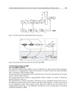
An annoying feature in aluminium construction is the weakening of the
metal around welds, known as HAZ (heat-affected zone) softening (Figure
6.1). With the 6xxx-series alloys, the heat of welding can locally reduce
the parent metal strength by nearly half. With 7xxx alloys, the weakening
is less severe, but extends further out from the weld. For work-hardened
material (5xxx, 3xxx series), the metal in the HAZ becomes locally annealed,
with properties falling to the O-condition level. Only for parent metal
supplied in the annealed or T4 condition can HAZ effects be ignored.
The metal in the HAZ may be weaker than the actual weld metal, or
it may be stronger, depending on the combination of parent and filler
materials used. It often pays to locate welds in regions of low stress, i.e.
away from the extreme fibres or at a section of low moment in a beam.
A full-width transverse weld, as used for the attachment of a web stiffener,
brings a high penalty as it causes softening right across the section.
A designer needs data on two aspects of HAZ softening: its severity
and its extent. The severity is largely a function of the parent material
used, while the extent depends on various factors. The ratio of the area of
affected parent metal (transverse to the weld) to the weld deposit area can
vary from 2 or 3 for a large multi-pass weld to 20 or more for single-pass.
It must be emphasized that the subject of HAZ softening is far from
being an exact science. A well-known method for estimating the extent of
Figure 6.1 Zone of HAZ softening at aluminium welds.
Copyright 1999 by Taylor & Francis Group. All Rights Reserved.
the softening is the famous ‘one-inch rule’ which often proves adequate,
but not always [18]. This simple method is explained in Section 6.5.3,
after which we go on to present a more scientific treatment (RD method),
which may be used to replace the one-inch rule in situations that demand
a more accurate estimate of the HAZ extent (Sections 6.5.4–6.5.11).
Many people think that HAZ softening is such a minor effect that a
very rough estimate of its extent is all that is needed. It is true that with
large multi-pass welds, as used in massive members, the softened area
only extends a short distance in relation to the size of the weld. For
these, almost any extent-rule will usually do. But with smaller welds,
as used in thin members, the extent of the HAZ is relatively much
greater and a better approach is desirable. For these, the one-inch rule
can lead to an estimate of member resistance that is unacceptably low.
The BS.8118 procedure for predicting HAZ extent gets the worst of
both worlds, since it is more awkward to apply than the one-inch rule
and often inaccurate. Our proposed method is more realistic, although
still fairly approximate compared to most structural calculations. In
recent years, special computer programs have become available, which
accurately model the temperature changes during welding and the
resulting metallurgical effect [19]. For a mass-produced component, it
may be sensible to employ one of these. Alternatively, the HAZ pattern
can be found experimentally by making a hardness survey on a prototype.
Designers should also be aware of the locked-in (‘residual’) stresses
in welded components, even though these are not directly considered
in the design process. As with steel, there is a region of locked-in
longitudinal tensile stress at any weld, balanced by compressive stresses
elsewhere in the section. But compared to steel, where the tensile stress
at the weld is invariably up to yield, the stress levels in aluminium are
relatively low. The zone of locked-in longitudinal tension at an aluminium
weld is generally narrower than the HAZ. Mazzolani provides interesting
plots of residual stress in welded aluminium members [26].
Most of this chapter specifically covers HAZ softening at welds
made by the MIG process. TIG welds, for which the HAZ effects are
much less predictable, are considered in Section 6.8. The friction-stir
process is still very new, but some preliminary results suggest that the
softening at FS welds will tend to be less extensive than that at arc
welds (Section 6.9).
6.2 THERMAL CONTROL
The extent of the HAZ can be critically affected by the control of
temperature during fabrication. In a large multi-pass joint, if no such
control were exercised, the temperature of the surrounding metal would
just keep on rising as more passes were laid, leading to a vastly enlarged
Copyright 1999 by Taylor & Francis Group. All Rights Reserved.
area of softening. With 7xxx-type material, it would also increase the
severity of the softening.
What matters is the temperature T
°
of the adjacent parent metal when
any new weld metal is about to be deposited, known as the initial or
interpass temperature. The following effects tend to increase T
°
:
1. The metal is still hot from the welding of a nearby joint.
2. Insufficient cooling time has been allowed since the laying of previous
passes in the same joint.
3. Preheat is used.
4. The ambient temperature is high, as in the tropics.
In order to limit the adverse effects of overheating, an aluminium fabricator
is required to exercise thermal control, namely to ensure that T
°
never
exceeds a specified maximum value. British Standard BS.8118 recognizes
two levels of thermal control, normal and strict, as follows:
All fabrication should satisfy normal control and this is what a designer
would usually specify. With 6xxx or 5xxx-series material, there is often
little advantage in going to strict control, since this affects the area of
softening rather than the severity. There is a stronger case for strict
control with 7xxx, as it also reduces the severity.
When in any doubt, design calculations should be based on normal
control. The assumption of strict control can be justified only in the
following cases:
1. a MIG-welded joint for which strict control is specified, with the
maximum permitted value of T
°
stated to the fabricator;
2. an isolated joint containing one single-pass MIG weld laid without
preheat.
It is obviously advantageous to be able to use the more favourable HAZ
parameters corresponding to strict control, when possible, and it is necessary
to be specific as to which joints can count as case (2). In our treatment
we assume welds to be single-pass up to a size (w) of 8 mm (Section
6.5.5). The definition of an isolated weld is discussed in Section 6.5.10.
6.3 PATTERNS OF SOFTENING
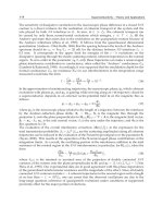
6.3.1 Heat-treated material
Figure 6.2 shows patterns of softening at a single-pass MIG weld, as might
be obtained with 6082-T6 and 7020-T6 material. Such plots are determined
Copyright 1999 by Taylor & Francis Group. All Rights Reserved.
experimentally by conducting a hardness survey, and crudely indicate
the variation in f
u
(ultimate stress) rather than f
o
(proof stress), since
indentation hardness relates primarily to f
u
. The plots in the figure have
not been continued into the actual weld metal, because the strength of
this varies with the filler used.
Two curves are shown for each alloy type, corresponding to welds
made with normal and with strict thermal control. The HAZ can be
divided into two regions (1, 2) as indicated on the plots for normal
control. In region 1, the metal attains solution-treatment temperature
and is thus able to re-age to some extent on cooling. In region 2, this
temperature is not reached, and the metal is over-aged. The hardness
is at a minimum at the boundary between the two regions (point A),
and then rises steadily as we move out to point B. Beyond B, the heat
of welding has negligible effect and full parent properties are assumed
to apply. In region 1, the hardness increases as we move in towards the
weld, although only slightly so for 6xxx material.
It is seen that the use of strict thermal control considerably reduces the
extent of the softening for both alloy types. With 7xxx material, it also
improves the properties in region 1 and reduces the amount of drop at
A. With 6xxx material, the effect of thermal control on severity of softening
is only slight. Very roughly, the relative widths of the two regions (1, 2)
in Figure 6.2 satisfy the expressions below, where x
A
and x
B
are the distances
of A and B from the middle of the weld (applicable to MIG welds):
6xxx series x
A
0.5x
B
(6.1a)
7xxx series x
A
0.8x
B
(6.1b)
6.3.2 Work-hardened material
With the non-heat-treatable alloys, HAZ softening need only be consid-
ered for work-hardened material; it is not a factor with extrusions or
Figure 6.2 Typical hardness plots at a weld in heat-treated aluminium.
Copyright 1999 by Taylor & Francis Group. All Rights Reserved.
annealed plate. Figure 6.3 shows the pattern of softening that might be
obtained at a single-pass MIG weld on 5083-H22 material. Again, regions
1 and 2 can be identified. In region 1, the hardness is now uniform and
corresponds to the properties of the alloy in the annealed condition. As
with the 6xxx series, the use of strict thermal control reduces the extent
of the softening, but does not improve the strength in the HAZ. The
relative widths of the two regions at a MIG weld are roughly given by:
5xxx series x
A
0.3x
B
(6.1c)
A generally similar pattern would be obtained for 3xxx-series material,
but possibly with a different width of softened area. Data on 3xxx
materials are not generally available.
6.3.3 Stress-strain curve of HAZ material
Figure 6.4 compares typical stress-strain curves that might be obtained
using coupons from the HAZ and from the parent metal. It is seen that the
Figure 6.3 Typical hardness plots at a weld in work-hardened aluminium.
Figure 6.4 Parent and HAZ stress-strain curves compared (6082-T6).
Copyright 1999 by Taylor & Francis Group. All Rights Reserved.
HAZ curve has a more rounded knee, with a lower proof/ultimate ratio.
Plots such as those in Figures 6.2 and 6.3, based on hardness surveys,
give a visual picture of how the ultimate stress (f
u
) is reduced in the
HAZ. The drop in proof stress will be more marked. This is especially so
for non-heat-treatable material (5xxx series) supplied in a hard temper.
6.3.4 Multi-pass welds
Figure 6.5 shows the typical softened zone at a large multi-pass weld.
Regions 1 and 2 can again be identified, analogous to those shown in
Figures 6.2 and 6.3 for a single-pass weld, now extending uniformly
around the edge of the deposit. As we move away from the weld, the
strength varies in the same general way as before, the lines A and B
being metallurgically equivalent to points A and B in Figure 6.2 or 6.3.
6.3.5 Recovery time
With work-hardened alloys, the final HAZ properties are reached as soon
as the metal has cooled after welding. But, with heat-treated material, the
immediate strength in the HAZ is low, the final HAZ properties only
being developed after enough time has elapsed to allow natural ageing to
occur. Providing the component is held at a temperature of at least 10°C
after fabrication, this time (the recovery time) may be roughly taken as:
6xxx-series alloys 3 days
7xxx-series alloys 30 days
If heat-treated material is held significantly below 10°C, the recovery
time will be longer. On the other hand, quicker recovery can be achieved
by post-weld artificial ageing. This involves holding the welded component
at a temperature between 100 and 180°C for up to 24 hours, the exact
procedure depending on the alloy. Such treatment also has a strengthening
effect.
Figure 6.5 Pattern of softening at multi-pass weld on thick material.
Copyright 1999 by Taylor & Francis Group. All Rights Reserved.
6.4 SEVERITY OF HAZ SOFTENING
6.4.1 Softening factor
The severity of softening in the HAZ is expressed in terms of a softening
factor k
z
which is intended to represent the ratio of HAZ strength to
parent metal strength. At the current state of the art, it is only possible
to suggest approximate values for this factor. Typically HAZ experiments
employ hardness surveys, and although these give a good indication of
the extent of the softened zone, they say much less about the actual
tensile properties of the softened metal, because the hardness number
correlates only crudely with tensile strength and hardly at all with
proof stress. Also, there tends to be a lot of scatter between specimens.
In fact, for any given material we recognize three different values for
kz (as in BS.8118), and Section 6.6 explains which value to use when.
k
z1
This value is used for calculations involving the limiting stress
p
a
(Table 5.2). Because p
a
=0.5(f
o
+f
u
), the factor k
z1
is notionally
intended to represent the ratio of the HAZ value of this quantity
to that for the parent metal, averaged over the width of region
1 (Figure 6.2).
k
z2
This value is employed for resistance calculations that involve the
limiting stress p
o
. Because p
o
is normally equal to the proof stress f
o
,
we (notionally) take k
z2
as the ratio of HAZ proof to parent metal
proof, again averaged over the width of region 1. The fact that the
HAZ material has a lower proof/ultimate ratio than that for the
parent metal (Figure 6.4) means that k
z2
<k
z1.
k
z3
This is a value which must be used for joint design in 7xxx material,
when tensile stress acts transverse to the axis of the weld. It allows
for the dip in HAZ properties at point A (Figure 6.2) and is notionally
taken as the ratio of the quantity 0.5 (f
o
+f
u
) at this point to its value
for the parent metal. With 6xxx material and also non-heat-treatable
material there is negligible dip at A, and k
z3
=k
z1
.
6.4.2 Heat-treated material
Table 6.1 lists proposed k
z
-values for MIG-welded joints in 6xxx and
7xxx-series alloys. These have generally been pitched higher than the
corresponding BS.8118 values, in line with current European thinking
[20]. The 6xxx values are mainly based on results from specimens in the
6082 alloy, which are assumed to apply to any 6xxx material. Whether
this is a valid assumption for the weaker kind of 6xxx alloy (such as
6063) is by no means clear.
Copyright 1999 by Taylor & Francis Group. All Rights Reserved.
6.4.3 Work-hardened material
For work-hardened material, it may be assumed that the material in
region 1 of the HAZ has the same properties as those for annealed material
(Figure 6.3). Also, there is no dip at point A. The softening factor may
therefore be taken as follows:
(6.2a)
(6.2b)
where f
o
,
,
f
u
are the 0.2% proof stress and tensile strength of parent metal,
and f
oo
, f
uo
are the same in the annealed condition.
6.5 EXTENT OF THE SOFTENED ZONE
6.5.1 General considerations
In the design of joints, one only needs to know the severity of softening
in the HAZ. In member design, one must also know its extent, so that
the total softened area at any critical cross-section can be determined.
In discussing HAZ extent, two broad categories of welded joint may be
recognized (Figure 6.6):
1. long straight joints, comprising one or more welds, as used for
assembling a fabricated member from its component parts;
2. irregular attachment welds, as used for connections between members,
or for securing local attachments, such as lugs, stiffeners, brackets, etc.
In massive members with multi-pass welds, category 1 joints cause softening
in only a small proportion of the total section, and have a minor effect
on the resistance. For these, a very approximate estimate of the HAZ
extent is acceptable. But for small members, containing single-pass welds,
Table 6.1 HAZ softening factor for heat-treated material at MIG-welded joints
Note. *The second row of values of 7xxx-series material in the T6 temper (shown in brackets) may be used
when strict thermal control is exercised during welding (see Section 6.2).
Copyright 1999 by Taylor & Francis Group. All Rights Reserved.
the area of softening is relatively much greater and a more realistic
estimate may be needed. Category 2 joints often extend over a large
part of a member’s width, causing a major proportion of the cross-
section to become softened (or all of it).
The well-known method for estimating the extent of the HAZ is the
one-inch rule [18]. Though crude, it is an invaluable design tool. We
believe that a sensible strategy is to employ the one-inch rule for all
preliminary calculations, with the option of switching to a more scientific
method for the final check. In many cases it will be found that the effect
of the HAZ on the resistance of the section is small, making the use of
the one-inch rule quite acceptable. But in other cases, where preliminary
calculations show that HAZ softening reduces the resistance significantly,
worthwhile economies can be made by the use of a more refined treatment
for the final design. In Sections 6.5.4–6.5.11, we present such a treatment,
based on the work of Robertson at Cambridge during the 1980s [21],
which leant heavily on the classic heat-flow equations of Rosenthal
(Figure 6.7). We call this the ‘RD method’ [22].
Figure 6.6 Categories of welded joint for estimation of HAZ extent: (1) long straight joints;
(2) attachment weld.
Figure 6.7 Heat-flow cases analysed by Rosenthal (moving heat source).
Copyright 1999 by Taylor & Francis Group. All Rights Reserved.
6.5.2 Nominal HAZ
In performing resistance calculations for welded members, the accepted
practice is to use a nominal HAZ as an approximation to the true pattern
of softening. In this, a weakened region of uniform strength is assumed
adjacent to the weld, beyond which a step-change occurs to full parent
strength.
Figure 6.8 illustrates the nominal pattern for joints in thin plate, with
the step-change occurring at C, midway between the points A and B in
the true pattern. A similar principle applies to joints in thick plate, with
an assumed zone of uniform softening bounded by a line C (Figure 6.9).
6.5.3 One-inch rule
The one-inch rule was devised by Hill, Clark and Brungraber of Alcoa,
and has been widely used since the 1960s. It simply states that the
nominal HAZ extends a distance 1 inch (25 mm) in every direction
from an appropriate reference point in the weld. For an in-line butt, the
reference position is the centre-line of the weld (Figure 6.10(a)), while
for a fillet it is at the root (6.10(b)).
With fillet welds on thick plate, the one-inch rule officially allows the
HAZ boundary to be taken as an arc, as indicated in Figure 6.10(c). We
believe this to be an unnecessary refinement that negates the simplicity of
the rule, and instead would recommend the use of a square corner (as also
Figure 6.8 Extent (CC) of nominal HAZ for thin plate.
Figure 6.9 Extent of nominal HAZ (line C) for thick plate.
Copyright 1999 by Taylor & Francis Group. All Rights Reserved.
shown). This makes for simpler calculations, the difference being small
when compared to the overall degree of approximation in the method.
6.5.4 RD method
The one-inch rule is a brilliant simplification of a complex problem.
Most of the time it works well and leads to acceptable predictions for
the resistance of a welded member. But there are some situations where
a lot of the cross-section gets softened, leading to a pronounced drop
in resistance compared to the non-softened value. For these the one-
inch rule can seriously exaggerate the extent of the HAZ, and hence
significantly underestimate the performance of the member. In such
cases, although the one-inch rule is convenient for use in preliminary
calculations, it is clearly desirable to turn to a more scientific treatment
for the final design [21, 22].
Below (Sections 6.5.5–6.5.11) we present such a treatment, referred to
as our ‘RD method’. This assumes that the nominal HAZ extends a distance
s away from the weld deposit in every direction (Figure 6.11), where s is
a function of weld size, alloy type and thermal control. In thin material,
the boundary of the HAZ is taken straight across the thickness, as shown,
In thick plate, when the HAZ only penetrates part way through, we take
square corners instead of arcs for the sake of simplicity.
6.5.5 Weld geometry
For the purpose of our RD method, it is necessary to know the effective
weld size w, and Figure 6.11 shows how we define this for some typical
weld geometries. For any of these the relation between deposit area
and weld size may be approximately taken as:
A
w
=0.7w
2
(6.3)
Figure 6.10 One-inch rule, extent of nominal HAZ.
Copyright 1999 by Taylor & Francis Group. All Rights Reserved.
where A
w
is the deposit cross-section, namely the actual added area
including reinforcement or convexity. For other geometries, or preparation
angles, the effective weld size w should be taken thus:
(6.4)
where A
w
includes a realistic allowance for convexity of the weld profile.
If, at the design stage, the weld has not yet been detailed, w must be
estimated from a knowledge of the plate thicknesses, a liberal value
being assumed so as not to underestimate the HAZ.
With small welds, it is easy for the welder to lay a larger deposit than
that shown on the drawing, leading to an increased area of HAZ. This can
Figure 6.11 RD method, assumed HAZ geometries.
Copyright 1999 by Taylor & Francis Group. All Rights Reserved.
be allowed for in design by replacing the specified weld size w by a
modified value w
1
obtained thus:
w
1
=lesser of aw and 8 mm (6.5)
where is an oversize factor. The factor should typically lie in the
range 1.0–1.1 for butt welds and 1.0–1.2 for fillets, depending on the
standard of deposit control exercised in fabrication. The HAZ at a small
weld can grow by 40 or 50% with an over-enthusiastic welder.
We assume that MIG welds will be single-pass up to w=8 mm,
corresponding to A
w
=45mm
2
. Beyond this they are treated as multi-
pass welds. Also, our treatment assumes that for large welds the deposit
area per pass is 45 mm
2
. In practice, the maximum deposit area per
pass is usually less than this, perhaps 40 mm
2
, and our assumptions are
therefore slightly pessimistic in that they tend to overestimate the extent
of the HAZ.
6.5.6 Single straight MIG weld
First we consider the basic case of a long straight MIG-welded joint
containing a single weld (Section 6.5.1, category 1). Our method is an
attempt to rationalize Robertson and Dwight’s results [21], three ranges
of weld size being recognized: small, medium, big. The rules for small
and big welds are closely based on Robertson’s research, while for the
medium range we employ an empirical procedure to bridge the gap.
It is found that a radically different approach is needed for small welds,
as compared with big ones [22]. With small welds, the operative quantity
is the area of the HAZ, this being a simple multiple of the area of the
deposit. For such welds, therefore, the dimension s increases with size of
weld; also, it varies according to the number of heat-paths away from the
weld. In contrast, at big welds, s is unaffected by weld size or joint geometry.
1. Small welds (w 8mm). In this range it is assumed that the weld is
single pass, and that Rosenthal’s two-dimensional case is relevant
(Figure 6.7). The area of the HAZ is found directly as follows:
(6.6)
where: A
z
=section area of nominal HAZ,
A
w
=actual section area of weld deposit (added area),
w
1
=modified weld size (equation 6.5),
K=factor to be read from Table 6.2.
The actual distribution of the HAZ material can then (if necessary) be
found by determining s so as to bring A
z
to the value obtained above.
2. Medium welds (8<w<20 mm). Two estimates are made using the
empirical rules P and Q, and the less favourable then taken:
Copyright 1999 by Taylor & Francis Group. All Rights Reserved.
Rule P: A
z
is put equal to the relevant value in Table 6.2, namely
that which equation (6.6) would give when w=w
1
=8 mm.
Rule Q: Dimension s is taken equal to the appropriate value in Table
6.2 (proportional to the weld size).
3. Big welds (w 20 mm). The reasoning in this range is that each pass
has a ‘zone of influence’ as typically shown in Figure 6.12, which can
be related to Rosenthal’s three-dimensional heat-flow case (Figure
6.7). The radius s of this zone depends on the alloy type and the
level of thermal control. Table 6.2 gives proposed values of s
pessimistically based on a deposit size of 45 mm
2
per pass. The nominal
extent of the overall HAZ is constructed by taking the envelope of
the zones of influence for all the passes. This is achieved by drawing
a series of lines, as shown, each distant s from the relevant welded
surface, arcs being replaced by square corners.
Table 6.2 HAZ-extent parameters for a single straight MIG weld
Figure 6.12 Assumed extent of nominal HAZ at a large multi-pass weld, showing ‘zone of
influence’ for one of the passes.
Copyright 1999 by Taylor & Francis Group. All Rights Reserved.
6.5.7 Variation of HAZ-extent with weld size
The upper plot in Figure 6.13 shows how the area A
z
of the nominal
HAZ, as predicted in Section 6.5.6, varies with size for a long straight
fillet weld (MIG) of typical geometry at a joint in 6xxx-series plate.
Two curves (N, S) are plotted, corresponding to normal and strict
thermal control. On curve N, a hatched area appears in the region t
< 8 mm to indicate how A
z
is affected by deposit control ( =1.0–1.2,
see Section 6.5.5). For curve S, which relates to strict thermal control,
it is assumed that the deposit control would also be strict ( =1). Note
that, when t < 8 mm, curve S is valid even if strict thermal control has
not been specified, provided the joint is far enough away from other
joints to count as ‘isolated’.
Comment is needed on the fact that there is a region on each curve in
which A
z
is shown constant and not going up with weld size. Referring
to either curve, the point defined by t (= w) =8 mm represents the largest
Figure 6.13 Predicted area (A
z
) of nominal HAZ, comparison of RD method and one-inch
rule. RD method: N=normal thermal control; S=strict thermal control. One-inch rule: curve
1 assumes arcs; curve 2 assumes square corners.
Copyright 1999 by Taylor & Francis Group. All Rights Reserved.
size of single-pass weld. A slightly bigger weld (say w=9 or 10 mm)
will be laid in two passes and have a smaller softened area than that
for a single-pass weld with w=8 mm. This is because the deposit area
per pass will be less than for the 8 mm weld, coupled with the fact that
there will be a high degree of overlap between the zones of influence
for the two passes. The true plot of A
z
versus weld size therefore dips
suddenly at w=8 mm and then climbs, as illustrated in Figure 6.14
(broken line). This would be hard to codify, and for design we
conservatively draw a horizontal line as shown (rule P).
The estimated area of nominal HAZ for welds on 5xxx-series material
was shown by Shercliff [23] to be the same as that for 6xxx, even though
the actual pattern of softening is different. The 6xxx curves therefore
apply to 5xxx series too.
Figure 6.13 also includes equivalent curves for welds on 7xxx-series
material. It is seen that A
z
is generally higher than for 6xxx material,
the 7xxx-series S-curve coinciding with the 6xxx-series N-curve.
Included in Figure 6.13 are curves obtained by applying the one-inch
rule to this geometry. It is seen that, for smaller welds (say w=4–15
mm), the one-inch rule can seriously overestimate the HAZ-extent for
5xxx and 6xxx material, but gives a more reasonable answer for 7xxx
material. At the worst, the one-inch predictions for welds on 6xxx material
are too high by a factor of 2.5 or 3. This is the range where reasonable
accuracy is most desirable. For big welds (w > 20 mm), the one-inch
rule overestimates A
z
for 6xxx material and gets it about right for 7xxx
material. However, in this range a very approximate answer is acceptable.
6.5.8 Overlapping HAZs
It often happens that the individual HAZs due to two different welds
overlap, thus producing a single softened zone (Figure 6.15). This occurs
in a multi-weld joint, and also when two joints are near together. The
combined HAZ for the two welds is found by plotting the extent of the
Figure 6.14 Variation in A
z
for weld sizes around w=8 mm for the joint geometry in
Figure 6.13.
Copyright 1999 by Taylor & Francis Group. All Rights Reserved.
nominal HAZ for each in turn, using the appropriate dimension s for
each weld treated on its own, and then taking the enclosed area. The
overlap area is counted just once.
This procedure will no longer be valid when simultaneous deposits
are laid in the two welds, using a twin-torch technique. This may lead
to a greatly increased HAZ.
6.5.9 Attachment welds
The basic method in Section 6.5.6 was developed from a study of long
straight welds. The case of localized ‘attachment welds’ (Section 6.5.1,
category 2) is more difficult.
Referring to Figure 6.16, the aim is to find the area of the HAZ
material at a critical cross-section of the main member. This extends the
full width of the connected part plus a projection s at each side, or up
to a free edge if this is nearer. The HAZ penetrates a distance s into the
main member, or the full thickness t if this is less. If the weld passes
close to a corner of the section, the HAZ extends around the corner to
give the same total area of HAZ. When the weld is circumferential, as
in the attachment of a tubular branch member, the HAZ should be
taken as extending right across the enclosed region.
Figure 6.15 Overlapping HAZs.
Figure 6.16 Nominal HAZ at an attachment weld.
Copyright 1999 by Taylor & Francis Group. All Rights Reserved.
The problem is to decide on a suitable value of the parameter s for
such welds. An instinctive procedure might be to consider a section
transverse to the axis of the weld, and determine s in the same way as
for a long straight joint of the same geometry, using the data in Table
6.2. This is not acceptable. In practice, the whole of an attachment
weld, or all of one pass, will be laid non-stop without pause. The resulting
heat flow, which is complex, would have to be determined on a one-off
basis using a specialist computer program or else experimentally, neither
of which may be practicable. The only sure thing is that the heat flow,
and hence the pattern of softening, will be more unfavourable than that
based on a straight weld.
The designer, therefore, should first calculate the value of s for an
equivalent long straight weld of the same size, and then increase this
by a suitable factor to allow for all the imponderables. For lack of hard
data, we would suggest an arbitrary increase of 25% in the value of s,
although this may be pessimistic when applied to a very short attachment
weld (connection of a small lug, say).
With a wide attachment, the precise amount that the HAZ projects
at either side is relatively unimportant, since it forms only a small part
of the total affected width. The penetration into the thickness is more
critical. If a small attachment weld is used on a relatively thick member,
the HAZ penetrates only part way into the thickness, leading to a much
smaller area of HAZ than that based on full penetration such as would
be predicted by the one-inch rule.
6.5.10 Definition of an isolated weld (10A-rule)
For an isolated single-pass weld, it is permissible to use the more favourable
HAZ parameters based on strict thermal control, even when only normal
control is specified. How do we define ‘isolated’? The following ‘10A-
rule’ for so doing is derived from Rosenthal’s heat-flow equations [22].
Referring to Figure 6.17, weld Y may count as isolated provided that:
A
p
10A
zp
(6.7)
where A
p
=cross-section area of plate on the heat-path from any
neighbouring weld (X) to the weld considered (Y), as measured from
the nearest point in each weld, and A
zp
=section area of that part of the
nominal HAZ at weld X that lies in the interconnecting plate, measured
from the nearest point in weld X.
Figure 6.17 Check for an isolated weld, ‘10A-rule’.
Copyright 1999 by Taylor & Francis Group. All Rights Reserved.
In determining A
zp
, an appropriate level of thermal control should be
assumed for weld X. When a member contains just two welds, both
may count as if welded under strict control, provided equation (6.7) is
satisfied and both are single-pass.
6.5.11 RD method, summary
The procedures described in Sections 6.5.4–6.5.10 are summarized below.
They enable the area and extent of the nominal HAZ (Section 6.5.2) to
be found at any given cross-section in a member, adjacent to a MIG-
welded joint.
1. Decide on the weld size w, or the modified value w
1
in the case of a
small weld (Section 6.5.5), or estimate w from the plate thickness.
2. Decide on the effective level of thermal control (normal or strict)
(Section 6.2 and 6.5.10).
3. Decide whether the joint is category 1 (long straight) or category 2
(attachment weld), see Section 6.5.1.
4. Category 1 joint containing a single MIG weld. Figure 6.11 shows
assumed shape of nominal HAZ, defined by parameter s. Section
6.5.6 explains how to find s, using Table 6.2.
5. Category 1 joint containing two or more MIG welds. Obtain s as in 4
for each weld treated on its own, and then proceed as in Figure 6.15.
(Section 6.5.8).
6. Category 2 joint. Base the nominal HAZ on a value of s which is 25%
higher than that for a category 1 joint having the same weld section
geometry. See Section 6.5.9.
6.6 APPLICATION OF HAZ DATA TO DESIGN
6.6.1 Design of members
Some members are welded in such a way as to cause total softening at
a particular cross-section, as for example at the end connection of a
tubular member in a welded truss, or where transverse stiffeners are
welded to an I-beam. In such cases, the resistance of the cross-section
is simply found by making a conventional calculation, but using the
appropriate limiting stress (k
z
p) in place of the parent value (p).
Such a calculation would be pessimistic if applied to cross-sections
that are only partially softened, as it would leave the non-softened
material understressed. Instead, the accepted practice for these is to
take an effective section, in which HAZ softening is allowed for by notionally
removing some of the area locally around each weld. The resistance is
then based on the effective section, instead of the actual one, assuming
it to be entirely composed of full strength (unsoftened) material.
Copyright 1999 by Taylor & Francis Group. All Rights Reserved.
The effective section is obtained by replacing the area A
z
of the
nominal HAZ in each softened region by an effective area k
z
A
z
. The
effective section properties may then be found by one or other of the
following methods (refer also to Sections 10.2.4, 10.3.4):
1. Method 1. An effective plate thickness of k
z
t is generally assumed in
each nominal HAZ region, instead of the true thickness t. In thick
material, such that the nominal HAZ penetration s is less than t, the
effective thickness is taken equal to {t-s(1-k
z
)}. The properties of the
effective section thus obtained are then determined in the usual way.
2. Method 2. The section properties are first calculated with HAZ softening
ignored, and suitable deductions then made corresponding to a ‘lost
area’ of A
z
(1–k
z
) at each HAZ.
Method 2 is generally preferred for members just containing small
longitudinal welds, since it only involves A
z
which is readily found
(equation (6.6)), without the need to know the exact location of the
softened metal.
For any given material there are in general three possible k
z
-values
(see Section 6.4.1). The first two of these are needed for member design
and are selected as follows:
k
z1
shear force resistance in beams (Section 8.3);
local failure in tension and compression members (Section 9.3).
k
z2
moment resistance in beams (Section 8.2);
general yielding in tension members (Section 9.4);
overall buckling (Sections 8.7.4, 9.5, 9.6).
In service, the strains arising in the softened zones at a partially welded
cross-section are the same as those in the adjacent unsoftened material.
With the above method of calculation therefore, using an effective section,
the HAZ material will yield prematurely—well before the calculated
resistance of the member is reached, and possibly even at working
load. Some inelastic deflection therefore takes place, leading to a slight
permanent set after the first loading. This does not matter, since the
component will behave elastically under further load applications, and
the inelastic deflection is small. (A similar state of affairs exists with
steel members, where premature yielding occurs in parts of a section
due to the very considerable locked-in stresses present in all steel
components—much worse than in aluminium.)
6.6.2 Design of joints
In determining the resistance of a load transmitting joint, two calculations
are generally needed: one for failure of the actual weld metal, and one
for failure in the fusion zone—see Section 11.3. The latter refers to a
Copyright 1999 by Taylor & Francis Group. All Rights Reserved.
failure plane in the HAZ, close to the weld deposit, for which the
limiting stress is taken as the basic parent value factored by k
z1
.
With welds in 7xxx material, carrying transverse tension, a check is
also needed for possible failure at the dip in HAZ (point A in figure 6.2).
For this we take k
z
=k
z3
.
6.7 COMPARISON WITH ONE-INCH RULE
It has already been stated that the most useful HAZ treatment for general
use in design is the simple, but conservative, one-inch rule. In many
situations, the softened region is relatively small and any slight over-
estimate of its extent, through employing the one-inch rule, is justified
by the simplicity. But there are other cases where HAZ effects cause a
more serious drop in the resistance of a member, perhaps 10 or 20%.
For these, the one-inch rule becomes too pessimistic, and something
better is then needed if an economic section is to be arrived at. Our RD
method is proposed as a more scientific alternative.
Figure 6.18 shows two beam sections for which relevant parameters
are as follows:
Alloy 6082-T6
Welding process MIG
Limiting stress p
o
260 N/mm
2
Softening factor k
z
0.60.
Included against each section is a bar-chart showing how the ratio M
c
/M
cg
varies, depending on which HAZ method is used, where M
c
=calculated
Figure 6.18 Effect of HAZ softening on calculated resistance for two members in bending.
Comparison of proposed RD method and the one-inch rule. RD method: N=normal thermal
control; S=strict thermal control.
Copyright 1999 by Taylor & Francis Group. All Rights Reserved.
moment resistance with softening allowed for, and M
cg
=moment resistance
based on gross section properties (HAZ effects ignored).
Section 1 is a conventional plate-girder, with a 5 mm web that is just
semi-compact. In applying the RD method, we cover two possibilities S
and N as follows:
S Strict thermal control, with strict deposit control ( =1.0);
N Normal thermal control, and a more liberal deposit control
( =1.2).
The predicted fall in resistance below the unsoftened value is as follows:
RD method: S 8%;
N 16%;
One-inch rule: 23%.
It is worth noting that strict control (S) is quite realistic for a section
such as this. With the welding sequence shown, it is only necessary for
strict control to allow cooling between welds 2 and 3 (i.e. when the job
is turned over to weld the second side). The 10A-rule shows that there
is no need for a cooling pause after weld 1 or 3.
Section 2 is a large extruded box-section with square pads welded on
top and bottom, the member being bent about its minor axis. The HAZ
effect is considerable, because a large proportion of the top and bottom
flanges is softened. In applying the RD method, we again cover strict
and normal thermal control (S, N), and in so doing include the 25%
increase in s due to the welds being category 2 (attachment welds). Deposit
control is not an issue, because the weld size is the maximum for single-
pass. The predicted losses in resistance due to HAZ effects are as follows:
RD method: S 19%;
N 23%;
One-inch rule 34%.
Even when strict thermal control is not specified, the S-value will still
be generally valid, because the welds are far enough apart to count as
‘isolated’ when the 10A-rule is applied. This would only cease to apply
if preheat were used, or there was other welding nearby.
6.8 HAZ AT TIG WELDS
6.8.1 Difference between TIG and MIG welding
The data provided in this chapter have so far assumed the use of the
MIG-welding process. When TIG welding is used, a common choice for
small welds, the situation changes.
Copyright 1999 by Taylor & Francis Group. All Rights Reserved.
With MIG welding, an electrode-positive DC process, a steady two-
thirds of the heat input to the arc is used in melting off electrode wire,
while the other third is released at the weld pool. The total heat input
therefore, and hence the extent of the HAZ, is proportional to the size
of the weld deposit. This forms the basis of equation (6.6). With TIG
welding, an AC process, the total arc energy is about equally shared
between the tungsten electrode and the weld pool. The heat released at
the weld pool is thus half the total energy input. However, only part of
this goes into the (hand-held) filler wire and the amount available for
melting off this latter is less than half the total, perhaps only a third or
a quarter, as compared with two-thirds for the MIG process. For a
given size of deposit (equal to the amount of filler consumed), the
extent of the HAZ (a function of the total energy) is therefore considerably
greater for TIG than it is for MIG welding.
A further factor is that the TIG process is more dependent on the
operator’s technique, as compared with the semi-automatic MIG process.
If the torch is allowed to dwell, the heat input per unit length of weld
goes up, causing the extent of the HAZ to increase still further locally.
The result is that the HAZ extent at a TIG weld is (a) greater than for
a MIG weld having the same deposit size, and (b) variable.
Unfortunately, no systematic study appears to have been made of
HAZ effects at TIG welds, and we only have a limited number of hardness
surveys to refer to. These confirm that the extent of the softening is
much more than with MIG. More information is needed.
6.8.2 Severity of softening with TIG welding
With non-heat-treatable material (3xxx, 5xxx series), it is reasonable to
assume that the use of TIG welding will not increase the severity of
HAZ softening, only its extent. Therefore, the k
z
-values given in Section
6.4.3 remain valid.
With 6xxx-series material, we have seen that the severity of softening
for MIG welds is only slightly affected by the level of thermal control,
and one may reasonably infer that the values in Table 6.1 could also be
used with TIG welding. Data from a very limited range of test results,
however, have been interpreted as showing that such a view is optimistic
and that lower k
z
-values should be taken.
With 7xxx-series material, it is known that the severity of softening,
especially the dip at the point of minimum strength (Figure 6.2), is
significantly more pronounced with normal thermal control than it is
with strict. This suggests that with the increased heat input of TIG the
softening will be definitely more severe.
Summarizing, we would at present recommend that k
z
-values be taken
as follows when welds are made by TIG:
Copyright 1999 by Taylor & Francis Group. All Rights Reserved.
3xxx, 5xxx same as for MIG;
6xxx reduce MIG value by 0.05;
7xxx reduce MIG value by 0.2.
6.8.3 Extent of the softened zone for TIG welding
With the present dearth of information, we would tentatively suggest that
the extent of the nominal HAZ at a TIG weld should be found by making
the following arbitrary adjustment to the predicted extent for MIG:
• Welds on thin material. Increase A
z
by 50%.
• Welds on thick material. Increase s by 25%.
A problem arises when an original MIG weld is repaired using TIG.
This will locally increase the width of the HAZ by an amount that is
very hard to quantify.
6.9 HAZ AT FRICTION-STIR WELDS
At the time of writing, it is too soon to provide comprehensive HAZ
data for joints made by the new friction-stir process. However, from a
study of some hardness surveys provided by Hydro-Aluminium in
Norway, using 6xxx-series specimens, it is possible to make the following
observations for material welded in the T6 condition.
1. The pattern of softening will be of the same general form as that
shown in Figure 6.2.
2. The severity of softening is comparable to that with MIG.
3. The extent of the softened zone relates to the shoulder radius of the
welding tool.
4. The softened area will tend to be rather less than that obtained with
MIG.
Note, however, that it is possible to FS-weld together extruded sections
in the T4-temper, and then apply post-weld ageing to bring them up to
full T6 properties. Then there is no HAZ region worth speaking of and
the ductility is good. Such a procedure is readily carried out in an
extrusion plant where long ageing furnaces already exist.
Copyright 1999 by Taylor & Francis Group. All Rights Reserved.