Ship Stability for Masters and Mates 5 Episode 8 pps
Bạn đang xem bản rút gọn của tài liệu. Xem và tải ngay bản đầy đủ của tài liệu tại đây (416.58 KB, 35 trang )
The draft at the centre of ¯otation (ZF) remains unchanged.
Let the new draft forward be F and the new draft aft be A, so that the
trim (A À F) is equal to `t'.
Since no weights have been loaded or discharged, the ship's displacement
will not have changed and the true mean draft must still be equal to KY. It
can be seen from Figure 25.1(b) that the average of the drafts forward and
aft is equal to KX, the draft amidships.
Also
ZF KY KX XY
or
True mean draft Draft amidships correction
Referring to Figure 25.1(b) and using the property of similar triangles:
XY
FY
t
L
XY
t  FY
L
or
Correction FY
Trim  FY
Length
where FY is the distance of the centre of ¯otation from amidships.
It can also be seen from the ®gure that, when a ship is trimmed by the
stern and the centre of ¯otation is aft of amidships, the correction is to be
added to the mean of the drafts forward and aft. Also by substituting
forward for aft and aft for forward in Figure 25.1(b), it can be seen that the
correction is again to be added to the mean of the drafts forward and aft
when the ship is trimmed by the head and the centre of ¯otation is forward
of amidships.
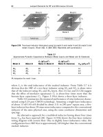
Now consider the ship shown in Figure 25.1(c), which is trimmed by the
stern and has the centre of ¯otation forward of amidships.
In this case
ZF KY KX À XY
or
True mean draft Draft amidships À correction
234 Ship Stability for Masters and Mates
e
Fig. 25.1(c)
The actual correction itself can again be found by using the above
formula, but in this case the correction is to be subtracted from the mean of
the drafts forward and aft. Similarly, by substitut ing forward for aft and aft
for forward in this ®gure, it can be seen that the correction is again to be
subtracted from the average of the drafts forward and aft when the ship is
trimmed by the head and the centre of ¯otation is aft of amidships.
A general rule may now be derived for the application of the correction
to the draft amidships in order to ®nd the true mean draft.
Rule
When the centre of ¯otation is in the same direction from amidships as the
maximum draft, the correction is to be added to the mean of the drafts.
When the centre of ¯otation is in the opposite direction from amidships to the
maximum draft, the correction is to be subtracted.
Example 1
A ship's minimum permissible freeboard is at a true mean draft of 8.5 m. The
ship's length is 120 m, centre of ¯otation being 3 m aft of amidships. TPC 50
tonnes. The present drafts are 7.36 m F and 9.00 m A. Find how much more
cargo can be loaded.
Draft forward 7X36 m
Draft aft 9X00 m
Trim 1X64 m by the stern
Correction
t ÂFY
L
1X64 Â3
120
Correction 0X04 m
Draft forward 7X36 m
Draft aft 9X00 m
Sum 16X36 m
Average Draft amidships 8X18 m
Correction 0X04 m
True mean draft 8X22 m
Load mean draft 8X50 m
Increase in draft 0X28 m or 28 cm
Cargo to load Increase in draft required ÂTPC
28 Â50
Ans.
Cargo to load 1400 tonnes
True mean draft 235
Effect of hog and sag on draft amidships
When a ship is neither hogged nor sagged the draft amidships is equal to
the mean of the drafts forward and aft. In Figure 25.1(d) the vessel is shown
in hard outline ¯oating without being hogged or sagged. The draft forward
is F, the draft aft is A, and the draft amidships (KX) is equal to the average
of the drafts forward and aft.
Now let the vessel be sagged as shown in Figure 25.1(d) by the broken
outline. The draft amidships is now K
1
X, which is equal to the mean of the
drafts forward and aft (KX), plus the sag (KK
1
). The amount of hog or sag
must therefore be taken into account in calculations involving the draft
amidships. The depth of the vessel amidships from the keel to the deck line
(KY or K
1
Y
1
) is constant being equal to the draft amidships plus the
freeboard.
Example
A ship is ¯oating in water of relative density 1.015. The present displacement is
12 000 tonnes, KG 7.7 m, KM 8.6 m. The present drafts are F 8.25 m, A 8.65 m,
and the present freeboard amidships is 1.06 m. The Summer draft is 8.53 m and
the Summer freeboard is 1.02 m FWA 160 mm TPC 20. Assuming that the KM
is constant, ®nd the amount of cargo (Kg 10.0 m) which can be loaded for the
ship to proceed to sea at the loaded Summer draft. Also ®nd the amount of the
hog or sag and the initial GM on departure.
Summer freeboard 1X02 m
Summer draft 8X53 m
Depth Mld 9X55 m
Present mean freeboard 1X06 m
Depth Mld 9X55 m
Present draft amidships 8X49 m
Average of drafts F and A 8X45 m
Ship is sagged by 0X04 m
Dock water allowance (DWA)
1025 À r
DW
25
 FWA
10
25
 160 64 mm
0X064 m
TPC in dock water
RD
DW
RD
SW
 TPC
SW
1X015
1X025
 20
19X8 tonnes
236 Ship Stability for Masters and Mates
Fig. 25.1(d)
Summer freeboard 1X020 m
DWA 0X064 m
Min. permissible freeboard 0X956 m
Present freeboard 1X060 m
Mean sinkage 0X104 m or 10.4 cm
Cargo to load Sinkage ÂTPC
dw
10X4 Â19X8
Cargo to load
205X92 tonnes
GG
1
w  d
W w
205X92 Â10 À 7X7
12 000 205X92
473X62
12 205X92
; Rise of G 0X039 m
Present GM (8.6 À7.7) 0X900 m
GM on departure 0X861 m
and ship has a sag of 0.04 m.
True mean draft 237
Exercise 25
1 The minimum permissible freeboard for a ship is at a true mean draft of
7.3 m. The present draft is 6.2 m F and 8.2 m A. TPC 10. The centre of
¯otation is 3 m aft of amidships. Length of the ship 90 m. Find how much
more cargo may be loaded.
2 A ship has a load salt water displacement of 12 000 tonnes, load draft in salt
water 8.5 m, length 120 m, TPC 15 tonnes, and centre of ¯otation 2 m aft of
amidships. The ship is at present ¯oating in dock water of density 1015 kg
per cu. m at drafts of 7.2 m F and 9.2 m A. Find the cargo which must yet be
loaded to bring the ship to the maximum permissible draft.
3 Find the weight of the cargo the ship in Question 2 could have loade d had
the centre of ¯otation been 3 m forward of amidships instead of 2 m aft.
4 A ship is ¯oating in dock water of relative density 1.020. The present
displacement is 10 000 tonnes, KG 6.02 m, KM 6.92 m. Present drafts are F
12.65 m, A 13.25 m. Present freeboard 1.05 m. Summer draft 13.10 m and
Summer freeboard is 1.01 m. FWA 150 mm. TPC 21. Assuming that the
KM is constant ®nd the amount of cargo (KG 10.0 m) which can be loaded
for the ship to sail at the load Summer draft. Find also the amou nt of the
hog or sag and the initial metacentric height on departure.
Chapter 26
The inclining
experiment
It has been shown in previous chapters that, before the stability of a ship in
any particular condition of loading can be determ ined, the initial conditions
must be known. This means knowing the ship's lightweight, the VCG or
KG at this lightweight, plus the LCG for this lightweight measured from
amidships. For example, when dealing with the height of the centre of
gravity above the keel, the initial position of the centre of gravity must be
known before the ®nal KG can be found. It is in order to ®nd the KG for the
light condition that the Inclining Experiment is performed.
The experiment is carried out by the builders when the ship is as near to
completion as possible; that is, as near to the light condition as possible.
The ship is forcibly inclined by shifting weights a ®xed distance across the
deck. The weights used are usually concrete blocks, and the inclination is
measured by the movement of plumb lines across specially constructed
battens which lie perfectly horizontal when the ship is upright. Usually two
or three plumb lines are used and each is attached at the centre line of the
ship at a height of about 10 m above the batten. If two lines are used then
one is placed forward and the other aft. If a third line is used it is usually
placed amidships. For simplicity, in the following explanation only one
weight and one plumb line is considered.
The following conditions are necessary to ensure that the KG obtained is
as accurate as possible:
1 There should be little or no wind, as this may in¯uence the inclination of
the ship. If there is any wind the ship should be head on or stern on to it.
2 The ship should be ¯oating freely. This means that nothing outside the
ship should prevent her from listing freely. There should be no barges or
lighters alongside; mooring ropes should be slacked right down, and
there should be plenty of water under the ship to ensure that at no time
during the experiment will she touch the bottom.
3 Any loose weights within the ship should be removed or secured in
place.
4 There must be no free surfaces within the ship. Bilges should be dry.
Boilers and tanks should be completely full or empty.
5 Any persons not directly concerned with the experiment should be sent
ashore.
6 The ship must be upright at the commencement of the experiment.
7 A note of `weights on' and `weights off' to complete the ship each with a
VCG and LCG
e
.
When all is ready and the ship is upright, a weight is shifted across the
deck transversely, causing the ship to list. A little time is allowed for the
ship to settle and then the de¯ection of the plumb line along the batten is
noted. If the weight is now returned to its original position the ship will
return to the upright. She may now be listed in the opposite direction. From
the de¯ections the GM is obtained as follows.
In Figure 26.1 let a mass of `w' tonnes be shifted across the deck through
a distance `d' metres. This will cause the centre of gravity of the ship to
move from G to G
1
parallel to the shift of the centre of gravity of the
weight. The ship will then list to bring G
1
vertically under M, i.e. to y
degrees list. The plumb line will thus be de¯ected along the batten from B
to C. Since AC is the new vertical, angle BAC must also be y degrees.
In triangle ABC,
cot y
AB
BC
In triangle GG
1
M,
tan y
GG
1
GM
;
GM
GG
1
AB
BC
Or
GM GG
1
Â
AB
BC
The inclining experiment 239
Fig. 26.1
But
GG
1
w  d
W
; GM
w  d
W
Â
AB
BC
Hence
GM
w  d
W tan y
In this formula AB, the length of the plumb line and BC, the de¯ection
along the batten can be measured. `w' the mass shifted, `d' the distance
through which it was shifted, and `W' the ship's displacement, will all be
known. The GM can therefore be calculated using the formula.
The naval architects will already have calculated the KM for this draft
and hence the present KG is found. By taking moments about the keel,
allowance can now be made for weights which must be loaded or
discharged to bring the ship to the light condition. In this way the light
KG is found.
Example 1
When a mass of 25 tonnes is shifted 15 m transversely across the deck of a ship
of 8000 tonnes displacement, it causes a de¯ection of 20 cm in a plumb line 4 m
long. If the KM 7 m, calculate the KG.
GM
GG
1
AB
BC
1
tan y
; tan y GM GG
1
GM
w  d
W
Â
1
tan y
25 Â 15
8000
Â
4
0X2
240 Ship Stability for Masters and Mates
ä
ä
0.94 m
6.06 m
M
7m
G
K
{
ä
ä
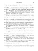
Fig. 26.2
GM 0X94 m
KM 7X00 m
Ans.
KG 6X06 m as shown in sketch on page 240.
Example 2
When a mass of 10 tonnes is shifted 12 m, transversely across the deck of a ship
with a GM of 0.6 m it causes 0.25 m de¯ection in a 10 m plumb line. Calculate
the ship's displacement.
GM
w  d
W
Â
1
tan y
W
w  d
GM
Â
1
tan y
10 Â 12 Â 10
0X6 Â 0X25
W 8000X
Ans.
Displacement 8000 tonnes
Summary
Every new ship should have an Inclining Experiment. However, some
shipowners do not request one if their ship is a sister-ship to one or more in
the company's ¯eet.
If a ship has undergone major repair or re®t, she should then have an
Inclining Exper iment to obtain her modi®ed Lightweight and centre of
gravity (VCG and LCG).
The inclining experiment 241
Fig. 26.3
242 Ship Stability for Masters and Mates
Exercise 26
1 A ship of 8000 tonnes displacement has KM 7.3 m and KG 6.1 m. A
mass of 25 tonnes is moved transversely across the deck through a distance
of 15 m. Find the de¯ection of a plumb line which is 4 m long.
2 As a result of performing the inclining experiment it was found that a ship
had an initial metacentric height of 1 m. A mass of 10 tonnes, when shifted
12 m transversely, had listed the ship 3
1
2
degrees and produced a de¯ection
of 0.25 m in the plumb line. Find the ship's displacement and the length of
the plumb line.
3 A ship has KM 6.1 m and displacement of 3150 tonnes. When a mass of
15 tonnes, already on board, is moved horizontally across the deck through
a distance of 10 m it causes 0.25 m de¯ection in an 8 m long plumb line.
Calculate the ship's KG.
4 A ship has an initial GM 0.5 m. When a mass of 25 tonnes is shifted
transversely a distance of 10 m across the deck, it causes a de¯ection of
0.4 m in a 4 m plumb line. Find the ship's displac ement.
5 A ship of 2304 tonnes displacement has an initial metacentric height of
1.2 m. Find the de¯ection in a plum b line which is suspended from a point
7.2 m above a batten when a mass of 15 tonnes, already on board, is shifted
10 m transversely across the deck.
6 During the course of an inclining experiment in a ship of 4000 tonnes
displacement, it was found that, when a mass of 12 tonnes was moved
transversely across the deck, it caused a de¯ection of 75 mm in a plumb line
which was suspended from a point 7.5 m above the batten. KM 10.2 m.
KG 7 m. Find the distance through which the mass was moved.
7 A box-shaped vessel 60 m Â10 m Â3 m is ¯oating upright in fresh water
on an even keel at 2 m draft. When a mass of 15 tonnes is moved 6 m
transversely across the deck a 6 m plumb line is de¯ected 20 cm. Find the
ship's KG.
8 The transverse section of a barge is in the form of a triangle, apex
downwards. The ship's length is 65 m, breadth at the waterline 8 m, and
the vessel is ¯oating upright in salt water on an even keel at 4 m draft.
When a mass of 13 tonnes is shifted 6 m transversely it causes 20 cm
de¯ection in a 3 m plumb line. Find the vessel's KG,
9 A ship of 8000 tonnes displacement is inclined by moving 4 tonnes
transversely through a distance of 19 m. The average de¯ections of two
pendulums, each 6 m long, was 12 cm `Weights on' to complete this ship
were 75 t centred at Kg of 7.65 m `Weights off' amounted to 25 t centred at
Kg of 8.16 m.
(a) Calculate the GM and angle of heel relating to this information, for the
ship as inclined.
(b) From Hydrostatic Curves for this ship as inclined, the KM was 9 m.
Calculate the ship's ®nal Lightweight and VCG at this weight.
Chapter 27
Effect of trim on tank
soundings
A tan k sounding pipe is usually situated at the after end of the tank and will
therefore only indicate the depth of the liquid at that end of the tank. If a
ship is trimmed by the stern, the sounding obtained will indicate a greater
depth of liquid than is actually contained in the tank. For this reason it is
desirable to ®nd the head of liquid required in the sounding pipe which will
indicate that the tank is full.
In Figure 27.1, `t' represents the trim of the ship, `L' the length of the ship,
`l' the length of a double bottom tank, and `x' the head of liquid when the
tank is full.
In triangles ABC and DEF, using the property of similar triangles:
x
l
t
L
or
Head when full
Length of tank
Trim
Length of ship
Fig. 27.1
Example 1
A ship 100 m long is trimmed 1.5 m by the stern. A double bottom tank
12 m Â10 m Â1.5 m has the sounding pipe at the after end. Find the sounding
which will indicate that the tank is full.
Head
l
Trim
L
; Head when full
1X5 Â 12
100
XorAB 0X18 m
Depth of tank 1X50 m
Ans.
Sounding when full 1X68 m
Example 2
A ship 100 m long is trimmed 2 m by the stern. A double bottom tank
15 m Â20 m Â1.5 m, which has the sounding pipe situated at the after end, is
being ®lled with fuel oil of relative density 0.8. The present tan k sounding is
1.6 m. Find the sounding when the tank is full, and also how much more oil is
required to ®ll the tank.
In Figure 27.2 the right-angled triangles ABC, CDE, and BEF are similar.
BG 1.5 m. FG the present sounding (1.6 m).
Head
l
Trim
L
Head
2 Â 15
100
Head of oil full 0X30 m
; The sounding when full 1X80 m (AG)
Also:
CD Head of oil full N present tank sounding
1X80 m N 1.60 m
CD 0X20 m
244 Ship stability
Fig. 27.2
In triangles CED and ABC:
CE
CD
BC
AB
CE
CD Â BC
AB
0X20
0X30
 15
CE 10 metres
Volume of oil yet required Area triangle CED ÂBreadth of tank
1
2
 CE ÂCD Â20
1
2
 10 Â0X20 Â20
20 cu. m
Mass of oil required Volume Âdensity
20 Â0X8
16 tonnes
Ans.
Sounding when full 1.8 m. Oil yet required 16 tonnes
Effect of trim on tank soundings 245
Exercise 27
1 A ship 120 m long is trimmed 1.5 m by the stern. A double bottom tank is
15 m Â20 m Â1 m and has the sounding pipe situated at the after end of
the tank. Find the sounding which will indicate that the tank is full.
2 A ship 120 m long is trimmed 2 m by the stern. A double bottom tank
36 m Â15 m Â1 m is being ®lled with fuel oil of relative density 0.96. The
sounding pipe is at the after end of the tank and the present sounding is
1.2 m. Find how many tonnes of oil are yet required to ®ll this tank and also
®nd the sounding when the tank is full.
Chapter 28
Drydocking and
grounding
When a ship enters a drydock she must have a positive initial GM, be
upright, and trimmed slightly, usually by the stern. On entering the
drydock the ship is lined up with her centre line vertically over the
centre line of the keel blocks and the shores are placed loosely in position.
The dock gates are then closed and pumping out commences. The rate of
pumping is reduced as the ship's stern post nears the blocks. When the stern
lands on the blocks the shores are hardened up commencing from aft and
gradually working forward so that all of the shores will be hardened up in
position by the time the ship takes the blocks overall. The rate of pumping
is then increased to quickly empty the dock.
As the water level falls in the drydock there is no effect on the ship's
stability so long as the ship is completely waterborne, but after the stern
lands on the blocks the draft aft will decrease and the trim will change by
the head. This will continue until the ship takes the blocks overall
throughout her length, when the draft will then decrease uniformly forward
and aft.
The interval of time between the stern post landing on the blocks and the
ship taking the blocks overall is referred to as the critical period. During this
period part of the weight of the ship is being borne by the blocks, and this
creates an upthrust at the stern which increases as the water level falls in the
drydock. The upthrust causes a virtual loss in metacentric height and it is
essential that positive effective metacentric height be maintained through-
out the critical period, or the ship will heel over and perhaps slip off the
blocks with disastrous results.
The purpose of this chapter is to show the methods by which the
effective metacentric height may be calculated for any instant during the
drydocking process.
Figure 28.1 shows the longitudinal section of a ship during the critical
period. `P' is the upthrust at the stern and `l' is the distance of the centre of
¯otation from aft. The trimming moment is given by P Âl. But the
trimming moment is also equal to MCTC ÂChange of trim.
Therefore,
P Â l MCTC Â t
or,
P
MCTC Â t
l
where
P the upthrust at the stern in tonnes,
t the change of trim since entering the drydock in centimetres, and
l the distance of the centre of flotation from aft in metres.
Now consider Figure 28.2 which shows a transverse section of the ship
during the critical period after she has been inclined to a small angle (y
degrees) by a force external to the ship. For the sake of clarity the angle of
heel has been magni®ed. The weight of the ship (W) acts downwards
through the centre of gravity (G). The force P acts upwards through the
keel (K) and is equal to the weight being borne by the blocks. For
equilibrium the force of buoyancy must now be (W À P) and will act
upwards through the initial metacentre (M).
Drydocking and grounding 247
Fig. 28.1
Fig. 28.2
There are, thus, three parallel forces to consider when calculating the
effect of the force P on the ship's stability. Two of these forces may be
replaced by their resultant (see page 4) in order to ®nd the effective
metacentric height and the moment of statical stability.
Method (a)
In Figure 28.3 consider the two parallel forces P and (W À P). Their
resultant W will act upwards through M
1
such that:
W À PÂy P Â X
or
W À PÂMM
1
 sin y P  KM
1
 sin y
W À PÂMM
1
P Â KM
1
W Â MM
1
À P Â MM
1
P Â KM
1
W Â MM
1
P Â KM
1
P Â MM
1
P KM
1
MM
1
P Â KM
MM
1
P Â KM
W
There are now two forces to consider: W acting upwards through M
1
and W acting downwards through G. These produce a righting moment of
W ÂGM
1
Âsin y .
Note also that the original metacentric height was GM but has now been
reduced to GM
1
. Therefore MM
1
is the virtual loss of metacentric height
due to drydocking.
248 Ship Stability for Masters and Mates
Fig. 28.3
Or
Virtual loss of GM MM
1
P Â KM
W
Method (b)
Now consider the two parallel forces W and P in Figure 28.4. Their
resultant (W ÀP) acts downwards through G
1
such that:
W Â y P Â X
or
W Â GG
1
 sin y P ÂKG
1
 sin y
W Â GG
1
P ÂKG
1
P KG GG
1
P ÂKG P Â GG
1
W Â GG
1
À P Â GG
1
P ÂKG
GG
1
W À PP Â KG
GG
1
P Â KG
W À P
There are now two forces to consider: (W ÀP) acting upwards through
M, and (W ÀP) acting downwards through G
1
. These produce a righting
moment of (W ÀP) ÂG
1
M Âsin y.
The original metacentric height was GM but has now been reduced to
G
1
M. Therefore GG
1
is the virtual loss of metacentric height due to
drydocking.
Drydocking and grounding 249
Fig. 28.4
Or
Virtual loss of GM GG
1
P Â KG
W À P
Example 1
A ship of 6000 tonnes displacement enters a drydock trimmed 0.3 m by the
stern. KM 7.5 m, KG 6 m. MCTC 90 tonnes m. The centre of ¯otation is
45 m from aft. Find the effective metacentric height at the critical instant before
the ship takes the blocks overall.
Note. Assume that the trim at the critical instant is zero.
P
MCTC Â t
l
90 Â 30
45
P 60 tonnes
Method (a)
Virtual loss of GM MM
1
P Â KM
W
60 Â 7X5
6000
0X075 m
Original GM 7X5 À 6X0 1X500 m
Ans.
New GM 1X425 m
Method (b)
Virtual loss of GM
P Â KG
W À P
GG
1
60 Â 6
5940
0X061 m
Original GM 1X500 m
Ans.
New GM 1X439 m
From these results it would appear that there are two possible answers to the
same problem, but this is not the case. The ship's ability to return to the upright
is indicated by the righting moment and not by the effective metacentric height
alone.
To illustrate this point, calculate the righting moments given by each method
when the ship is heeled to a small angle (y
)
Method (a)
Righting moment W ÂGM
1
 sin y
6000 Â1X425 Â sin y
8550 Â sin y
tonnes m.
250 Ship Stability for Masters and Mates
Method (b)
Righting moment W À PÂG
1
M Â sin y
5940 Â1X439 Â sin y
8549 Âsin y tonnes metres.
Thus each of the two methods used gives a correct indication of the ship's
stability during the critical period.
Example 2
A ship of 3000 tonnes displacement is 100 m long, has KM 6m,KG 5.5 m.
The centre of ¯otation is 2 m aft of amidships. MCTC 40 tonnes m. Find the
maximum trim for the ship to enter a drydock if the metacentric height at the
critical instant before the ship takes the blocks forward and aft is to be not less
than 0.3 m.
KM 6X0m
KG 5X5m
Original GM 0X5m
Virtual GM 0X3m
Virtual loss 0X2m
Method (a)
Virtual loss of GM MM
1
P Â KM
W
or
P
Virtual loss ÂW
KM
0X2 Â 3000
6
Maximum P 100 tonnes
But
P
MCTC Â t
l
or
Maximum t
P Â l
MCTC
100 Â 48
40
Ans.
Maximum trim 120 cm by the stern
Drydocking and grounding 251
Method (b)
Virtual loss of GM GG
1
P Â KG
W À P
0X2
P Â 5X5
3000 À P
600 À 0X2P 5X5P
5X7P 600
Maximum P
600
5X7
105X26 tonnes
But
P
MCTC Â t
l
or
Maximum t
P Â l
MCTC
105X26 Â 48
40
Ans.
Maximum trim 126X3 cm by the stern
There are therefore two possible answers to this question, depending upon
the method of solution used. The reason for this is that although the effective
metacentric height at the critical instant in each case will be the same, the
righting moments at equal angles of heel will not be the same.
Example 3
A ship of 5000 tonnes displacement enters a drydock trimmed 0.45 m by the
stern. KM 7.5 m, KG 6X0 m. MCTC 120 tonnes m. The centre of
¯otation is 60 m from aft. Find the effective metacentric height at the critical
instant before the ship takes the blocks overall, assuming that the transverse
metacentre rises 0.075 m.
P
MCTC Â t
l
120 Â 45
60
P 90 tonnes
Method (a)
Virtual loss MM
1
P Â KM
W
90 Â 7X575
5000
0X136 m
252 Ship Stability for Masters and Mates
Original KM 7X500 m
Rise of M 0X075 m
New KM 7X575 m
KG 6X000 m
GM 1X575 m
Virtual loss MM
1
0X136 m
Ans.
New GM 1X439 m
Method (b)
Virtual loss GG
1
P Â KG
W À P
90 Â 6X0
4910
0X110 m
Old KG 6X000 m
Virtual loss GG
1
0X110 m
New KG 6X110 m
New KM 7X575 m
Ans.
New GM 1X465 m
The virtual loss of GM after taking the
blocks overall
When a ship takes the blocks overall, the water level will then fall uniformly
about the ship, and for each centimetre fallen by the water level P will be
increased by a number of tonnes equal to the TPC. Also, the force P at any
time during the operation will be equal to the difference between the
weight of the ship and the weight of water she is displacing at that time.
Example 4
A ship of 5000 tonnes displacement enters a drydock on an even keel.
KM 6m. KG 5.5 m, and TPC 50 tonnes. Find the virtual loss of
metacentric height after the ship has taken the blocks and the water has
fallen another 0.24 m.
P TPC Â r eduction in draft in cm
50 Â24
P 1200 tonnes
Drydocking and grounding 253
Method (a)
Virtual lossMM
1
P Â KM
W
1200 Â 6
5000
Ans.
Virtual loss 1X44 m
Method (b)
Virtual loss GG
1
P Â KG
W À P
1200 Â 5X5
3800
Ans.
Virtual loss 1X74 m
Note to Students
In the D.Tp. examinations, when suf®cient information is given in a
question, either method of solution may be used. It has been shown in
this chapter that both are equally correct. In some questions, however, there
is no choice, as the information given is suf®cient for only one of the
methods to be used. It is therefore advisable for students to learn both of
the methods.
Example 5
A ship of 8000 tonnes displacement takes the ground on a sand bank on a
falling tide at an even keel draft of 5.2 metres. KG 4.0 metres. The predicted
depth of water over the sand bank at the following low water is 3.2 metres.
Calculate the GM at this time assuming that the KM will then be 5.0 metres
and that the mean TPC is 15 tonnes.
P TPC Â Fall in water level (cm) 15 Â(520 À320)
15 Â200
P 3000 tonnes
Method (a)
Virtual loss of GM MM
1
P Â KM
W
3000 Â 5
8000
1X88 m
Actual KM 5X00 m
Virtual KM 3X12 m
KG 4X00 m
Ans.
New GM À0X88 m
254 Ship Stability for Masters and Mates
Method (b)
Virtual loss of GM GG
1
P Â KG
W À P
3000 Â 4
5000
2X40 m
KG 4X00 m
Virtual KG 6X40 m
KM 5X00 m
Ans.
New GM À1X40 m
Note that in Example 5, this vessel has developed a negative GM.
Consequently she is unstable. She would capsize if transverse external forces
such as wind or waves were to remove her from zero angle of heel. Suggest a
change of loading to reduce KG and make GM a positive value greater that
D.Tp. minimum of 0.15 m.
Drydocking and grounding 255
EXERCISE 28
1 A ship being drydocked has a displacement of 1500 tonnes. TPC 5
tonnes, KM 3.5 m, GM 0.5 m, and has taken the blocks fore and aft at
3 m draft. Find the GM when the water level has fallen another 0.6 m.
2 A ship of 4200 tonnes displacement has GM 0.75 m and present drafts
2.7 m F and 3.7 m A. She is to enter a drydock. MCTC 120 tonnes m.
The after keel block is 60 m aft of the centre of ¯otation. At 3.2 m mean
draft KM 8 m. Find the GM on taking the blocks forward and aft.
3 A box-shaped vessel 150 m long, 10 m beam, and 5 m deep, has a mean
draft in salt water of 3 m and is trimmed 1 m by the stern, KG 3.5 m.
State whether it is safe to drydock this vessel in this condition or not, and
give reasons for your answer.
4 A ship of 6000 tonnes displacement is 120 m long and is trimmed 1 m by
the stern. KG 5.3 m, GM 0,7 m. MCTC 90 tonnes m. Is it safe to
drydock the ship in this condition? (Assume that the centre of ¯otation is
amidships.)
5 A ship of 4000 tonnes displacement, 126 m long, has KM 6.7 m.
KG 6.1 m. The centre of ¯otation is 3 m aft of amidships.
MCTC 120 tonnes m. Find the maximum trim at which the ship may
enter a drydock if the minimum GM at the critical instant is to be 0.3 m.
Chapter 29
Second moments of
areas
The second moment of an element of an area about an axis is equal to the
product of the area and the square of its distance from the axis. Let dA in
Figure 29.1 represent an element of an area and let y be its distance from
the axis AB.
The second moment of the element about AB is equal to dA Ây
2
.
To ®nd the second moment of a rectangle about an axis parallel to one of
its sides and passing through the centroid.
In Figure 29.2, l represents the length of the rectangle and b represents
the breadth. Let G be the centroid and let AB, an axis parallel to one of the
sides, pass through the centroid.
Consider the elementary strip which is shown shaded in the ®gure. The
second moment (i) of the strip about the axis AB is given by the
equation:
i lEdx  x
2
Let I
AB
be the second moment of the whole rectangle about the axis AB
then:
Fig. 29.1
I
AB
ba2
Àba2
lx
2
dx
I
AB
l
ba2
Àba2
x
2
dx
l
x
3
3
!
ba2
Àba2
I
AB
lb
3
12
To ®nd the second moment of a rectangle about one of its sides.
Consider the second moment (i) of the elementary strip shown in Figure
29.3 about the axis AB.
i lEdx  x
2
Let I
AB
be the second moment of the rectangle about the axis AB, then:
I
AB
b
O
lx
2
dx
l
x
3
3
!
b
O
Second moments of areas 257
Fig. 29.2
or
I
AB
lb
3
3
The Theorem of Parallel Axes
The second moment of an area about an axis through the centroid is equal
to the second moment about any other axis parallel to the ®rst reduced by
the product of the area and the square of the perpendicular distance
between the two axes. Thus, in Figure 29.4, if G represents the centroid
of the area (A) and the axis OZ is parallel to AB, then:
I
OZ
I
AB
À Ay
2
parallel axis theorem equation
To ®nd the second moment of a ship's waterplane area about the centre
line.
In Figure 29.5:
Area of elementary strip yEdx
Area of waterplane
L
O
yEdx
It has been shown in chapter 10 that the area under the curve can be
found by Simpson's Rules, using the values of y, the half-breadths, as
ordinates.
258 Ship Stability for Masters and Mates
Fig. 29.3
![ship stability for masters and mates [electronic resource]](https://media.store123doc.com/images/document/14/y/bj/medium_bjc1401370968.jpg)