Thermochemical Processes Episode 10 pps
Bạn đang xem bản rút gọn của tài liệu. Xem và tải ngay bản đầy đủ của tài liệu tại đây (192.67 KB, 30 trang )
262 Thermochemical Processes: Principles and Models
and
J
A
r
D
t
a
t
e
e
2
r
2
d
A
dx
Hence the rate of formation of the molecules M
a
A
b
cm
2
s
1
dn
dt
D
J
A
r
b
J
M
m
C
a
D
1
e
2
r
2
b
2
A
0
A
i
t
e
t
c
C t
a
bd
A
1
x
where x is the instantaneous thickness of the product, and A
0
and A
i
are the chemical potentials of A at the outer and inner faces of the reaction
product.
For the oxidation of NimCD2,
dn
dt
D
k
t
x
D
RT
8e
2
p
O
2
oxide/gas
p
O
2metal/oxide
t
e
t
Ni
2
C
C t
O
2
dlnp
O
2
1
x
Here, t
e
¾
D
1andt
O
2
is negligible, and thus the rate of oxidation is determined
by the partial conductivity due to the Ni
2C
ions.
If the oxidizing gas is pure oxygen, and t
Ni
2C
remains approximately constant
over the oxide thickness
k
x
D
8e
2
t
Ni
2
C
G
°
x
where G
°
is the Gibbs free energy change of the reaction
2Ni CO
2
! 2NiO
Furthermore, using the Nernst–Einstein equation to substitute in the general
equation above yields
k
t
x
D
c
0
2b
p
O
2
oxide/gas
p
O
2
metal/oxide
m
r
D
M
C D
0
dlnp
O
2
moles/cm
2
s
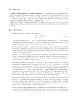
The carburizing and oxidation of transition metals
These two processes provide examples of the moving boundary problem
in diffusing systems in which a solid solution precedes the formation of a
compound. The thickness of the separate phase of the product, carbide or
Gas–solid reactions 263
0
C
s
Carbide
Gas (CH
4
)
Metal
C
II, I
C
I, II
ξ
x
direction
Figure 8.1 Schematic of the carburization of a metal
oxide, increases with time thus moving the boundary of the solid solution
phase away from the gas–solid interface.
In the kinetics of formation of carbides by reaction of the metal with CH
4
,
the diffusion equation is solved for the general case where carbon is dissolved
into the metal forming a solid solution, until the concentration at the surface
reaches saturation, when a solid carbide phase begins to develop on the free
surface. If the carbide has a thickness at a given instant and the diffusion
coefficient of carbon is D
I
in the metal and D
II
in the carbide, Fick’s 2nd law
may be written in the form (Figure 8.1)
Metal
∂c
∂t
D D
I
∂
2
c
∂x
2
x >
Carbide
∂c
∂t
D D
II
∂
2
c
∂x
2
0 Ä x Ä
for each phase.
When the metal/carbide boundary moves away from the free surface of the
sample by an increment d,theflux balance at this interface reads
C
II,I
C
I,II
d DD
II
∂c
∂x
υ
C D
I
∂c
∂x
Cυ
264 Thermochemical Processes: Principles and Models
where C
II,I
is the concentration of carbon in the carbide at the carbide/metal
interface, and C
I,II
is that in the metal at the same interface. Introducing the
relationships and definitions which were used earlier
D
D
II
D
I
;
D
2
D
II
t
1/2
and replacing
C
I,II
1 erf
1/2
by B
I
and
C
s
C
II
erf
by B
II
where C
s
is the carbon concentration in the carbide at the gas/carbide interface,
the solutions of Fick’s equations may be represented as follows:
The concentration of carbon in the carbide phase is
C
x
D C
s
B
II
erf
x
2D
II
t
1/2
0 Ä x Ä
and in the metal phase
C
x
D B
I
1 erf
x
2D
I
t
1/2
x>
and substituting into the flux balance equation at the interface
C
x
D
C
s
C
II,I
1/2
erf
exp
2
C
I,II
exp
2
1/2
[1 erf
1/2
]
and
C
II,I
C
I,II
D
B
II
exp
2
1/2
B
I
exp
2
1/2
where C
II,I
C
I,II
is the difference in the content of carbon between the
carbide and metal phases at equilibrium.
The equation for the rate of oxidation of the transition metals at high temper-
atures, which form a solid solution of oxygen before the oxide appears at the
surface has the same form as that derived for the carburizing of the metal, and
Gas–solid reactions 265
the weight change/unit area, m/A, can be expressed as a function of time by
the formula
m
A
D [Koxide formation C K
0
oxygen dissolution]
p
t D K
00
p
t
where
K D 2C
I,II
C
II,I
D
1/2
oxide
and using the definition of given above
K
0
D
2C
I,II
1/2
1 erf
1/2
D
1/2
metal
exp
2
where C
II,I
C
I,II
reflects difference between the the oxygen content of the
oxide at the oxide–metal interface, and the saturation solubility of oxygen in
the metal and is the ratio of the oxygen diffusion coefficients D
oxide
/D
metal
.
There can be little doubt that the carburization process occurs by the inward
migration of interstitial carbon atoms, and the major sources of evidence
support the view that the oxidation process in the IVA metals, Ti, Zr, and
Hf, and in the VA metals Nb and Ta, involves a predominant inward migra-
tion of oxygen ions with some participation of the metallic ions in the high
temperature regime (>1000
°
C). The mechanism of oxidation is considerably
affected by the dissolution of oxygen in the metal, leading to a low-temperature
cubic or logarithmic regime, an intermediate region of parabolic oxidation, and
then a linear regime in which the vaporization of the oxide can play a signif-
icant part. The temperature ranges in which each of these regimes operates
varies from metal to metal and to summarize, the parabolic region extends
from about 400–1100
°
C in the Group IVA elements, but the situation is much
more complicated in the Group VA elements because of the complexity of the
oxide layers which are found in the oxidation product of Nb and Ta. In these
latter elements, the parabolic regime is very limited, and mixtures of linear
and parabolic regimes are found as a function of the time of oxidation.
It is clear that the dissolution of oxygen in these metals occurs by the inward
migration of oxygen, and conforms to the parabolic law. In the oxidation of
the Group IVA metals the only oxide to be formed is the dioxide, even though
the Ti–O system shows the existence at equilibrium of several oxides. This
simplicity in the oxide structure probably accounts for the wide temperature
range of parabolic oxidation, although the non-stoichiometry of monoclinic
ZrO
2
has been invoked to account for the low-temperature behaviour of the
oxidation reaction. The mechanisms at low temperature are complicated by a
number of factors, including the stresses in the oxide layer which, unlike the
behaviour at high temperatures, cannot be relieved during oxidation. Several
explanations are given invoking the relative transport numbers of electrons
and ions, the formation of pores at the oxide/metal interface, and unrelieved
266 Thermochemical Processes: Principles and Models
stresses in the metal which change during the oxidation period as the oxygen
solution becomes more concentrated. Whatever the mechanism(s), it is signifi-
cant that the oxide is protective for a useful period of time, allowing zirconium
cladding to be used for the UO
2
fuel rods in a nuclear reactor, but this lifetime
is terminated in breakaway corrosion.
At high temperatures the change in mechanism to a linear oxidation rate,
after a short period of parabolic oxidation, indicates that the stresses in the
oxide layer which arise from the rapid rate of formation, cause rupture in the
oxide, allowing the ingress of oxygen. The cracks which are formed in the
oxide will probably vary in morphology and distribution as a function of time
of oxidation, due to the sintering process and plastic flow which will tend to
close up the cracks. The oxidation of the Group VA elements, Nb and Ta is
complicated by the existence of several oxides which are formed in sequence.
For example, the sequence in niobium oxidation is
Nb–[O]solid solution–NbO–NbO
2
–Nb
2
O
5
The pentoxide layer always appears to be porous to oxygen gas and therefore
provides no oxidation protection. The lower oxides grow more slowly, and
can adapt to the metal/oxide interfacial strains, and provide protection. The
low temperature oxidation conforms to a linear rate law after a short interval
of parabolic behaviour, corresponding to the formation of a solid solution and
a thin layer of oxide which is probably an NbO–NbO
2
(sometimes referred to
as NbO
x
) layer in platelet form, which decreases in thickness as the tempera-
ture increases. This mechanism is succeeded by a parabolic behaviour over a
longer period of time which eventually gives way to a linear growth rate as
the temperature increases above about 600
°
C. It is probable that the parabolic
behaviour in this regime is rate-determined by the formation of more substan-
tial NbO–NbO
2
layers before the pentoxide is formed.
The oxidation kinetics of the metals molybdenum and tungsten in Group
VI reflect the increasing contribution of the volatility of the oxides MoO
3
and
WO
3
as the temperature increases. At temperatures below 1000
°
C, a protec-
tive oxide, is first formed, as in the case of niobium, followed by a linear rate
when a porous layer of the trioxide is formed. There appears to be no signif-
icant solubility of oxygen in these metals, so the initial parabolic behaviour
is ascribed to the formation of the dioxide. At higher temperatures the porous
layer of oxide is restricted in thickness by increasing vaporization, and this
process further restricts the access of oxygen to the surface until a steady state
is reached, depending on the state of motion of the oxidizing atmosphere.
The oxidation of metallic carbides and silicides
The expected oxidation mechanisms of carbides and silicides can be analysed
from a thermodynamic viewpoint by a comparison of the relative stabilities
Gas–solid reactions 267
of the oxides of the metals, carbon and silicon. Thus the element having
the greater oxygen affinity would be expected to be preferentially oxidized.
However, there is a complication arising from the stabilities of the various
carbides and their solid solutions, and the stabilities of the numerous silicides
which are formed, especially by the transition metals.
The general principle that the respective sequence of oxidation of metal and
non-metal will be according to the affinity of the elements to oxygen, must
be analysed with due consideration of the thermodynamic activities and the
diffusion properties of each element. Thus in the titanium–carbon system the
affinity of titanium for oxygen is higher for the formation of rutile than is
carbon for the formation of CO(g) in the lower temperature range, and the
activity of carbon may be low if the composition of the original carbide, TiC
x
is at the upper end of the metal-rich composition. However, as the metal is
preferentially oxidized, the unburnt carbon will increase in thermodynamic
activity, and the excess of carbon will move the average composition toward
the carbon-rich end of the composition range of TiC
x
until the two-phase
region containing a mixture of the carbide and carbon is reached. The carbon
activity will increase as this occurs, and the titanium activity will fall, until
the carbon is preferentially oxidized.
The thermodynamic data for the Ti–O–C system are as follows:
Ti C O
2
! TiO
2
; G
°
D938 860 C 176.4T Jmol
1
2C CO
2
! 2CO; G
°
D224 870 174.6T Jmol
1
Ti C C D TiC; G
°
D182 750 C 5.83T Jmol
1
(The first equation ignores the existence of the intermediate titanium oxides,
which is reasonable for this analysis of the oxidation mechanism.)
When the carbide reaches carbon saturation, the titanium activity is at its
lowest value, Ti D175.754 kJ at 1200 K and 172.839 kJ at 1700 K, this
chemical potential being nearly constant over the temperature range because of
the small entropy of formation of TiC from the elements. The oxygen potential
required to form TiO
2
is less than that to form CO at one atmosphere pressure
in air at 1200 K but much higher than that to form one atmos pressure of CO
at 1700 K. There is therefore a change-over in mechanism between these two
temperatures. TiO
2
is formed at the lower temperature, and carbon particles
are left in the carbide, and at the higher temperature CO is formed, and the
composition of the carbide moves towards the liberation of carbon-saturated
titanium, thus increasing the tendency for preferential titanium oxidation.
If we combine the Gibbs energy of formation equations above to derive the
equation
Ti C 2CO ! 2C C TiO
2
; G
°
D708 490 C 347.7T Jmol
1
268 Thermochemical Processes: Principles and Models
the temperature at which this reaction has zero Gibbs energy change with the
titanium potential of the C–TiC equilibrium is about 1500 K. The changeover
in mechanism will therefore occur at about this temperature. Below 1500 K the
mechanism is the parabolic oxidation of Ti to TiO
2
, but above this temperature
the oxidation proceeds according to a linear law, with both elements being
oxidized. The CO which is formed during this reaction is oxidized to CO
2
by
the air in the atmosphere when the gas reaction takes place away from the
sample, and the gas temperature is reduced to room temperature for analysis.
The oxidation rate is decreased by a factor of four in a composite of TiC
and Cr. This is because the formation of Cr
2
O
3
covers the composite with an
oxide which oxidizes slowly because of the low transport number of electrons
through the oxide.
The oxidation of the silicides represents a competition between the forma-
tion of silica, which is very slow and controlled by oxygen permeation of the
oxide, and the oxidation of the accompanying element. The difference between
the carbides and the silicides is that there are many more silicides formed in a
binary system which vary the activities of each element, than in the carbides.
Thus in the Mo–Si system, the compounds MoSi
2
,Mo
5
Si
3
,Mo
3
Si are formed,
and in the TiSi system five silicides are formed, TiSi
2
, TiSi, Ti
5
Si
4
,Ti
5
Si
3
and
Ti
3
Si, all of which have a small range of non-stoichiometry. The preferential
oxidation of each element in either the Mo–Si or Ti–Si systems would there-
fore lead to a significant and discontinuous change in the composition near
the surface. The thermodynamic activities would show a rapid change at the
composition of any of the compounds, but remain constant in any two-phase
mixture of the compounds.
Clearly the best protection from oxidation by a silicide as a coating on a
reactive substrate would be the disilicide, which has the highest silicon content,
and could be expected to provide a relatively protective silica coating.
The oxidation of silicon carbide and nitride
The carbide has an important use as a high-temperature heating element in
oxidizing atmospheres. The kinetics of oxidation is slow enough for heating
elements made of this material to provide a substantial lifetime in service even
at temperatures as high as 1600
°
C in air. Both elements react with oxygen
during the oxidation of silicon carbide, one to produce a protective layer,
SiO
2
, and the other to produce a gaseous phase, CO(g) which escapes through
the oxide layer. The formation of the silica layer follows much the same
reaction path as in the oxidation of pure silicon, the structure of the layer
being amorphous or vitreous, depending on the temperature, and the oxidation
proceeds mainly by permeation of the oxide by oxygen molecules. The escape
of CO from the carbide/oxide interface produces a lowering of the oxygen
potential at the oxide/gas interface, which reduces the rate of oxidation, to a
Gas–solid reactions 269
level depending on the state of motion of the oxidizing gas, and can reduce
the oxide at high temperatures with the formation of SiO(g), which leads to a
reduction in the protective nature of the oxide. Because of these effects on the
oxidation kinetics, the rate of overall oxidation has been found to depend on
the flowrate, through the exchange of CO and O
2
across the boundary layer,
in the gas phase.
The nitride is an important high temperature insulator and potential compo-
nent of automobile and turbine engines and its use in oxidizing atmospheres
must be understood for several other applications. It might be anticipated that
the oxidation mechanism would be similar to that of the carbide, with the
counter-diffusion of nitrogen and oxygen replacing that of CO and O
2
.This
is so at temperatures around 1400
°
C, where the oxidation rates are similar for
the element, the carbide and the silicide, but below this temperature regime,
the oxidation proceeds more slowly, due to the operation of a different mech-
anism. At temperatures around 1200
°
C or less, the elimination of nitrogen as
N
2
molecules is replaced by a substitution of nitrogen for oxygen on the silica
lattice, the N/O ratio decreasing from the nitride/oxide interface to practically
zero at the oxide/gas interface. The oxidation rates at 1200
°
Cofthecarbide
and nitride are about 0.1 and 10
2
of that of pure silicon, and at 1000
°
C, the
oxidation rate of the nitride is less than 10
2
that of the carbide.
The technical problem in the high temperature application of Si
3
N
4
is that
unlike the pure material, which can be prepared in small quantities by CVD
for example, the commercial material is made by sintering the nitride with
additives, such as MgO. The presence of the additive increases the rate of
oxidation, when compared with the pure material, by an order of magni-
tude, probably due to the formation of liquid magnesia–silica solutions, which
provide short-circuits for oxygen diffusion. These solutions are also known to
reduce the mechanical strength at these temperatures.
Bibliography
P. Kofstad. High Temperature Oxidation of Metals. J. Wiley & Sons. New York (1966) TA 462.
K57.
N. Birks and G.H. Meier. Introduction to High Temperature Oxidation of Metals. Edward Arnold,
London (1983) QD 501.
C. Wagner. Z. Elektrochem., 63, 772 (1959).
F. Maak. Z. Metallk., 52, 545 (1961).
R.A. Rapp. Acta Met., 9, 730 (1961).
C. Wagner. Z. Phys. Chem., 21, 25 (1933).
Chapter 9
Laboratory studies of some important
industrial reactions
The reduction of haematite by hydrogen
Two alternative mechanisms were proposed for the reduction of haematite,
Fe
2
O
3
, by hydrogen (McKewan, 1958; 1960). The first proposes that the
reduction rate is determined by the rate of adsorption of hydrogen on the
surface, followed by desorption of the gaseous product H
2
O. The fact that
the product of the reaction is a porous solid made of iron metal with a core
of unreduced oxides suggests that an alternative rate-determining step might
be the counter-diffusion of hydrogen and the product water molecules in the
pores which are created in the solid reactant. The weight loss of a spherical
sample of iron oxide according to these two mechanisms is given by alternative
equations. Using W
0
as the original weight of a sphere of initial radius r
0
, W
as the weight after a period of reduction t when the radius is r,andW
f
as
the weight of the completely reduced sphere, the rate equations are:
For the interface control,
dW
dt
D kA D 4kr
2
;and
dW
dt
D
dW
dr
dr
dt
D 4r
2
dr
dt
where is the difference in density between the unreduced (oxide) and
reduced (iron) material at time t.
On integration and evaluation of the integration constant this yields
r
0
r D kt
Since
r
r
0
D
W W
f
1/3
W
0
W
f
D W
1/3
Hence
W
1/3
D 1 kt/r
0
For diffusion control
dW
dt
D
4Dp p
0
1/r 1/r
0
D4r
2
dr
dt
Laboratory studies of some important industrial reactions 271
where p and p
0
are the partial pressures of the gaseous products at the reac-
tion interface and surface of the sphere and D is the diffusion coefficient in
the gaseous phase. This equation on integration and substitution yields the
result,
3W
2/3
2W D 1 6Dt/r
2
0
In this derivation, the diffusion coefficient which is used is really a param-
eter, since it is not certain which gas diffusion rate is controlling, that of
hydrogen into a pore, or that of water vapour out of the pore. The latter seems
to be the most probable, but the path of diffusion will be very tortuous through
each pore and therefore the length of the diffusion path is ill-defined.
Although these two expressions, for surface and diffusion control are
different from one another, the graphs of these two functions as a function
of time are not sufficiently different to be easily distinguished separately. The
decisive experiment which showed that diffusion in the gas phase is the rate
determining factor used a closed-end crucible containing iron oxide sealed at
the open end by a porous plug, made from iron powder, which was weighed
continuously during the experiment. It was found that the rate of reduction
of the oxide contained in the crucible was determined by the thickness of the
porous plug, and hence it was the gaseous diffusion through this plug rather
than the interface reaction on the iron oxide, which determined the rate of
reduction (Olsson and McKewan, 1996).
Erosion reactions of carbon by gases
Gases can react with solids to form volatile oxides with some metals which
are immediately desorbed into the gas phase, depending on the temperature.
These reactions are enhanced when atomic oxygen, which can be produced in
a low-pressure discharge, is used as the reagent. Experimental studies of the
reaction between atomic oxygen and tungsten, molybdenum and carbon, show
that the rate of erosion by atomic oxygen is an order of magnitude higher
than that of diatomic oxygen at temperatures between 1000 and 1500 K, but
these rates approach the same value when the sample temperature is raised
to 2000 K or more. The atomic species is formed by passing oxygen at a
pressure of 10
3
atmos through a microwave discharge in the presence of a
readily ionized gas such as argon. The monatomic oxygen mole fraction which
is produced in the gas by this technique is about 10
2
.
A typical example of this erosion of metals is the formation of WO
2
(g)
(Rosner and Allendorf, 1970). The Gibbs energies of formation
W CO
2
D WO
2
(g); G
°
D 72 290 39T Jmol
1
log K
2000
D 0.11
272 Thermochemical Processes: Principles and Models
W C2O D WO
2
(g); G
°
D4 32 330 C 91.7T Jmol
1
log K
2000
D6.46
Since the entropies are of the opposite sign, it is clear that these reactions will
tend to the same Gibbs energy change at temperatures above 3000 K. If the
conversion of oxygen molecules to the monatomic species is complete in the
discharge, the partial pressure of WO
2
(g) should be about 10 times that in the
corresponding molecule pressure from these considerations. These equations
may also be used to deduce the Gibbs energy of formation of monatomic from
diatomic oxygen
O
2
(g) D 2O(g); G
°
D 504 620 130T Jmol
1
and these data can be used to calculate the monatomic/diatomic ratio at the
reduced pressures in space.
The most important industrial reaction of this kind occurs in the ironmaking
blast furnace in which iron oxide ore is reduced by carbon in the form of coke.
The mixture is heated by the combustion of part of the coke input in air to
produce temperatures as high as 2000 K. The reduction reaction is carried out
via the gas phase by the reaction
3CO(g) CFe
2
O
3
! 2Fe C3CO
2
(g)
the lower oxides of iron, Fe
3
O
4
andFeObeingformedasreactioninterme-
diates. The carbon dioxide is reduced to carbon monoxide by reaction with
coke according to
CO
2
C C D 2CO
The kinetics of this reaction, which can also be regarded as an erosion reaction,
shows the effects of adsorption of the reaction product in retarding the reaction
rate. The path of this reaction involves the adsorption of an oxygen atom
donated by a carbon dioxide molecule on the surface of the coke to leave a
carbon monoxide molecule in the gas phase.
CO
2
C C ! C–[O] C CO(g); rate constant k
1
C–[O] ! CO(g); rate constant k
2
The adsorption of carbon monoxide retards the reduction reaction with the
rate constant k
3
, followed by the desorption reaction with a rate constant k
4
in the overall rate equation
Rate D k
1
pCO
2
/1 Ck
3
/k
4
pCO Ck
1
/k
2
pCO
2
The description of the steady state reaction mechanism in terms of the fraction
of the active sites occupied by each adsorbed species, Â
1
for oxygen atoms
Laboratory studies of some important industrial reactions 273
and Â
2
for the carbon monoxide molecule, is as follows
k
1
pCO
2
1 Â
1
Â
2
D k
2
Â
1
shows that the rate of adsorption of CO
2
, leading to formation of the adsorbed
oxygen species, is equal to the rate of desorption of these to form carbon
monoxide in the gas phase. The corresponding balance for the adsorption and
desorption of the carbon monoxide species is as follows
k
3
pCO1 Â
1
Â
2
D k
4
Â
2
An alternative surface reaction which has been suggested is a reaction
between an adsorbed oxygen atom with an adsorbed carbon monoxide
molecule to form carbon dioxide which is immediately desorbed. The reaction
rate is again given by the equation above.
The combustion of coal
Coal contains, as well as carbon, water, which may be free in the pores
of the solid or bound in mineral hydrates, and a number of other minerals
such as SiO
2
,Al
2
O
3
,CaCO
3
and FeS
2
, together with hydrocarbons which are
referred to as ‘volatiles’. These comprise some 20–40 wt% of typical coals,
and they play an important part in the initiation of ignition prior to combus-
tion. The carbon and the volatiles contribute to heat generation during the
combustion, and the minerals usually collect in a solid ‘ash’, which only
absorbs heat, except for pyrites, which gives rise to SO
2
in the off-take
gases.
Coal is found in a wide range of carbon contents which consists of carbon
and the volatiles, from anthracite and the lower-grade bituminites to lignite,
and the relation between the combustion properties of each component of these
materials in this range of composition has a profound effect on the combustion
process. The anthracites contain the least amount of ash-forming material, but
are low in volatiles content compared with some more typical bituminous
coal. Since the volatiles play a dominant role in the initiation of combustion,
it is clear that the anthracites will not burn so readily as lower grade coals,
but have a higher carbon content, and hence represent a more compact source
of fuel.
The evolution of the volatile components begins in the temperature range
400–600
°
C, and ignition in air involves the oxygen–hydrocarbon chain reac-
tions to form CO, CO
2
and water vapour. As the temperature increases, the
direct oxidation of carbon begins to take place, probably not only at the surface
of the remaining solid material, but also in the pores which are formed during
the period of the ignition of the volatiles. The subsequent oxidation process
274 Thermochemical Processes: Principles and Models
involves the counter-diffusion of oxygen and CO
2
towards the solid and into
the pores, and the outward diffusion of carbon monoxide through a gaseous
boundary layer. Experimental data for the combustion of coal particles depend
on the flow rate of oxygen around the particles, which will determine the
boundary layer thickness, and hence the diffusion length between the atmo-
sphere and the surface of the particle. A further barrier to the burning rate
is also the condition of the ash which remains on the surface of a particles
during combustion.
More controlled studies, of the oxidation of pure graphite, are indicative of
the rates of oxidation of the post-volatilization carbon residue of a burning coal
particle (Gulbransen and Jansson, 1970). These results which were carried out
at low partial pressures of oxygen of around 40 torr, showed that the oxidation
rate depends on a chemical (interface) control at temperatures below 1000 K,
and at higher temperatures the reaction rate was determined by the diffusion
of oxygen through the boundary layer. The burning of coal in a fluidized bed
also shows a change in mechanism between 900 and 1000 K. If the weight loss
of a coal particle immersed in a fluidized bed of alumina spheres is measured
as a function of the coal particle diameter, the slope of the log (weight loss)
vs log (coal particle diameter) is less at the higher temperatures, indicating a
change-over from interface control to transport control across a boundary layer.
The oxidation of FeS — parabolic to linear rate law
transition
The results for the self-diffusion of iron in FeS
1Cυ
show that this coefficient is
orders of magnitude greater than that of sulphur and, at a given temperature,
does not alter by as much as a factor of ten across the whole composition
range. This is probably an example of a large intrinsic defect concentration
masking the effects of compositional change. It is thus to be expected that
the oxidation of ferrous sulphide will proceed by the migration of iron ions
and electrons out of the sulphide phase and into the oxide phase, leaving the
sulphur-rich sulphide.
Niwa et al. (1957) showed that this is in fact the case during the early
stages of oxidation at temperatures between 500 and 600
°
C, the oxide which
is formed being Fe
3
O
4
. The oxidation proceeds according to the parabolic rate
law, and the sample weight increases. However, this change in the sulphide
composition raises the sulphur pressure at the sulphide–oxide interface until
a partial pressure of SO
2
greater than one atmosphere can be generated. The
oxide skin then ruptures, and the weight gain as a function of time changes
from the parabolic relationship of a solid-state diffusion-controlled process to
the linear gas-transport controlled law.
Laboratory studies of some important industrial reactions 275
Oxidation of complex sulphide ores — competitive
oxidation of cations
Most sulphide minerals contain more than one metal, e.g. chalcopyrite has the
formula CuFeS
2
and pentlandite Fe, Ni
9
S
8
. Thornhill and Pidgeon (1957)
have shown semi-quantitatively how such compounds behave during oxidation
roasting by means of a metallographic study of the roasted powder specimens.
Although there exists no direct experimental evidence at present, it is probable
that the diffusion coefficients of both metallic species are about the same, and
both are very much larger than that of sulphur. It should then follow that
the metal which undergoes the greater reduction in chemical potential by
oxidation, i.e. forms the more stable oxide, will be preferentially removed.
Thus, FeO is considerably more stable than Cu
2
O and so iron should be
preferentially oxidized from chalcopyrite. The resulting copper sulphide after
a period of oxidation of CuFeS
2
was shown by the authors to give the X-
ray pattern of digenite Cu
9
S
5
. The acid-soluble oxide layer which had been
formed on the surface was iron oxide (Table 9.1).
Table 9.1 Roasting of 30–40 mesh CuFeS
2
at 550
°
C
Time (minutes) Sulphide analysis Phase
Wt % Cu Wt % Fe present
Zero 35.3 30.6 Chalcopyrite
20 60.6 8.3 Mauve digenite
35 68.0 zero Blue digenite
(Covellite)
The difference in stability between FeO and NiO is not as large as that
between iron and copper oxides, and so the preferential oxidation of iron is
not so marked in pentlandite. Furthermore, the nickel and iron monoxides
form a continuous series of solid solutions, and so a small amount of nickel
is always removed into the oxide phase (Table 9.2).
The kinetics of the processes of oxidation of these complex sulphides have
not been established quantitively, but the rate of advance of the oxides into
sulphide particles of irregular shapes were always linear. This suggests that
the oxide films were ruptured during growth thus permitting the gas phase
to have relatively unimpeded access to the sulphide–oxide interface in all
cases.
276 Thermochemical Processes: Principles and Models
Table 9.2 Roasting 65–80 mesh Fe, Ni
9
S
8
at 600
°
C
Sulphide analysis Wt % Ni Wt % Fe Phases
Time (Min.) present
Zero 35.1 32.3 Pentlandite
65 42.2 22.0 Pyrrhotite
type.
The kinetics of sulphation roasting
The objective in sulphation roasing is to produce water-soluble products which
can be used in the hydrometallurgical extraction of metals by aqueous elec-
trolysis. The sulphation reaction is normally carried out on oxides which are
the products of sulphide roasting, as described above. A few studies have been
made of the rates at which sulphates can be formed on oxides under controlled
temperatures and gas composition. The mechanism changes considerably from
one oxide to another, and there is a wide variability in the rates (Alcock and
Hocking, 1966). The thermodynamics of sulphates shows that the dissociation
pressures of a number of the sulphates of the common metals, iron, copper,
nickel, etc., reach one atmosphere at quite low temperatures, less than 1000
°
C.
At around 600
°
C, most of these sulphates have very low dissociation pressures.
Thus, CoSO
4
has a dissociation SO
3
pressure of 10
5
atmosatthistempera-
ture. It follows that when a study of the kinetics of sulphation of these oxides
is carried out over this temperature range, 600–1000
°
C, the SO
3
pressure
exerted at the oxide–sulphate interface will change by five orders of magni-
tude if local equilibrium prevails. At the same time, the diffusion processes
through the sulphate product layer will increase with increasing temperature
over this same interval, following a normal Arrhenius relationship between
diffusion coefficients and the temperature. Under the right circumstances, it
could, and in some instances does, happen that the overall rate of the process
would be seen to pass through a maximum somewhere in the temperature
interval 600–1000
°
C because the rate is dependent on the flux of particles
across the product, and hence on the chemical potential gradient multiplied
by the diffusion coefficient. This situation is exactly parallel to those which
bring about T–T–T transformation in metallic systems.
The sulphation of cobalt oxide, CoO, follows the parabolic law up to 700
°
C
and above 850
°
C, proceeding by outward diffusion of cobalt and oxygen ions
through a sulphate layer which is coherent up to about 700
°
C. The mechanism
Laboratory studies of some important industrial reactions 277
changes above this temperature, which is where the rate optimum should be
found, above a limiting thickness at intermediate temperatures and it becomes
coherent again above 850
°
C with parabolic kinetics. The rate of sulphate
formation passes through a maximum in the intermediate temperature zone
probably because the diffusion coefficients are low at low temperatures while
the chemical potential gradients across the sulphate are high, whereas the
converse applies at high temperatures. It is observed that the rate law is the
linear law in the intermediate, high velocity, region, and the sulphate layer
is seen to be cracked. In the upper and lower temperature regions, where the
reaction is parabolic, the sulphate layer is smooth and uncracked.
Heat transfer in gas–solid reactions
When a gas reacts with a solid, heat will be transferred from the solid to the gas
when the reaction is exothermic, and from gas to solid during an endothermic
reaction. The energy which is generated will be distributed between the gas
and solid phases according to the temperature difference between the two
phases, and their respective thermal conductivities. If the surface temperature
of the solid is T
2
at any given instant, and that of the bulk of the gas phase
is T
1
, the rate of convective heat transfer from the solid to the gas may be
represented by the equation
dQ
dt
D hT
2
T
1
per unit area
where h is the heat transfer coefficient of the gas. The fraction of the energy
generated in unit time which is transferred to the gas is given by
F D
h
Ä
s
T
2
T
1
where Ä
s
is the thermal conductivity of the solid.
The value of the heat transfer coefficient of the gas is dependent on the rate
of flow of the gas, and on whether the gas is in streamline or turbulent flow.
This factor depends on the flow rate of the gas and on physical properties
of the gas, namely the density and viscosity. In the application of models of
chemical reactors in which gas–solid reactions are carried out, it is useful to
define a dimensionless number criterion which can be used to determine the
state of flow of the gas no matter what the physical dimensions of the reactor
and its solid content. Such a criterion which is used is the Reynolds number of
the gas. For example, the characteristic length in the definition of this number
when a gas is flowing along a tube is the diameter of the tube. The value of
the Reynolds number when the gas is in streamline, or linear flow, is less than
about 2000, and above this number the gas is in turbulent flow. For the flow
278 Thermochemical Processes: Principles and Models
of a gas around a spherical particle the critical value of the Reynolds number
is about 500, the characteristic length being the diameter of the particle. When
a gas passes over a flat surface of length L, the heat transfer coefficient is a
function of the length x along the surface according to
h
x
x/Ä D 0.64ux/Á1/2C
p
Á/Ä1/3
for streamline flow, and
h
x
x/Ä D 0.023ux/Á4/5C
p
Á/Ä1/3
for turbulent flow.
There are three dimensionless numbers used in these equations, and their
definitions are:
u
x
/Á D Reynolds number, N
Re
, at the point x along the surface,
h
x
x/Ä is the Nusselt number,N
Nu
and C
p
Á/Ä is the Prandtl number,N
Pr
.
The relation given above for streamline flow can therefore be expressed as
N
Nu
D 0.64N
1/2
Re
N
1/3
Pr
In the definition of the Prandtl number, C
p
is the heat capacity of the gas at
constant pressure.
Over the length of the solid the average value of the heat transfer coefficient
hav is given by
hav D 1/L
h
x
dx
from 0 to L. In most circumstances of streamline flow of a gas, the Prandtl
number may be taken as approximately one, since this number only varies
between 0.5 and 1.0. The Reynolds number is therefore the most significant
number in determining the Nusselt number. Generally speaking, when the
surface of the solid is rough, turbulent conditions are likely to apply, even
when the Reynolds number has the value of 100.
For low values of the Reynolds number, such as 10, where streamline flow
should certainly apply, the Nusselt number has a value of about 2, and a
typical value of the average heat transfer coefficient is 10
4
. For a Reynolds
number of 104, where the gas is certainly in turbulent flow, the value of the
Nusselt number is typically 20. Hence there is only a difference of a factor of
ten in the heat transfer coefficient between these two extreme cases.
The Nusselt number for the heat transfer between a gas and a solid particle
of radius d, is given by the Ranz–Marshall equation
Laboratory studies of some important industrial reactions 279
N
Nu
D 2.0 C0.6 N
1/2
Re
N
1/3
Pr
where the corresponding Reynolds number is defined by
N
Re
D du/
This yields a value of 4 for the Nusselt number in a situation where N
Re
is
about 10, which is typical of a small laboratory study.
The Rowe–Claxton empirical equation has been found to conform to many
experimental studies of heat transfer in a packed bed, such as the reactor
typically used in the catalytic processes described earlier. It is first necessary
in this situation to define the voidage of the system, V,where
V D total volume of bed volume of solid particles
The equation then becomes
hd
s
/Ä
g
D A CBN
n
Re
N
1/3
Pr
where
A D 2/1 V
1/3
B D 2/3V
and the exponent n is defined by the equation
2 3n
3n 1
D 4.65 N
0.28
Re
d
s
is the diameter of the particles, and Ä
g
is the thermal conductivity of the
gas.
The above equations for heat transfer apply when there is no heat generation
or absorption during the reaction, and the temperature difference between the
solid and the gas phase can be simply defined throughout the reaction by
a single value. Normally this is not the case, and due to the heat of the
reaction(s) which occur there will be a change in the average temperature
with time. Furthermore, in the case where a chemical reaction, such as the
reduction of an oxide, occurs during the ascent of the gas in the reactor, the
heat transfer coefficient of the gas will vary with the composition of the gas
phase.
Industrial reactors for iron ore reduction to solid iron
The reduction of iron ores is carried out on the large industrial scale in the iron-
making blast furnace, where CO is the reducing gas and the product is liquid
280 Thermochemical Processes: Principles and Models
iron saturated in carbon. Alternatively, several designs of packed bed reactors
have been proposed, in which the reducing gas is frequently the reformed
mixture of CO, H
2
and N
2
obtained from the reaction between natural gas
and air, and the product is solid iron powder which has been sintered to form
porous pellets.
The reaction mechanism for the solid state reduction is the same as that
described above for the hydrogen reduction of haematite, namely the formation
of a porous iron product which results from the penetration of pores in the
reacting pellets by reducing gases, and the migration of the reaction products,
CO
2
and H
2
O through these pores back into the gaseous phase.
The solid iron ore is formed into pellets, which are presented to the gas in a
vertical shaft containing the pellets in the form of a packed bed. The reducing
gas enters the shaft at the bottom and rises through the packed bed reacting to
form gaseous oxidation products, CO
2
and H
2
O. The heat required to raise the
reactants to a temperature at which the reaction rate is fast enough is usually
carried by the inlet gas phase.
In order to analyse the packed bed process, it is necessary to consider
both heat transfer from the solid to the gas and reaction heat which may be
transmitted to the gas. The composition of the gas, and hence its physical
properties, are determined by the rate of reduction, which in turn depends
on each layer of the packed bed, and on the degree of reduction which has
already occurred. In the reduction of haematite, there are three stages in the
reduction, corresponding to the formation of Fe
3
O
4
and FeO before the metal
is formed. The thermal data for the reduction processes can be approximated
by the respective heats of reduction by H
2
and CO gases. Taking 1000
°
C
as a typical mean temperature, the mean value for the heats of reaction per
2 gram-atom of iron are
Fe
2
O
3
C H
2
! Fe
3
O
4
C H
2
O H
°
DC5.8 kJ per 2 gram-atom Fe
Fe
3
O
4
C H
2
! FeO CH
2
O H
°
DC26 kJ 2 gram-atom
FeO CH
2
! Fe CH
2
O H
°
DC28 kJ 2 gram-atom
For complete reduction of Fe
2
O
3
by hydrogen
H
°
D 59.8kJmol
1
Fe
2
O
3
and for CO reduction
Fe
2
O
3
C CO ! Fe
3
O
4
C CO
2
H
°
D5.2kJper 2gram-atom Fe
Fe
3
O
4
C CO ! FeO C CO
2
H
°
D 5.3kJ 2gram-atom
FeO CCO ! Fe CCO
2
H
°
D38.9kJ 2gram-atom
For complete reduction of Fe
2
O
3
by carbon monoxide
H
°
D38.8kJmol
1
Fe
2
O
3
Laboratory studies of some important industrial reactions 281
Since the reforming of CH
4
produces 1 mole of CO for each 2 moles of H
2
,
the dominant heat effect in the reduction process is the endothermic reduction
by hydrogen. However, since the reforming process is carried out with air as
the source of oxygen, the heat content of the nitrogen component is a thermal
reservoir for the overall reduction process.
The heat of formation of the reformed products is
CH
4
C 1/2O
2
D CO C2H
2
H
°
1273
D21.600 kJ mol
1
CH
4
or at complete reaction
CH
4
C 2O
2
D CO
2
C 2H
2
O H
°
1273
D80 250 kJ mol
1
CH
4
The heat contents of the Fe
2
O
3
and the gases at 1000
°
CinkJmol
1
which are
involved in the process are Fe
2
O
3
: 140, H
2
: 29, CO : 25, N
2
: 31, CO
2
: 48,
and H
2
O : 37.5
It is quite clear from these data that the reducing gas phase must be pre-heated
before being used in the reduction shaft, and that the addition of an excess of
oxygen over the amount required to form CO and H
2
only, provides a larger
source of reaction heat but less reducing power. The pre-heating of the CO/H
2
mixture to 1000
°
C adds about 84 kJ mol
1
CH
4
to the ingoing enthalpy content
of the gas. In order to avoid the possibility of soot particle formation during
the reforming process, it is preferable to add a small excess of oxygen over
the stoichiometric composition for CO formation, and thus also profit from the
small increase in the heat content of the product, which will now contain a small
partial pressure of CO
2
and H
2
O. The thermodynamic data for the degree of
reduction which can be carried out by the reducing gas, show that about 50% of
the reductant can be used to produce iron from ‘FeO’, the non-stoichiometric
oxide of iron and from Fe
3
O
4
, after which the resulting gas serves only as a
reductant for Fe
2
O
3
to Fe
3
O
4
, and as a pre-heater for the unreduced material.
Pilot plant tests which confirm these data show that the percentage utilization
of a gas mixture of 2:1 H
2
with CO containing 38% N
2
and a few per cent of
CO
2
and H
2
O, which is pre-heated to 1000
°
C, is between 35 and 40%, with a
throughput volume of 1400–1600 m
3
of reducing gas per ton Fe
2
O
3
(in pellet
form of diameter 3.1 cm). The reactor produces about 16 tons of iron sponge
per day from a packed bed of 3 m height and 130 cm diameter. Ancillary
experimental data show that the time for complete reduction of 400 g Fe
2
O
3
pellets is about 20 minutes under comparable flow rates with the same gas
mixture in a smaller laboratory system.
The industrial roasting of sulphides
The objective in the roasting of sulphides, such as copper sulphides and zinc
sulphides, is to convert these into their corresponding oxides by reaction with
282 Thermochemical Processes: Principles and Models
air. The two most successful methods for doing this are the moving bed and
the fluidized bed roasters. In both arrangements the reaction of oxidation in
air is highly exothermic, and the gaseous products contain oxides of sulphur.
The reactions are usually carried out at mean temperatures below 1500 K, and
the products are solid oxides in which the total surface area is considerably
higher than that of the reactant.
The first successful study which clarified the mechanism of roasting, was a
study of the oxidation of pyrite, FeS
2
, which is not a typical industrial process
because of the availability of oxide iron ores. The experiment does, however,
show the main features of roasting reactions in a simplified way which is well
supported by the necessary thermodynamic data. The Gibbs energy data for
the two sulphides of iron are,
Fe CS
2
(g) D FeS
2
pyrite
G
°
D297 440 C 196.7Jmol
1
and
2Fe CS
2
(g) D 2FeS (pyrrhotite)
G
°
D309 770 C 117.7T Jmol
1
It can be readily calculated that pyrite will exert a sulphur dissociation pressure
of 1 atmos only at 1512 K. However, when the sulphide reacts with air the
main gaseous product is SO
2
, and the reaction is then
3FeS
2
C 8O
2
D Fe
3
O
4
C 6SO
2
G
°
D2 362 800 C142.4T Jmol
1
which is an extremely exothermic reaction. Because of this the oxide layer
which is formed on the surface of the sulphide is cracked, thus admitting more
oxygen to the residual sulphide kernel.
The corresponding reaction for the oxidation of pyrrhotite has a somewhat
different behaviour. There is an initial reaction leading to the formation of
SO
2
, but no formation of the oxide layer. After a period of oxidation in this
mode, the reaction shown by pyrite occurs, with the formation of a cracked
oxide product. During the initial ‘quiet’ period it is found that the sulphur/iron
ratio in the sample increases and iron is removed to the surface as magnetite,
until a critical state is reached where oxidation of sulphur occurs. Pyrrhotite is
known to show a range of composition, and it is this range which is traversed
before the oxidation of sulphur occurs. Clearly, the iron is initially removed
from the interior of the solid to the gas–solid interface where it has a lower
chemical potential in combination with oxygen. This phenomenon is common
among sulphides, and when these are complex, i.e. they contain more than
Laboratory studies of some important industrial reactions 283
one metal, as in the case of chalcopyrite, CuFeS
2
, the metal which forms
the more stable oxide, in this case iron, is preferentially removed from the
sulphide by oxidation, the remaining kernel being more rich in copper than
the original ore.
The industrial methods for carrying out these reactions involve the oxidation of
separate particles, or the oxidation of thick layers of sulphide. In the flash roaster
particles are dropped down a tower to fall under gravity, in an atmosphere of
air. The particles are assumed to interact completely with the atmosphere during
free fall. In fluosolid roasting the particles are reacted in an upward flow of air,
which keeps the particles floating in the gas phase as well as being separated.
The roasted products are removed from the reactor by increasing the gas flow
rate. The flow rate of gas necessary to support the particles will clearly be a
compromise, because of the distribution of sizes of the particles.
In the fixed-bed and moving-bed roasters, the bed of particles is ignited by
the roasting reaction in air and slowly moved through the reactor either by
a moving belt, or down a series of horizontal stages by the action of rotary
rakes which slowly sweep the material across each stage, finally to fall a short
distance to the next stage.
In all of these systems, the rate of generation at the gas–solid interface is
so rapid that only a small fraction is carried away from the particle surface by
convective heat transfer. The major source of heat loss from the particles is
radiation loss to the surrounding atmosphere, and the loss per particle may be
estimated using unity for both the view factor and the emissivity as an upper
limit from this source. The practical observation is that the solids in all of
these methods of roasting reach temperatures of about 1200–1800 K.
The corrosion of metals in multicomponent gases
The reaction of metals with gas mixtures such as CO/CO
2
and SO
2
/O
2
can lead
to products in which the reaction of the oxygen potential in the gas mixture to
form the metal oxides is accompanied by the formation of carbon solutions or
carbides in the first case, and sulphide or sulphates in the second mixture. Since
the most important aspects of this subject relate to the performance of materials
in high temperature service, the reactions are referred to as hot corrosion
reactions. These reactions frequently result in the formation of a liquid as
an intermediate phase, but are included here because the solid products are
usually rate-determining in the corrosion reactions.
As an example of the mechanism of these corrosion reactions, the oxidation
of metals containing a carbide-forming element, e.g. chromium in Fe–Ni–Cr
stainless steels, by CO
2
/CO gas mixtures leads to the formation of an oxide
which would typically contain grain boundaries. When the reacting gas mixture
permeates the oxide, by grain boundary diffusion, the gas mixture will equi-
librate with the oxide scale, following the oxygen potential gradient in the
284 Thermochemical Processes: Principles and Models
oxide. As the gas approaches the metal/oxide interface, the composition of the
gas will have been substantially enriched in CO, and if the resulting CO/CO
2
mixture has a high enough carbon potential, then carbide particles will be
formed at or near the interface.
Aircraft turbines in jet engines are usually fabricated from nickel-based
alloys, and these are subject to combustion products containing compounds
of sulphur, such as SO
2
, and oxides of vanadium. Early studies of the corro-
sion of pure nickel by a 1:1 mixture of SO
2
and O
2
showed that the rate of
attack increased substantially between 922 K and 961 K. The nickel–sulphur
phase diagram shows that a eutectic is formed at 910 K, and hence a liquid
phase could play a significant role in the process. Microscopic observation
of corroded samples showed islands of a separate phase in the nickel oxide
formed by oxidation, which were concentrated near the nickel/oxide interface.
The islands were shown by electron microprobe analysis to contain between
30 and 40 atom per cent of sulphur, hence suggesting the composition Ni
3
S
2
when the composition of the corroding gas was varied between SO
2
:O
2
equal
to 12:1 to 1:9. The rate of corrosion decreased at temperatures above 922 K.
The thermodynamic activity of nickel in the nickel oxide layer varies from
unity in contact with the metal phase, to 10
8
in contact with the gaseous
atmosphere at 950 K. The sulphur partial pressure as S
2
(g) is of the order of
10
30
in the gas phase, and about 10
10
in nickel sulphide in contact with nickel.
It therefore appears that the process involves the uphill pumping of sulphur
across this potential gradient. This cannot occur by the counter-migration of
oxygen and sulphur since the mobile species in the oxide is the nickel ion, and
the diffusion coefficient and solubility of sulphur in the oxide are both very low.
It was shown earlier that the oxidation rate of nickel at this temperature is
dominated by grain boundary migration, and therefore the possibility exists
that SO
2
can diffuse through the boundaries, and penetrate the oxide. If this is
so then the diffusing species will come into contact with a decreasing oxygen
partial pressure as it penetrates the oxide, and will therefore exert a higher
sulphur dissociation pressure. When the oxygen partial pressure is 10
16
at
the metal/oxide interface, this pressure would be nearly one atmosphere, if the
original partial pressure of SO
2
were one atmosphere. This can clearly not be
the case since there would be no driving force for SO
2
diffusion from the gas
phase, across the boundary layer and through the oxide. Even if this pressure
were 10
6
atmos at the metal/oxide interface, however, the sulphur pressure
would be high enough to allow the formation of Ni
3
S
2
.
The thermodynamic data for this discussion are:
2Ni CO
2
D 2NiO; G
°
D478 500 C 177T J
3Ni CS
2
D Ni
3
S
2
; G
°
D350 400 C 180.7T
S
2
C 2O
2
D 2SO
2
; G
°
D723 100 C 144.6T
Laboratory studies of some important industrial reactions 285
Bibliography
W.M. McKewan. Trans. AIME, 212, 791 (1958), ibid. 218, 2 (1960).
R.G. Olsson and W.M. McKewan. Trans. AIME, 236, 1518 (1966).
D.E. Rosner and H.D. Allendorf. Heterogeneous Kinetics at Elevated Temperatures, G.R. Belton
and W.L. Worrell (eds), p. 231. Plenum Press, New York (1970).
E.A. Gulbransen and S.A. Jansson. ibid., p. 181.
K. Niwa, T. Wada and Y. Shiraishi. Trans. AIME, 209, 269 (1957).
P.G. Thornhill and L.M. Pidgeon. ibid., 209, 989 (1957).
C.B. Alcock and M.G. Hocking. Trans. I.M.M., 75, C27 (1966).
L. von Bogdandy and H.J. Engell. TheReductionofIronOres. Springer Verlag, Berlin (1971).
M. Radovanovic. Fluidized Bed Combustion. Hemisphere Publishing Corp, New York (1985) TJ
254.5 F585.
Appendix: Thermodynamic data for the Gibbs energy of
formation of metal oxides
Group IA Oxides
4Li CO
2
! 2Li
2
O G
°
D1196 800 C 249.3T 300–450
Liquid Li D1210 400 C 279.4T 450–700
4Na CO
2
! 2Na
2
O G
°
D830 180 C 260.3 300–350
Liquid Na D844 140 C 289.3T 400–500
4K CO
2
! 2K
2
O G
°
D729 100 C 287.3T 400–700
Liquid K only
4Rb CO
2
! 2Rb
2
O G
°
D699 840 C 278.9T 350–700
Liquid Rb only
4Cs CO
2
! 2Cs
2
O G
°
D685 720 C 288T 350–700
Liquid Cs only
Group IB
4Cu CO
2
! 2Cu
2
O G
°
D344 180 C 147.2T 300–1300
Liquid Cu D328 510 C 136.2T 1300–1700
2Cu
2
O CO
2
! 4CuO G
°
D290 690 C 196.2T 300–1200
4Ag CO
2
! 2Ag
2
O G
°
D61 780 C 132T 298–450
Group IIA
2Be CO
2
! 2BeO G
°
D1 217 200 C194.1T 298–1557
Liquid Be D1 213 400 C191.0T 1557–2000
2Mg CO
2
! 2MgO G
°
D1 206 300 C273.7T 300–900
Liquid Mg D1 201 400 C270.0T 1000–1350
286 Thermochemical Processes: Principles and Models
2Ca CO
2
! 2CaO G
°
D1 267 600 C206.2T 298–1124
Liquid Ca D1 282 900 C219.8T 1124–1760
2Sr CO
2
! 2SrO G
°
D1 181 500 C191.8T 300–1000
Liquid Sr D1 194 300 C204.1T 1050–1600
2Ba CO
2
! 2BaO G
°
D1 093 600 C178.9T 300–980
Liquid Ba D1 106 800 C191.8T 983–1600
Group IIb
2Zn CO
2
! 2ZnO G
°
D699 920 C 198.3T 300–650
Liquid Zr D711 120 C 214.1T 700–1000
2Cd CO
2
! 2CdO G
°
D515 500 C 195.5T 298–590
Liquid Cd D524 590 C 210.7T 600–900
2Hg CO
2
! 2HgO G
°
D108 900 C 214.3T 300–600
Liquid Hg only
Group IIIA
4/3B CO
2
! 2/3B
2
O
3
G
°
D848 130 C 177.0T 300–700
Liquid B
2
O
3
D827 040 C 147.9T 750–1200
4/3Al CO
2
! 2/3Al
2
O
3
G
°
D1 115 700 C208.3T 298–923
Liquid Al D1 124 800 C218.3T 923–1800
4/3Sc CO
2
! 2/3Sc
2
O
3
G
°
D1 268 900 C196.1T 300–1700
2/3Y CO
2
! 2/3Y
2
O
3
D1 264 300 C189.2T 300–1700
4/3La CO
2
! 2/3La
2
O
3
D1 191 800 C187.4T 300–1000
Liquid La D1 196 400 C190.4T 1150–1600
4/3Sm CO
2
! 2/3Sm
2
O
3
G
°
D1 211 800 C191.9T 300–1300
4/3Eu CO
2
! 2/3Eu
2
O
3
D1 198 000 C197.4T 300–1050
4/3Gd CO
2
! 2/3Gd
2
O
3
D1 212 800 C187.7T 300–1500
Group IIIB
4/3Ga CO
2
! 2/3Ga
2
O
3
G
°
D731 090 C 223.7T 300–1000
Liquid Ga only
4/3In CO
2
! 2/3In
2
O
3
G
°
D618 160 C 215.2T 450–1000
Liquid In only
4Tl CO
2
! 2Tl
2
O G
°
D334 360 C 192.1T 300–550
Liquid Tl D350 670 C 220.8T 600–850
Tl
2
O CO
2
! Tl
2
O
3
G
°
D221 020 C 196.4T 300–800