Know and Understand Centrifugal Pumps Episode 2 pdf
Bạn đang xem bản rút gọn của tài liệu. Xem và tải ngay bản đầy đủ của tài liệu tại đây (622.64 KB, 20 trang )
Know and Understand Centrifugal Pumps
and pressure is added to the liquid (again Bernoulli’s Principle). The
liquid leaves the pump
at
discharge pressure, prepared
to
overcome the
resistance in the system.
The flow from
a
centrihgal pump is mostly governed by the speed of
the driver and the height of the impeller blades. The pressure or head
that the pump can generate is mostly governed by the speed of
the
motor and the diameter of the impeller. Other factors play a lesser role
in the pump’s flow and pressure, like the number, pitch, and thickness
of the impeller blades, the internal clearances, and the presence and
condition of the wear bands.
In simple terms,
we
could say that
PD
pumps perform work
by
manipulating the available space inside the pump. Centrihgal pumps
perform work by manipulating the velocity of the fluid as
it
moves
through the pump. There is more on this in Chapter
6.
Pressure measurement
Force (F)
is equal
to
Pressure
(P)
multiplied by the
Area
(A):
F=P
xA.
F
Pressure
is equal
to
the
Force
divided by the
Area:
P
=
-
A
If we apply pressure
to
the surface of a liquid, the pressure is
transmitted uniformly in all directions across the surface and even
through the liquid
to
the walls and bottom of the vessel containing
the
liquid (Pascal’s Law). This is expressed as pounds per square inch
(lbs/in2, or psi), or kilograms per square centimeter (k/cm2).
Atmospheric pressure (ATM)
Atmospheric pressure (ATM) is the force exerted by the weight of the
atmosphere on a unit of area.
ATM
=
14.7
psia
at sea level. As
elevation rises above sea level, the atmospheric pressure is less.
__
Absolute pressure (psia)
Absolute pressure is the pressure measured from a zero pressure
reference. Absolute pressure is
14.7
psia at sea level. Compound
pressure gauges record absolute pressure.
4
Basic Pump Principles
Gauge pressure (psig)
Gauge pressure is the pressure indicated on a simple pressure gauge.
Simple pressure gauges establish an artificial zero reference at
atmospheric pressure. The formula is:
psig
=
psia
-
ATM.
~ ~~~
Vacuum
___
-
The term vacuum is used
to
express pressures less than atmospheric
pressure (sometimes represented as a negative psi on pressure gauges).
Another scale frequently used is ‘inches of mercury’. The conversion is:
14.7
psia
=
29.92”
Hg.
Another scale gaining in popularity is the
kilopascal
(Kp)
scale.
14.7
psia
=
100
Kp
Note that there are many ways to express vacuum. Simple gauges record vacuum as a
negative psig. Compound gauges record vacuum as a positive psia. The weatherman
uses inches of mercury in the daily forecast, and millibars
(1000
millibars is
atmospheric pressure) to express the low-pressure zone in the eye of a hurricane.
Boiler operators use water column inches and millimeters of mercury to express
vacuum.
Pump manufacturers express vacuum in aspirated feet of water in a vertical column
(0
psia
=
-33.9
feet
of
water). The pharmaceutical and chemical industry uses
‘Pascals’
(100,000
Pascals
=
atmospheric pressure) and the term TORR. This
conglomeration of values and conversion rates causes confusion. In order to
understand pumps, it‘s best to think of vacuum as a positive number less than
14.7
psi.
In
our experience, we’ve found that considering vacuum
in
this form aids the
understanding of net positive suction head
(NPSH),
cavitation, suction specific speed
(Nss), and the ability of pumps to suck-up (actually pumps don’t suck, but this will do
for now) fluid from below. Remember that vacuum is the absence of atmospheric
pressure, but
it
is not a negative number.
Pump head
The term ‘pump head’ represents the net work performed on the liquid
by the pump.
It
is
composed of four parts. They are: the static head
(Hs),
or
elevation; the pressure head (Hp) or the pressures
to
be
overcome; the friction head
(Hf)
and velocity head
(Hf),
which are
frictions and other resistances in the piping system. These heads are
discussed in Chapter
8.
The head formula is the following:
5
Know
and Understand Centrifugal Pumps
Where:
H
=
head
P
=
psi
d
=
density
Pressure can be converted into head with the following equation:
2.31
x
Pressure psi
sp.gr.
Head@.
=
Where:
H
=
head in feet
2.31=
conversion factor
psi
=
pressure in pounds per square inch
sp.
gr.
=
specific gravity
Head converts
to
pressure with the following formula:
Head@.
x
sp.8~
2.31
Pressure psi
=
Specific gravity
Specific gravity is the comparison of the density of
a
liquid with the
density of water. With pumps,
it
is used
to
convert head into pressure.
The specific gravity formula is:
Density Liquid
Density Water
Sp.Gz
=
The standard for water is
60°F
at sea level.
Water is designated
a
specific gravity of
1.0.
Another liquid is either
heavier (denser) or lighter than water. The volume is not important as
long as we compare equal volumes. The specific gravity affects the
pressure in relation
to
the head, and
it
affects the horsepower
consumed by the pump with respect
to
pressure and flow. We’ll study
this in depth later.
Pressure measurement
Pressure exists in our daily lives. At sea level
the
atmospheric pressure is
14.7
psia. This is the pressure exerted on us by the air we breathe. If
we
should remove all the air, then
the
pressure would be zero.
Basic Pump Principles
We’re more concerned with pressures above atmospheric pressure. For
example, a flat tire on
a
car still has
14.7
pounds of pressure inside it.
We would consider this
to
be a flat tire because the pressure outside the
tire is equal
to
the pressure inside the tire.
We
would say the tire has no
pressure because
it
would not be inflated and could not support the
weight of the car.
What is more important
to
us is
the
differential pressure inside the tire
compared
to
outside the tire (atmospheric pressure). For reasons such
as these, the world has adopted a second and artificial zero,
at
atmospheric pressure as
a
reference point. This is why a simple pressure
gauge will read zero
at
atmospheric pressure.
Because simple pressure gauges are made with an artificial zero at
atmospheric pressure, this is why the term psig exists, meaning pounds
per square inch gauge.
As
mentioned earlier, the psig
is
equal
to
the
absolute pressure minus the atmospheric pressure.
Psig
=
Psia
-
ATM
Pressures less than atmospheric are recorded as negative pressures (-psi)
on a simple pressure gauge.
Technically speaking, negative pressures don’t exist. Pressure is only
a
positive force and it is either present or absent.
Pressures inside
the
pump
Suction pressure
Suction pressure is the pressure at the pump’s suction nozzle as
measured on a gauge. The suction pressure is probably the most
important pressure inside the pump.
All
the
pump’s production is based
on the suction pressure. The pump takes suction pressure and converts
it into discharge pressure.
If
the suction pressure is inadequate,
it
leads
to
cavitation. Because of this, all pumps need
a
gauge at
the
suction
nozzle
to
measure the pressure entering the pump.
Discharge pressu re
This is the pressure
at
the pump discharge nozzle as measured by a
gauge. It is equal
to
the suction pressure plus the total pressure
developed by the pump.
Seal chamber pressure
This is the pressure measured in the stuffing box or seal chamber. This
is
the
pressure
to
be sealed by the mechanical seal
or
packing. The seal
chamber pressure must be within the limits of the mechanical seal. This
7
Know and Understand Centrifugal Pumps
P
.
I
sp.gr.
=
1.25
sp.gr.
=
1
.OO
_-
~~~
Figure
1-4
sp.gr.
=
0.75
pressure is very important with double mechanical
seals,
because it
governs the pressure setting of the barrier fluid.
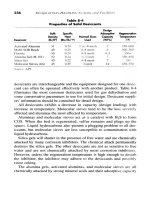
Head versus pressure
Figures
14
and
1-5
show the relationship between head and pressure
in a centrifugal pump moving liquids with different specific gravities.
There is more on this in Chapter
7.
The above graphic shows three identical pumps, each designed
to
develop
92.4
feet of head. When they pump liquids of different specific
gravities, the heads remain the same, but the pressures vary in
proportion
to
the specific gravity.
In
the graphic below (Figure
1-5),
these three pumps are developing
the same discharge pressure. In this case they develop different heads
inversely proportional
to
the specific gravity of
the
fluids.
Figure
1-5
-~
R8
sp.gr.
=
1.25 sp.gr.
=
1
.OO
sp.gr.
=
0.75
~~
~
Basic
Pump Principles
The concept of Head versus Pressure causes confusion between maintenance people
and the pump manufacturer. The maintenance technician reads his gauges recording
pressure in psi, and the pump manufacturer uses the term head. The term head is the
constant for the manufacturer.
A
pump that generates
90
feet of head can elevate
water, gasoline, caustic soda, and any liquid to a height of
90
feet. The manufacturer
doesn't know the ultimate service of the pump when he manufactures
it.
He only
knows that his pump will develop
90
feet of head. The psi reading
is
a function of the
conversion factor
2.31
and also the specific gravity. This is why
you
cannot specify
a
pump by the psi.
If
the maintenance engineer or mechanic wants to have an
intelligent conversation with the pump manufacturer, he must understand and use
the concept of 'head: This is also the reason that too many pumps are sold without
adequate gauges. It's somewhat like selling a car without a dashboard. There's more
information on this in Chapters
7
and
8.
Given the following information:
sp. gr. of water
=
1.0
=
0.70
sp. gr. of gasoline
sp. gr. of concentrated sulfuric acid
=
2.00
sp.gr.
of
sea water
=
1.03
A
pump capable
of
generating 125 feet
of
head would provide the
following pressures:
Pressure
=
(Head
ft.
x
sp.gr.)
/
2.31
Water:
Gasoline:
P=
1'25
OO7
=
37.8 psig
2.31
Conc. Sulfuric Acid:
P
=
1*25
2.0
=
108.2 psig
2.31
Sea Water
This pump (Figure
1-6)
is raising
the
liquid from the level in the
suction vessel
to
the level in the discharge vessel. This distance is called
the
Total
Head.
Know and Understand Centrifugal Pumps
ATMOSPHERIC
9
PRESSURE
I
L4
DISCHARGE
HEAD
I
SUCTION
I
DISCHARGE
HEAD
I
SUCTION
I
~~
Figure
1-6
The
total
head
is:
The work of the pump.
The measure
of
the pump's ability
to
raise the liquid
to
a
given
height.
The measure of the pump's ability
to
develop a given discharge
pressure.
The discharge elevation minus
the
suction elevation.
The discharge head minus
the
suction head.
The discharge head plus the suction lift.
The discharge absolute pressure reading minus
the
suction absolute
pressure reading.
Suction head
The suction head is the available head at the suction nozzle of the
pump.
Discharge head
The discharge head is the vertical distance from the centerline
of
the
pump (this would be the shaft on a horizontal pump)
to
the level in the
discharge vessel.
Suction
lift
Suction
lift
is negative suction head. It exists when the liquid level in
the suction vessel is below the centerline of the pump. The pump must
aspirate the liquid up from the suction vessel into the pump and then
Basic Pump Principles
ATMOSPHERIC
DISCHARGE
HEAD
I
.
I
I
N1CMY
.^.
Figure
1-7
push the liquid up into the discharge vessel. This pump (Figure
1-7)
is
said
to
be in suction lift.
In this case, the pump must
aspirate
or lift the liquid up from the
suction vessel into the pump and then
push
the
liquid up into the
discharge vessel. In this case the
total head
is
the
discharge head
plus
the suction lift. In all cases the
total head
is the work being performed
by
the
pump.
NPSH,
Net
Positive Suction
Head
Introduction
When someone turns on an electric light, the natural tendency is
to
look
toward the light and consider the shine.
We
tend not
to
think
about the electric wires and the current running through the light bulb.
Equally, when someone starts an industrial pump, the tendency is
to
look
toward the discharge piping and consider the pressure and flow.
We
tend not
to
think about the suction piping, or the liquid coming
into the eye of the impeller.
We
need
to
emphasize the necessity
to
consider what’s happening in the suction of the pump. This area is the
source of problems, and probably is responsible for about
40%
of all
pumps going into the shop
today.
This chapter is dedicated
to
NPSH, Net Positive Suction Head. NPSH
is what the pump needs, the minimum requirement
to
perform its
duties. Therefore, NPSH is what happens in the suction side of the
pump, including what goes on in the eye of the impeller. NPSH takes
into consideration the suction piping and connections, the elevation
and absolute pressure of the fluid in the suction piping, the velocity of
the fluid and the temperature. For the moment we can say that some of
these factors add energy
to
the fluid as it moves into the pump, and
others subtract energy from the fluid. There must be sufficient energy
in the fluid for the impeller
to
convert this energy into pressure and
flow. If the energy
is
inadequate we say that the pump suffers
inadequate NPSH.
In simple terms we could say that NPSH is the reason that the suction
nozzle is generally larger than the discharge nozzle. If there is more
liquid leaving the pump faster than the liquid can enter into the pump,
then the pump is being starved of liquid.
NPSH, Net Positive Suction Head
Think about
it
this way. When we see a magician pulling a rabbit out of a hat, in
all
probability there's a rabbit hidden
in
a secret compartment inside the top hat, or the
rabbit is hidden
in
the magician's coat sleeve. The rabbit does not appear
spontaneously. Isn't
it
interesting that magicians all wear long sleeved topcoats? They
always reach into a 'top hat' for the rabbit. When
I
see a magician pull a rhinoceros
magic. Likewise with a pump, the energy must be in the fluid for the impeller to
convert
it.
Equally,
if
your body requires more oxygen than the available oxygen in the
atmosphere, then you would be asphyxiated. There must be more oxygen available in
the air than the oxygen
you
consume.
from a frisbee, then maybe
1'11
believe in magic. There is illusion, but there is no
To
express the quantity of energy available in the liquid entering into
the pump, the unit of measure for NPSH is feet of head or elevation in
the pump suction. The pump has its NPSHr, or Net Positive Suction
Head Required. The system, meaning all pipe, tanks and connections
on the suction side
of
the pump has the NPSHa, or the Net Positive
Suction Head Available. There should always be more NPSHa in the
system than the NPSHr of the pump. Let's look at them, beginning
with what the pump requires:
Definition of NPSHr (required)
It is the energy in the liquid required
to
overcome the friction losses
from the suction nozzle
to
the eye of the impeller without causing
vaporization.
It
is a characteristic of
the
pump and is indicated on the
pump's curve. It varies by design, size, and the operating conditions.
It
is determined by a
lift
test, producing a negative pressure in inches
of
mercury and converted into feet of required
NPSH.
L
I
An
easy
way
to understand
NPSHr
is to call
it
the minimum suction pressure
necessary to keep the pumped fluid
in
a liquid state.
According
to
the Standards of the Hydraulic Institute, a suction lift test
is performed on the pump and the pressure in the suction vessel is
lowered
to
the point where the pump suffers a
3%
loss in total head.
This point is called the NPSHr of the pump. Some pump
manufacturers perform
a
similar test by closing a suction valve on a test
pump and other manufacturers lower the suction elevation.
Know and Understand Centrifugal Pumps
The definition of NPSHr may change in the future.
A
pump is in
a
definite state of cavitation with the 3% total head loss definition. Many
pump users want
a
more explicit definition of NPSHr, and higher
NPSHa safety margins
to
avoid inadequate NPSHa and cavitation
altogether.
The pump manufacturers publish the NPSHr values on their pump
curves. We’re saying that the NPSH reading is one of the components
of your pump curves. We’ll
see
this in Chapter
7
on Pump Curves. If
you want
to
know the NPSHr of your pump, the easiest method is
to
read
it
on your pump curve. It’s a number that changes normally with a
change in flow. When the NPSHr is mentioned in pump literature, it is
normally the value
at
the
best efficiency point. Then, you’ll be
interested in knowing exactly where your pump is operating on its
curve.
If you don’t have your pump curve, you can determine the NPSH of
your pump with the following formula:
Nl’SHy
=
ATM
+
PBS
+
HV
-
HvP
Where:
ATM
=
the atmospheric pressure at the elevation of the
installation expressed in feet of head.
Pgs
=
the suction pressure gauge reading taken at the pump
centerline and converted into feet of head.
Hv
=
Velocity Head
=
V2/2g where: V
=
the velocity of the
fluid moving through the pipes measured in feet per second,
and
‘g’
=
the acceleration of gravity (32.16 ft/sec).
Hvp
=
the vapor pressure of the fluid expressed in feet of
head. The vapor pressure is tied
to
the fluid temperature.
The easiest thing
to
do
is
to
get the pump curve from the manufacturer
because it has the NPSHr listed at different flows. Nowadays, you can
get the pump curve on the Internet with an e-mail
to
the manufacturer,
you can send
a
fax, or request the curve in the mail or with a local call
to
the pump representative or distributor. If you wanted
to
verify the
NPSHr on your pump, you’ll need a complete set of instrumentation: a
barometer gauge, compound pressure gauges corrected
to
the
centerline of the pump, a flow meter, a velocity meter, and
a
thermometer. Definitely, it’s easier
to
get the curve from your supplier.
Definition
N
PSHa
(ava
i
la
ble)
This is the energy in the fluid
at
the suction connection of the pump
over and above the liquid’s vapor pressure.
It
is a characteristic of the
system and we say that the NPSHa should be greater than the NPSHr
(NPSHa
>
NPSHr).
14
NPSH, Net
Positive Suction
Head
As
a general guide the NPSHa should be a minimum
10%
above the
NPSHr or
3 feet above the NPSHr, whichever is greater. Other books
and experts indicate that the NPSHa should be
50%
greater than the
NPSHr, to avoid incipient cavitation. Again, be prepared for stricter
definitions
to
NPSHr and higher safety margins on NPSHa.
The NPSHa is in the system. The formula is:
NPSHa
=
Ha
+
Hs
-
Hvp
-
Hf
-
Hi
Where:
Ha
=
Atmospheric head
(14.7
psi
x
2.31)
=
33.9
ft.
at sea
level.
See
Properties of Water I in this chapter that considers
atmospheric pressure at different elevations above sea level.
Hs
=
Static head in feet (positive or negative) of the fluid level
in the suction vessel
to
the pump centerline.
Hvp
=
the Vapor head of the fluid expressed in feet. It is a
hnction of the temperature of the liquid.
See Properties of
Water I1 in this chapter.
Hf
=
Friction head or friction losses expressed in feet in the
suction piping and connections.
Hi
=
Inlet head, or the losses expressed in feet that occur in
the suction throat of the pump up
to
and including the eye of
the impeller. These losses would not be registered on a suction
pressure gauge. They could be insignificant, or as high as
2
feet. Some pump manufacturers factor them into their new
pumps, and others don’t.
Also,
changes occur in maintenance
that may alter the Hi. If you don’t know the Hi, call it a safety
factor of
2
feet.
By
observing the system, you can calculate the NPSHa within a one or
two
point margin. The main idea is
to
be sure the NPSHa is greater
than the NPSHr of the pump. Remember that the NPSHa only deals
with the suction side of the pump. Let’s go back
to
that formula:
NPSHa
=
Ha
+
Hs
-
Hvp
-
Hf
-
Hi
1.
To
determine the Ha, atmospheric head, you only need observe the
vessel being drained by the pump. Is it an opened, or vented
atmospheric vessel? Or is
it
a closed and sealed vessel? If the vessel is
open, then we begin with the atmospheric pressure expressed in
feet, which is 33.9 feet at sea level. The altitude is important. The
atmospheric pressure adds energy
to
the fluid as
it
enters the pump.
For closed un-pressurized vessels
the
Ha is equal
to
the Hvp and
they cancel themselves. For a closed pressurized
vessel remember
that every
10 psia of pressure on
a
vessel above the vapor head of
the fluid will add
23.1 feet of Ha.
To
the
Ha,
we add the Hs.
2. The Hs, static head, is the static height in feet observed from the
level in the vessel
to
be drained
to
the centerline of the pump. If the
15
Know and Understand Centrifugal
Pumps
Properties
of
water
I
-
Atmospheric and barometric pressure
readinqs at different altitudes
Altitude Barometric Atmospheric Boiling
pressure pressure point
of
water "F
Feet Meters In. Hg. mm. Hg.
Psia
Feet water
-1000 -304.8 31
.O
788 15.2 35.2 213.8
-500
-152.4 30.5
775 15.0 34.6 21 2.9
0
0.0
29.9
760 14.7 33.9
21 2.0
+500 +152.4 29.4
747
14.4 33.3
211.1
+IO00 304.8 28.9 734 14.2 32.8 210.2
1500 457.2 28.3 71 9 13.9
32.1 209.3
2000
609.6 27.8 706
13.7 31.5 208.4
2
500 762.0 27.3 694 13.4 31.0 207.4
3000 91 4.4 26.8
68
1
13.2
30.4 206.5
3500 1066.8 26.3 668
12.9 29.8
205.6
4000 1219.2 25.8 655 12.7 29.2 204.7
4500 1371.6 25.4 645
12.4 28.8
203.8
5000 1524.0 24.9 633 12.2
28.2 202.9
5500 1676.4 24.4 620 12.0
27.6 201.9
6000 1828.8 24.0 61
0
11.8
27.2 201
.o
6500 1981.2 23.5 597 11.5
26.7 200.1
7000 2133.6
23.1
587
11.3 26.2
199.2
7500 2286.0
22.7
577
11.1 25.7
198.3
8000 2438.4 22.2
564
10.9 25.2 197.4
8500
2590.8
21.8
554
10.7 24.7
196.5
9000 2743.2
21.4 544 10.5 24.3 195.5
9500 2895.6
21
.o
533
10.3 23.8
194.6
10000 3048.0
20.6
523 10.1
23.4 193.7
15000
4572.0 16.9
429 8.3 19.2 184.0
level in the tank is 10 feet above the pump then the Hs is
10.
A
positive elevation adds energy
to
the fluid and
a
negative elevation
(suction
lift
condition) subtracts energy fiom the fluid.
To
the sum
of the Ha and Hs, we subtract the Hvp.
3.
The Hvp, vapor head, is calculated by observing the fluid
temperature, and then consulting the water properties graph in this
chapter. Let's say we're pumping water at
50"
F
(10"
C).
The Hvp
is
0.411
feet. If the water is 212" F
(100"
C)
then the Hvp is
35.35
feet. The vapor head is subtracted because it robs energy from the
fluid in the suction pipe. Remember that as
the
temperature rises,
more energy is being robbed from the fluid. Next, we must subtract
the Hf.
F1
16
NPSH, Net Positive Suction Head
Properties
of
water
II
-
Vapor Pressure
~~~ ~~
~~~_______
Specific Vapor Vapor
Temp.
'F
Temp.
"C
Gravity
60
OF Density Pres. psi Pressure*
Feet
Abs.
32
40
45
50
55
60
65
70
75
80
85
90
95
100
110
120
130
140
150
160
170
180
190
200
21 2
220
240
2 60
280
300
320
340
3 60
380
0
4.4
7.2
10
12.8
15.6
18.3
21.1
23.9
26.7
29.4
32.2
35.0
37.8
43.3
48.9
54.4
60.0
65.6
71.1
76.7
82.2
87.8
93.3
100.0
104.4
11
5.6
126.7
137.8
148.9
160.0
171.1
182.2
193.3
1.002
1.001
1.001
1.001
1
.ooo
1
.ooo
0.999
0.999
0.998
0.998
0.997
0.996
0.995
0.994
0.992
0.990
0.987
0.985
0.982
0.979
0.975
0.972
0.968
0.964
0.959
0.956
0.948
0.939
0.929
0.919
0.909
0.898
0.886
0.874
62.42
62.42
62.40
62.38
62.36
62.34
62.31
62.27
62.24
62.19
62.1 6
62.11
62.06
62.00
61.84
61.73
61.54
61.39
61.20
61.01
60.79
60.57
60.35
60.13
59.81
59.63
59.10
58.51
58.00
57.31
56.66
55.96
55.22
54.47
0.0885
0.1 21 7
0.1475
0.1 781
0.21 41
0.2563
0.3056
0.6331
0.4298
0.5069
0.5959
0.6982
0.81 53
0.9492
1.275
1.692
2.223
2.889
3.71 8
4.741
5.992
7.510
9.339
11.526
14.696
17.186
24.97
35.43
49.20
67.01
89.66
11 8.01
153.04
195.77
0.204
0.281
0.34
0.41
1
0.494
0.591
0.706
0.839
0.994
1.172
1.379
1.617
1.890
2.203
2.965
3.943
5.196
6.766
8.735
11.172
14.178
17.825
22.257
27.584
35.353
41.343
60.77
87.05
122.18
168.22
227.55
303.1 7
398.49
51 6.75
4.
The Hf, friction head, can be calculated, approximated, or
measured. The friction head can be calculated with the friction
tables for pipe and fittings. You can consult the Hazen Williams
formula, or the Darcy Weisbach formula mentioned in Chapter
8
of
this book. The friction head can
be
measured with gauges using the
17
Know and Understand Centrifugal Pumps
Bachus Custodio formula explained in Chapter
8.
In most cases, the
pump is relatively close
to
the vessel being drained by the pump. In
this case the Hf is probably negligible. Hf is subtracted because
friction in the suction pipe robs energy from the fluid as it
approaches the pump.
5.
The
Hi,
inlet head, is simply a safety factor of
2
feet. Some pumps
have an insignificant
Hi.
Other pumps have inlet losses approaching
2
feet. The Hi is
losses
to
the fluid after it passes the suction
pressure gauge and goes into the impeller eye. In a maintenance
fimction, you can't be precise about what's happening
to
the fluid
in this part of the pump. Just call it
2
feet.
Now let's apply the hints and the formula
to
the following system
figures and
we
can determine the NPSHa within one or
two
points.
The important thing is that the NPSHa of the system is greater than
the NPSHr of the pump. If the NPSHa should be inadequate, the
pump is being starved, becomes unstable and cannot perform its duties.
The inadequate NPSHa may lead
to
cavitation.
Remember that
NPSHa
>
NPSHr
This open system pumping water is at sea level (Figure
2-1).
Therefore
the Ha is
33.9
feet. The level in the tank is 15 feet above the pump
centerline,
so
the Hsl is 15 feet. The friction losses in the suction piping
give
us
2
feet. The water is
70"
F
so
the Hvp is
0.839.
The Hi is
a
safety
factor of
2
feet.
Hs
15
Open tank
Ha
=
33.9
I
n
70
?F
I
I
I
Hvp=0.839
I
Finiirp
3-1
n
18
1
.
NPSH, Net Positive Suction Head
NPSHa
=
Ha
+
Hsl -Hvp
-
Hf
-
Hi
NPSHa
=
33.9
+
15.0
-0.839
-
2.0
-
2.0
NPSHa
=
44.061
feet
The curve of the pump in this service should show an NPSHr of less
than
44
ft
at
the duty point. And the purpose of this pump is
to
drain
this tank, lowering its level. If we don't want inadequate NPSHa and
the possible resulting cavitation
to
start during the process we should
consider a second
Hs2
with the tank empty. The other factors remain
the same. At the end of
the
process, we have:
NPSHa
=
Ha
+
Hs2
-
Hvp
-
Hf
-
Hi
NPSHa
=
33.9
+
6.0
-
0.839
-
2.0
-
2.0
NPSHa
=
35.061
feet
To
avoid stress from inadequate NPSHa during the draining process,
we should consult the pump curve and be sure that the NPSHr is less
than
35
ft
at
the duty point.
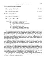
Now let's consider Figure
2-2.
This is
a
pump in suction
lift
draining
an opened tank that's
8
feet below the pump centerline. This pump is
installed high on a mountain
at
7,000
feet above sea level. The Ha is
26.2
feet. The Hsl is
-8.0
feet. The water temperature is
50"
F,
so
the
Hvp is 0.411. The Hf is
1
foot and the Hi is
2.0.
According
to
the
information:
NPSHa
=
Ha
+
Hsl
-
Hvp
-
Hf
-
Hi
NPSHa
=
26.2
+
(-8.0)
-
0.411
-
1.0
-
2.0
NPSHa
=
14.8
feet
The curve of the pump in this service should show a NPSHr of
less
than 14 feet
at
the duty point. The purpose of this pump is
to
drain this
tank down
to
14 feet below the pump without cavitating. Let's
consider a second static head,
Hs~,
of -14 feet. The other factors would
remain the same:
Open Tank
Ha
=
26.2
Temp.
=
50
*F
Flgum
2-2
Hvp
=
0.41
1
Ficlure
2-2
19
Know and Understand Centrifugal Pumps
NPSHa
=
Ha
+
Hs2 -Hvp
-
Hf
-
Hi
NPSHa
=
26.2
+
(-14.0)
-
0.411
-
1.0
-
2.0
NPSHa
=
8.8
feet
To
avoid problems with this pump during the process, be sure the
pump curve indicates NPSHr
less
than
8
ft
at the duty point.
Many processes
use
sealed tanks and reactor vessels. For example, in a
milk processing plant or a pharmaceutical plant, it’s necessary
to
prevent outside air from contaminating the sterile product. In
a
beer
brewery, you can’t let the gas and carbonization escape from the
process. In a closed un-pressurized vessel, the Ha is equal
to
the Hvp.
And because the
Ha
adds energy and the Hvp subtracts energy, they
cancel themselves. The formula
is
simpler:
NPSHa
=
Hs
-
Hf
-
Hi
The level in this sealed tank is 12 feet above the pump (Figure 2-3).
The Hsl is 12 feet. The purpose of this pump is
to
drain this tank
to
a
level
6
feet above the pump,
so
the Hsz is
6
feet. The Hf is 1.5 feet and
the
Hi
is
2
feet.
NPSHa
=
Hsl
-
Hf
-
Hi
NPSHa
=
12.0
-
1.5
-
2.0
NPSHa
=
8.5
The curve of
the
pump that drains this tank should register an NPSHr
Figure
2-3
NPSH, Net Positive Suction Head
of less than
8
feet at the duty point. And,
to
be sure that problems
don’t arise during the process, we could calculate the NPSHa at the
end of the process:
NPSHa
=
Hs2
-
Hf
-
Hi
NPSHa
=
6.0
-
1.5
-
2.0
NPSHa
=
2.5
feet
Now, it’s one thing
to
say
to
use
a pump with an NPSHr less than
2
feet. It’s another thing
to
find a pump with this design parameter, that
at the same time complies with the demands of the operation. Perhaps
it
will be necessary
to
modify
the
system
to
increase the Hs2, reduce the
Hf, or modify the pump
to
reduce the
Hi.
Other possible options are:
1.
Pressurize the tank with air or
a
gas compatible with the liquid and
process.
2.
Turn off the pump and drain the tank by gravity.
3.
Install a small booster pump that feeds the principal pump.
4.
Operate the pump at
a
slower speed.
5.
Survive the cavitation. (There’s a discussion on this later in the
book.)
As
we’ve said numerous times before in this chapter, the important
thing is that the NPSHa of the system is above
the
NPSHr of
the
pump
by
a
sufficient amount
to
avoid stress and possible cavitation. If the
NPSHa should be inadequate, there are ways
to
elevate it. Remember
from the formula that five elements compose the NPSHa. Two of those
elements, the
Ha
and the Hs, add energy
to
the fluid.
And
three
elements, the Hvp, the Hf, and the Hi, subtract energy from the fluid.
We must either increase the elements that
add
energy, or decrease the
elements that subtract energy.
To
increase the NPSHa:
1.
Raise the level in the tank if possible. This adds
Hs.
2.
Elevate the tank maybe with stilts. This adds
Hs.
3.
Maybe you can lower the pump. For example in many
thermoelectric plants, the fuel oil pumps
(#6
bunker fuel) are in a
pit. This would permit draining the tanks down
to
the ground and
still maintain
15
or
20
feet of NPSHa on the fuel
oil
pumps. This
adds
Hs.
4.
Pressurize the tank if possible. This adds
Ha.
5.
Reduce the drag
(Hf)
in the suction piping. Change
to
larger
diameter suction piping,
or
reduce the pipe schedule (change from
‘schedule
40
pipe’
to
‘schedule
20
pipe’ on the suction side).
Investigate changing the pipe material. For example
PVC
pipe, and
food grade Stainless, is rather slick on the ID. This reduces
Hf.
21
Know and Understand Centrifugal Pumps
6.
Reduce the losses
(Hf)
of the connections and fittings in the suction
piping. For wheel actuation valves, maybe globe valves could be
converted into gate valves. For quarter turn valves, butterfly valves
could be replaced with ball valves.
A
totally open butterfly valve still
has the post and wings in the flow path. Maybe convert short radius
elbows into long radius elbows. If you had
two
or three consecutive
elbows, maybe you could use a flexible
‘S’
connection. This reduces
Hf.
7. Eliminate some elbows. If the suction piping has multiple elbows,
you can bet that some of those elbows are canceling themselves, and
are not needed. This reduces
Hf.
8.
Lower the temperature of the fluid in the suction. This reduces the
Hvp.
If you cannot increase the NPSHa of the system, maybe you could
reduce the NPSHr of the pump, by:
Change
to
a pump with a larger suction diameter. For example,
convert a
1
x
2
x
8
pump, into a
2
x
3
x
8
pump. The larger pump
would have a reduced NPSHr. You need
to
keep the same impeller
diameter
(8
inch)
to
maintain the discharge head and pressures, but
you would be converting the
2
inch suction nozzle into
a
3
inch
suction nozzle. This would reduce the fluid velocity entering into
the pump, and therefore the
Hf
and
Hi.
Install
a
small booster pump into the suction piping. The booster
pump would have a reduced NPSHr for the system feeding
it,
and
the discharge head of the booster pump would increase the
Ha
to
the primary pump.
3.
Increase the diameter of the eye of enclosed impellers. This reduces
Hi.
4.
Ream out and polish the suction throat and pathway
to
the
impeller. This is normally the roughest casting inside the pump.
Center the suction nozzle on a lathe and open the diameter of the
pathway toward the impeller. This lowers the existing NPSHr
of
your pump, reducing the
Hi.
5.
Use
an impeller inducer. An impeller inducer looks like a corkscrew
device that fits onto the center hub of the primary impeller and
extends down the suction throat of the pump.
It
is actually a small
axial flow impeller that accelerates the fluid toward the primary
impeller from further down the suction throat of the pump. Some
inducers bolt onto the impeller and others are cast into the main
impeller. The inducer has a low NPSHr for the system feeding
it,
and
it
increases the
Ha
to
the primary impeller.
22
NPSH, Net Positive Suction
Head
6.
Convert
to
a
pump with
a
double suction impeller. Double suction
impeller pumps are for low NPSH applications.
7.
Use nvo smaller pumps in parallel.
8.
Use
a
larger/slowcr pump.
Inadequate NPSHa causes stress, vibration and maintenance
on
pumps
because there is not enough energy in the fluid for the pump to
perform its work.
As
you can
see
from the previous pages, the problems
lie in system design and proper operating principles.
When
the NPSHa
is below the NPSHr of the pump, the conditions are favorable for the
pump
to
go
into cavitation. Cavitation is
the
next chapter.
1-
"
-
-'
7
23
m