Know and Understand Centrifugal Pumps Episode 9 doc
Bạn đang xem bản rút gọn của tài liệu. Xem và tải ngay bản đầy đủ của tài liệu tại đây (562.56 KB, 20 trang )
Know and Understand Centrifugal Pumps
Types
of
misalignment
~~
There are
two
basic types
of
misalignment, angular and parallel. Within
each
of
these basic types
of
misalignment there are combinations
of
both. These are the most common combinations:
w
Vertical/angular misalignment (Figure
10-2
w
Vertical/parallel misalignment (Figure
10-3)
w
Horizontal/angular misalignment (Figure
104)
w
w
Horizontal /parallel misalignment (Figure
10-5)
Combined angular and parallel misalignment
1
Figure
10-2
and Figure
10-3
Side view
of
vertical/angular and vertical/parallel misalignment
Figure
10-4
and Figure
10-5
Top view
of
horizontal/angular and horizontal/parallel misalignment
Coupling with
Excentric Bore
Bore
Not
Perpendicular
to
Face
Figure
10-6
and Figure
10-7
Misalignment can be transmitted through the couplings and
couDlina faces.
144
Pump and
Motor
Alignment
Distorted Coupling Face
+-$$h-1-
~~
Figure
10-8
Misalignment
~
can be transmitted through the couplings and coupling faces.
Alignment techniques
There are a variety
of
shaft alignment procedures. The configuration
and size of the equipment determines the best alignment method.
Generally
the
driver or motor should be aligned
to
the pump. The
motor shaft centerline should be shorter and brought up
to
the pump
shaft centerline with shims or spacers. The pump is generally fixed and
attached
to
the
suction and discharge piping,
so
it is almost impossible
to
move. The volute casing aids in supporting the piping,
so
it
should
be fixed
to
a solid foundation without shims, jack bolts, or supports.
Verifying the alignment
of
running equipment is critical
to
maintain the
correct operation and reduce downtime.
Most established alignment procedures call for the use
of
precision dial
indicators
to
correct misalignment. Gaining popularity in industry is
laser alignment technology. We’ll cover this shortly. Among the most
popular methods
of
alignment are:
rn
Reverse Dial Indicator alignment.
rn
Rim and Face alignment.
rn
Straight Edge alignment.
rn
Laser Alignment.
Reverse dial indicator alignment
This is the most popular method used in industry today because the
investment in equipment is moderate and its effectiveness is proven.
This method uses
two
dial indicators, one on the pump shaft and the
other on the motor shaft.
Sometimes in practice the dial indicators are mounted on the couplings,
but it is best
to
mount and
fix
the indicators onto the shafts because the
couplings may be eccentric
to
the shaft centerlines. Rotate
the
shafts
and obtain the displacement readings. Project these readings graphically
or mathematically
to
the motor base
to
determine the adjustments
required, and the spacing shims under each foot.
Know and Understand Centrifugal Pumps
Rim and face alignment
This method is most useful when only one of the shafts can be rotated
for the alignment procedure, or when the
two
shaft ends
are
very close
to
each other. Obtain the displacement readings with
the
dial on the
rim
(OD)
of the coupling and the coupling face. Project these readings
mathematically or graphically
to
the motor base
to
determine the
required adjustments and shims for each foot. This method is not as
precise and may have a built-in error, if the coupling center is eccentric
from the shaft centerline.
Laser a
I
ig n men
t
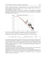
Laser alignment systems use a transmitter and receiver. The system has a
laser diode and a position sensor on a bracket mounted on one shaft
that emits a weak and safe radio-tagged beam of light. The light ray is
directed toward the other bracket on the other shaft
with
a reflecting
prism that returns the ray back toward the first bracket into the position
sensor eye.
One shaft is rotated
to
determine the vertical and horizontal readings as
in the other alignment techniques.
The shaft alignments are automatically entered into a small computer
that calculates the relative required movements needed at the motor
base
to
align the
two
shafts. See Figure
10-9.
Fiqure
10-9
146
Pump and
Motor
Alignment
General observations on the alignment process between shafts
1.
The alignment procedure should be repeated at various intervals
to
identify installation errors and compensate for equipment operation.
This is the way
to
assure long equipment life.
It
is recommended
to
go
through the alignment procedure and make corrections in the
following stages:
w
At Pump Installation:
Be
sure the motor shaft centerline is
below the pump shaft centerline
so
that it can be shimmed
upward. Make sure the motor mount boltholes have sufficient
play
to
allow for some lateral adjustment. Many pumps and
motor assemblies are shipped from the factory on a common
channel iron base plate. The manufacturer alleges that they are
already aligned at the factory. You need
to
verify and correct this
alignment in all cases.
w
Mer connecting the piping and accessories: Before starting the
pump, repeat the procedure after all associated connections have
been made. If there is a marked difference, the problem may be
pipe strain distorting the pump casing through the suction and
discharge nozzles. This situation should be resolved with the
installation contractor or pipe fitters. Not correcting this
situation is sure
to
bring future maintenance problems from
misalignment.
Hot
alignment: Allow the equipment
to
run for three or four
hours and come up
to
operating temperature, then shut-off the
pump and repeat the alignment procedure
with
the equipment
hot.
Running alignment: Mer
the
pump has been running for a
week or ten days, perform an alignment check
to
verify
that
the
equipment is not suffering pipe strain or binding from thermal
growth.
2.
The base and cement foundation should be examined
to
verify a
correct installation. The pump and motor assembly should rest on a
common base.
w
The base should be sufficiently strong
to
withstand the
machinery weight and minimize vibrations. Five times the mass
is the rule. If
the
pump, motor, and base plate weighs
1,000
lbs,
the foundation should weigh at least
5,000
lbs.
The base should be level and flat.
The base should be the proper size. This varies according
to
its
size and weight. It should have enough free adjacent space
to
perform maintenance, alignment and proper cooling.
147
Know and Understand Centrifugal Pumps
3.
The grout should be the correct type for the climate and application
temperature, speeds, and chemical nature.
w
Its function is
to
absorb the vibrations generated by the motor
and pump.
w
It should contain aggregate or epoxy.
w
It should be applied strictly according
to
manufacturer’s
recomrnenda tions.
w
It
should be inspected for fractures, crumbling, and separation
every six months
to
identi@ conditions affecting the equipment
alignment.
4.
Bases
w
The driver or motor shaft should be level and parallel with the
base.
Shims should be free of dirt and corrosion. They should be
replaced from time
to
time because they can become deformed
with time and weight.
w
Bases should be inspected for corrosion and corrected if
necessary.
w
5.
The Motor
w
During the alignment procedure, follow your plant
lockout/tagout procedure
to
prevent accidents.
w
Motor sleeve bearings require limiting
the
axial play.
w
Study the coupling manufacturer’s instructions
to
assure the
proper spacing between the faces. The spacing is relative
to
the
motor size.
6.
Dial indicators
w
During the alignment it is important
to
note the direction of
the
indicator movement. Beginning at
0.000
inches,
a
movement in
a clockwise direction is a positive reading.
A
counterclockwise
movement indicates a negative reading;
see
Figure
10-10.
Rotating
the
shaft and dial
360°,
the left lateral reading plus the
right lateral reading should equal the sum of the superior and
inferior readings.
The indicator readings at the end of the rotation should be the
same as the readings at the beginning of the rotation.
w
w
148
Pump and Motor Alignment
+
.015"
-
.010"
Fiaure
10-10
7.
Shims
w
Spacer shims should be made of
304
stainless steel, except with
chlorine and hydrochloric acid service. In these services,
use
Mylar shims
to
resist corrosion.
It
is best
to
use the thickest shim possible instead of numerous
thin shims, which can suffer fi-om compression. Never stack
more than
3
shims under an equipment foot.
w
Measure shims
to
verify their thickness and tolerance, especially
thin shims (those less than
0.005
inch).
w
Avoid the use of shims with the thickness stamped on the shim
face.
Use
shims large enough
to
completely cover the equipment
footprint.
w
Avoid rust, scratches, gouges, creases, indentations, hammer
blows and dirt.
Install the shims sliding them under the machinery footprint,
until contact is made with the anchor bolt. Then move the shim
back away from the bolt shaft
to
avoid interference with the
threads and
to
assure tolerance.
8.
Alleviate any possible pipe strain, a force imposed by the piping that
can distort the pump casing.
w
Pipe strain is normally caused by misalignment between the
piping and the pump nozzles, improper pipe supports, or
thermal expansion in the system.
w
Don't connect the piping
to
the pump until the cement base
and grouting is fully cured, and all foundation bolts are
tightened.
w
w
w
149
Know and Understand Centrifugal Pumps
€4
lncorrrect Correct
Figure
10-11
Bring
the
pipe
to
the
pump and adjust it
to
the
pump. Don’t
adjust the pump
to
the piping (Figure
10-11).
To
verify pipe strain, place
dial
indicators on the shaft and watch
for horizontal and vertical movement. Unite the flanges one at a
time continually observing the indicator readings. In general the
indicator readings should not exceed
0.002
inches (Figure
9.
Correct Soft Foot.
Soft
foot exists when one of
the
four machinery
feet is not level with the base. When
the
base bolts are tightened
with
soft foot, the effect can distort and misalign
the
pump casing.
To
check for
soft
foot, place a dial indicator onto the machinery
foot, and loosening
the
base bolt. If
the
indicator moves more
than
0.002
inches,
the
foot is
soft
and
it
should be corrected.
Go
through
the
same procedure on the remaining feet one at a
time.
10-12).
Fiqure
10-12
150
Pump and Motor Alignment
n
SOFT
FOOT
1
J7
SHORT FOOT
n
1
TOO MANY SHIMS
DISTORTED
I
BENT FOOT
c
DISTORTED
I
BENT FOOT
DIRT BETWEEN FOOT AND BASE
Fiaure
10-13
To
correct soft foot, place shims under the foot in the thickness
corresponding
to
the movement of the dial indicator.
If the foot inclines from either the outer or inner border, it will
always rise upon loosening the base bolt, and correct alignment
will be almost impossible.
It
will be necessary
to
re-machine
all
four feet
to
achieve parallelism between them.
10.
Check for indicator bar shaft deflection.
This deflection is due
to
the weight of the indicator dial.
Mount the dial indicators on the equipment in the same manner
and distance required
to
perform the alignment procedure.
Start straight up at the top of the shaft and rotate
180"
down
to
the bottom.
Note the indicator readings.
This deflection can be corrected easily during the alignment. For
example, with the indicators in the upper position on
the
shaft,
instead of starting at
0.000
inches, mark the positive value of the
deflection of the bar determined in the previous step, and then
rotate the shaft
180"
to
the bottom. Now the indicators will
read
0.000
inches.
151
Know
and Understand Centrifugal Pumps
I
BASE
0
.OOO"
t
I
I
-
0.003"
QUANTIFY THE
DEFLECTION
Figure
10-14
w
This same procedure can be used during the actual alignment
procedure
to
cancel bar deflection.
11.
Perform a Preliminary Alignment
w
Bring the equipment shafts into a reasonable state of alignment
with a machinist straight edge ruler and calibrated spacers before
using the dial indicators. When the shafts are far out of
alignment the dial indicators will make numerous revolutions
causing confusion.
It
is much better
to
perform a preliminary
alignment before applying the indicators.
w
Double check the distance between shafts with the recommen-
dation of the coupling manufacturer.
152
Pump and Motor Alignment
Fiaure 10-15
Equipment alignment sequence
Develop and practice the following alignment sequence.
Typical
Steps
Secure the pump
to
the base
Always begin with the thinnest shims
Use
the
minimum number of shims under any foot.
Pump
Motor
Fiaure 10-16
Cou
pl
i
ng
a
I
ig n men
t
Don’t
use
a flexible coupling
to
compensate for misalignment between
the pump and motor shafts. The purpose
of
the
flexible coupling is
to
compensate for temperature changes and
to
permit some axial
movement
of
the shafts without interference, while they transfer energy
fiom
the
motor
to
the pump.
There should be enough space between the coupling halves
so
that they
don’t touch should the motor shaft move forward toward the pump.
This space should also consider movement due
to
wear in the pump
thrust bearing. The coupling manufacturer specifies the minimum
153
Know and Understand Centrifugal Pumps
separation dimension between the coupling halves. You'll need a
machinist rule and thickness gauge or feeler gauge
to
perform a rough
alignment.
Before starting the alignment procedure, disconnect the coupling
halves. First, veri@
the
rough angular alignment inserting feeler gauges
at four points
(90")
around the faces between the halves. The
alignment is correct when the feeler gauge distance is the same at all
measured points.
The rough parallel alignment is done by placing the machinist rule
across both coupling rim surfaces in the upper position, lower position,
and both lateral points. The parallel rough alignment is correct when
the straight edge rests uniformly on both rims at all four positions.
Be
sure that the coupling rims are concentric with the pump and motor
shafts.
Don't start the pump until after completing all the previously
mentioned points, and any other specification mentioned in the
operation and maintenance manual of the pump provided by the pump
supplier. Not doing this could cause equipment damage and even
personal injury.
It
might even void the pump guarantee.
Bearings
Introduction
In order
to
understand bearings and their application in the world of
pumps, it’s best
to
consider some of the fundamentals and terminology
of bearings. Pump bearings have
two
general classifications: sleeve
bearings and rolling element bearings. The sleeve bearing is used mostly
on reciprocating rods and shafts and on some low rpm rotating shafts.
For rotating and centrifugal pump shafts the rolling element bearings
have almost displaced the older sleeve type bearings. The precision
rolling element bearing may have round balls, or rollers in the form of
spindles, cones, or needle rollers as the rolling elements. The rolling
elements move within an inner ring or race and an outer ring or race.
With pumps, the inner ring mounts onto, centers, and rotates with the
spinning shaft. The outer race is stationary and seated into a bore in the
bearing housing. This arrangement may be reversed in some special
duty pumps.
TYPE
DESCRIPTION
Ball Bearing
-
Conrad Deep Groove
Ball Bearing
-
Heavy Duty
Ball Bearing
-
Double Row, not self-aligning.
This is a single row bearing.
It
can
handle moderate radial and axial loads
from any direction.
This is also a single row design, but
it
has more balls in the assembly than the
Conrad bearing.
These bearings have two rows of balls
and can handle
50%
more radial load
than the Conrad type bearing.
Alignment
is
critical.
155
Know and Understand Centrifugal Pumps
TYPE
DESCRIPTION
Ball Bearing
-
Double Row, self-aligning These bearings have two rows
of
balls
and they can handle some shaft
misalignment. The axial or thrust
loading is limited.
Ball Bearing
-
Angular Contact
Roller Bearing
-
Cylindrical
Roller Bearing
-
Conical
Roller Bearing
-
Needle
These are single row ball bearings
capable of handling extreme axial or
thrust loads in one single direction only,
They are generally mounted in pairs to
handle any opposite axiallthrust loads.
This bearing is best suited to handle
radial loads. It doesn't work well with
axiallthrust loads. This bearing is
popular in electric motors.
These bearings are good handling
extreme axial
/
thrust loads in one
single direction only.
These are a type of roller bearing with a
roller diameter normally less than
.250"
and about a
1
:6
diameter to length
ratio, thus the term needle.
Roller Bearing
-
Spherical Symmetrical These spherical rollers are barrel shaped
and mounted in two rows rolling inside
a common inner and outer race
housing.
Each
type
of bearing is manufactured with different classifications of
play or internal tolerance. This play or tolerance refers
to
the distance
between the surface of the balls or rollers and the internal and external
raceways with axial or radial movement. The bearing tolerance is rated
with the codes
C1, C2, CN, C3, C4
and
C5. CN
code is
the
normal,
standard or average precision.
C1
is the most precise tolerance (the
tightest) bearing and
C5
is the least precision tolerance (the loosest)
bearing.
A
bearing without a stated code is normally a
CN
rating.
Standard pump bearings are mostly
C3
or
higher, slightly forgiving and
loose.
With this understanding of pump bearings, you can
see
that
it
is
not convenient
to
replace a
C3
pump bearing with a
C1
bearing.
Because of its strict tolerance, a
C1
bearing can handle
less
thermal
expansion and lubricant contamination that occur with normal pump
operation.
A
C1
bearing is less forgiving with thermal expansion and
contamination and will fail prematurely.
As
we've seen in previous chapters, the pump has basic head and flow
Bearings
specifications. The pump manufacturer installs bearings suited
to
the
pump’s design and general utilization. Based on this logistic, it’s always
best
to
use and replace the same type of bearing in a maintenance
function.
Bearing lubrication
Oil
lubrication
Oil is a popular pump bearing lubricating fluid. There are
two
classifications of lubricating oils: synthetic based and petroleum based.
Synthetic lube oils were developed principally
to
improve their high
temperature stability and overall temperature range. Petroleum based
oils are lower in cost and have excellent lubricating properties. Animal
and vegetable based lube oils are rarely considered for bearings because
they deteriorate, spoil and form corrosive acids.
As
a lubricating fluid, lube oil can be circulated, filtered, cooled,
heated, pumped, atomized, etc. For these reasons it’s more versatile
than grease. It’s convenient in severe applications involving extreme
temperatures and high velocities. The
oil
level and flow through high-
speed bearings is critical and these parameters should be monitored
appropriately. Because
oil
is a liquid, it is more difficult
to
seal and
contain inside the bearing chamber than grease.
Viscosity is the term used
to
indicate oil’s thickness or consistency. The
viscosity test is a measure of the fluid’s film strength. Excessive viscosity
can lead
to
the rolling elements skidding inside the bearing races. This
leads
to
raceway damage and overheating of the
oil.
Inadequate oil
viscosity can lead
to
premature bearing seizure from metal
to
metal
contact. Other properties
to
consider in selecting and using oil are:
corrosion protection additives, the pour point, the flash point, the
viscosity index, carbon residue,
and
the neutralization number.
Consider the loads imposed and operating temperatures of the bearings
when selecting the oil and its viscosity. Correct selection is essential for
long bearing life. The lubricant manufacturer publishes a data sheet
detailing the characteristics of their products. You should get this sheet,
study and understand the properties of the lube oil you’re considering
for use in your pump bearings.
Among oil’s advantages are:
Excellent friction reduction at high speeds.
Provides good lubrication at very high or low temperatures.
Good stability.
Heat transfer coefficient is
0.5
BTU/pound/degree Fahrenheit.
157
Know and Understand Centrifugal Pumps
Works well through heat exchangers with refrigerated water for
additional cooling in large high-speed bearings.
There are some disadvantages
to
using
oil,
including:
Difficult
to
seal and retain inside the bearing chamber requiring
frequent refilling.
Oil levels must be checked with more frequency as the temperature
rises.
Lower viscosity and more leaks as the temperature rises.
Grease
If you combine petroleum based or synthetic based oil with
a
suitable
thickening agent, you get grease. The thickening agent can represent
between
3%
and
30%
of the total volume of grease.
The amount of thickening agent and the oil’s viscosity will determine
the consistency or stiffness of the grease. For general industrial service,
popular thickening agents used
to
make grease are soaps of calcium,
sodium, aluminum, and lithium, and combinations of these. All greases
have certain characteristics, but they should not be categorized for
usage according
to
the thickening agent. For example, just because
grease is thickened with sodium soap doesn’t mean it is necessarily best
in a particular service.
No
particular grease can satis@ all requirements,
although considerable effort has been invested in developing a multi-
purpose lubricant.
Grease is selected for use in
a
pump bearing for its advantages,
including its resistance
to
dripping and running, and it’s easy
to
seal
and retain in the bearings. Grease also has some disadvantages. It is
subject
to
separation and oxygen decomposition.
It
is difficult
to
clean
and remove old grease from the bearing assembly.
Bearing lubrication in pumps
The majority of industrial pumps are designed with a horizontal shaft
assembly. Therefore, more pump bearings are lubricated with
oil
contained in the bearing chamber. Grease is preferred for bearings on
vertical pump shafts. Lip seals, labyrinth seals or mechanical seals
are used
to
seal the bearing housing where the spinning shaft
passes through, keeping any contamination out of the bearings and
holding the lubricant into the housing. Seals are discussed later in this
chapter.
Correct oil level is critical. Consult the owner’s manual.
As a general
guideline, the oil level should be half way up the lowest ball or roller in
the bearing assembly.
Too
much, or
too
little oil will lead
to
premature
Bearings
RADIAL
BEARING
ENTRANCE
FORCED LUBE
OIL LEVEL
INDICATOR
EXTERNAL
LUBE BOlTLE
Figure
11-1
~~
i\
bearing failure, which leads
to
coupling and motor failure on the power
end, and mechanical seal failure on the wet end.
Oil
mist systems exist
to
provide continuous minute quantities of
oil
fog
to
the rolling assembly. These systems normally employ an
additional pump, atomizer, and filter. These systems are gaining
popularity in hot applications, or with heavy thrust and radial loading.
The
oil
fog is sprayed into the bearing chamber with either a wet sump
or a dry sump. The wet sump method provides the bearings with a bath
(the liquid oil level) and a fog spray.
See
Figure
1
1-1.
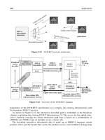
The dry sump method of
oil
misting has no liquid
oil
contained in the
bearing chamber. Instead, the entire chamber is filled with the atomized
oil fog.
See
Figure
11-2,
next page.
Both the dry sump and wet sump method of oil misting have
a
slight
positive pressure in the bearing housing. This prevents contaminants
and even humid air from entering the bearing chamber.
Bearing failure
Pump operators and pumping systems are plagued by unexpected
premature bearing failures. Even if the cost of the bearing is small, the
159
Know and Understand Centrifugal Pumps
Fiaure
11-2
direct and indirect associated costs of its failure and replacement can be
substantial. For example, a pump bearing may only cost
$20.00
to
buy,
but its failure could also take out a mechanical seal. Now, besides the
cost of the bearing and mechanical seal, is the cost of disassembly and
reassembly of the pump. And, there
will
be other replacement parts
to
change although they may or may not have failed. Some of these would
be
the
casing gaskets, pipe flange gaskets, set screws, snap rings, clip
rings, wear bands, shims, oil seals, nuts and bolts, not
to
mention the
oil or grease lost. Then there is the time dedicated
to
the repair, which
is also the time lost from production.
Most often,
the
bearing or the lubricant is blamed for the failure. This
is like blaming the
hse
for an electrical failure. The failure is most likely
a result of some abnormal operating condition, or lack of proper
maintenance. In short, something causes the bearing
to
fail
prematurely.
Among the most common causes of premature bearing failure are the
following:
1.
Improper mounting.
Improper procedure when mounting
the
bearing on the shaft is one
of the most common causes of premature failure. Roller bearings
and ball bearings are precision devices, and correct installation
160
Bearings
practices are very important. They must be stored correctly and
handled correctly
to
give good service life. The shaft and housing
dimensions must be within limits specified by the bearing
manufacturer. Shaft
to
motor alignment is also critical.
You should strictly follow correct and acceptable practices when
removing the
old
bearing and installing
the
new one. Cleanliness is
the order of the day. You’ll need a clean work area, clean hands, and
cleaning cloths without
fuzz,
lint, or strings.
So
much of premature
bearing failure is the direct result of not observing these basic
concepts.
2.
Vibration Brinelling
Maintenance people are not normally familiar with vibration
brinelling, but this is also a common cause of failure. The brine11
marks themselves are small, even invisible indentions in the bearing
raceway. They result fiom vibrations or shocks originating outside
the bearing. Common sources would be cavitation, bent shafts, un-
balanced rotary assemblies; shock thrust loads, slapping v-belts, etc.
These vibrations cause the balls
and
rollers
to
jam into the raceways
causing the imperceptible indentations.
The
races eventually take on
the appearance of corduroy cloth or a washboard effect. It’s like
driving a car at high speed over a rough roadway. The surfaces of
the balls and rollers begin breaking away, thus destroying
the
bearing.
All
bearings coming out of service should be disassembled
to
examine the internal rotary and stationary surfaces.
3.
Dirt and Abrasion
Careless handling during storage and assembly damages a
lot
of
bearings and lets dirt get in, thus leading
to
premature failure. Dirt,
sand and dust contamination between the balls and races of a new
bearing can start a round of ‘false brinelling’, ruining the bearing
even before it
goes
into service. Dirty sweaty hands, damp cloths,
humid air and even the morning dew can start a rusting process that
will destroy a new bearing. Bearings should be kept clean. Some
studies indicate that more than
90%
of all bearing failure is
attributable
to
abrasive dirt entering the bearing before and during
its installation. A grain of dirt or sand trapped between the ball and
race of a precision bearing has the same effect as running a race with
a
rock stuck in your shoe.
Sleeve bearings on some older, slower, larger pump shafts can
withstand dirt contamination better than ball and roller bearings.
This is because the tolerances are not
so
strict with sleeve bearings,
the surface area of contact is greater, and the lubricant flushing
action is better. The sleeve bearing material of construction is
161
n
Know and Understand Centrifugal Pumps
normally softer than the shaft material, and abrasives can be
absorbed into or imbedded into the bearing material without
destroying
it.
This is certainly not the case with precision ball and
roller bearings.
Bearings should not be left exposed overnight. Coat bearings
with clean oil and cover them with clean oil or wax paper.
Clean the internal bearing housing and shaft seat before
installing the bearing.
rn
Clean and paint all un-machined internal surfaces inside the
bearing housing with oil resistant paint.
Do
not spin a new bearing by hand or with compressed air. This
introduces dirt and grit and causes
it
to
imbed into the
protective grease.
w
4.
Inadequate Lubrication
Inadequate means not enough lubricant, and it means the wrong
type of lubricant. If the lubrication is insufficient, the bearing suffers
short life from
too
much friction, high heat, and metal-to-metal
contact between rolling and stationary elements. For horizontal
shafts, the proper oil level is: half way up the lowest ball or roller in
the bearing assembly. Some pumps have a site level indicator
showing the
oil
level inside the bearing chamber. It is recommended
that you install these indicators if your pumps don’t have them.
Teach the operators and mechanics
to
pay attention
to
the
indicators.
As
for greases, lithium based grease is for pumps.
Polyurea based grease is for electric motors. If these
two
greases are
mixed or confused, it will lead
to
premature pump bearing failure.
5.
Excessive Lubrication
Too
much lubrication is as damaging
to
bearings as insufficient
lubrication. It also leads
to
overheating. When the oil level is
too
high, the bearing balls and rollers crash into the oil pulling in air
and bubbles leading
to
foaming. The foam and froth mixed with air
cannot remove the heat.
In cold clii
The air poi
heat is not lost througn tne wind
from escaping.
nates, many homes and businesses
use
double and
tric
cket between double and triple pane windows serves
tl
.
.
.
.
.
. .
. . . .
.
)le
pane windows.
o
insulate
so
that
ows. LiKewise, air
bubbles
in oil prevent the heat
Bearings
The foam and froth in the bearing oil, increases the volume and
artificially raises the oil level, which leaks through the seals. When
enough has leaked
to
stop foaming, the air bubbles leave the oil
resulting in inadequate oil levels.
Too
much friction heat and failure is
the result.
Bearing maintenance
Cleaning bearings and relubrication
A
lubricant, either oil or grease, should always be present in the
bearings in small quantities. If not, the life of the bearing will be
compromised by damage
to
the bearing surfaces. This damage can be
avoided with proper cleaning and relubrication. The intervals for
cleaning and re-lubing the bearings are generally long periods.
It’s easy
to
see
when a bearing needs oil. Check the oil site level
indicator. It’s different with grease. It’s impossible
to
determine when a
bearing needs more grease. This is because the grease in the bearing
does not suddenly lose its lubricating properties. These properties are
lost gradually over time. Previous operating experience (history) is a
good guide
to
determine when
to
add more grease. The intervals
depend on the grease properties, the size and design of the bearing, the
operating speed, the temperature, and humidity.
In important process pumps, the grease in
a
bearing should be changed
every 12
to
18
months. This will assure a reliable pump operation and
service because time alone causes certain deterioration in the
lubricating ability of grease.
The intervals for cleaning and re-lubricating bearings should be more
frequent if water or moisture is able
to
enter into the bearing chamber.
Bearings can become contaminated from rain, hose-downs, pumps
located under dripping equipment, dew, fog and condensation.
Entrance points could be through inadequate, worn or failed shaft
seals,
the breather cap, and the lube
oil
fill
port. Be sure the new grease or
oil
is not contaminated.
Grease is normally injected through a port called a zerk (or zirk) fitting,
or by removing the bearing end cover or housing cap. When injecting
grease mechanically or hydraulically, remember
to
open the drain or
expel port. The new grease will expel the
old
grease under pressure.
Also
remember
to
close the drain port afterward. The amount of grease
to
be added is a function of the housing size and design and the
size
of
the bearing. The grease should completely impregnate the bearing and
fill the housing about 25%
full.
Too
much grease leads
to
overheating.
163