wireless hacking projects for wifi enthusiasts phần 8 doc
Bạn đang xem bản rút gọn của tài liệu. Xem và tải ngay bản đầy đủ của tài liệu tại đây (1.68 MB, 37 trang )
Budget calculation. (A good online calculator can be found at www.afar.net/RF_calc.htm and
www.qsl.net/pa0hoo/helix_wifi/linkbudgetcalc/wlan_budgetcalc.html)
Path loss, the amount of loss in dB that occurs when a radio signal travels through free space (air),
is also known as Free Space Loss (FSL). FSL can be calculated using the following formula:
FSL (isotropic) = 20Log10 (Freq in MHz) + 20Log10 (Distance in Miles) + 36.6
Additional factors you should consider when determining your link’s requirements:
■
Radiation pattern/propagation angle The propagation angle is given in degrees and
denotes how much area in degrees an antenna broadcasts its signal. Example: Vertical angle
= 45 degrees, Horizontal angle = 7 degrees. Search the Internet for various antenna manu-
facturers to find examples of Smith charts that represent various propagation angles.
■
Polarity All antennas have a “pole” (short for polarity), which can be horizontal, vertical,
or circularly polarized. Polarity indicates the angle of the RF wave’s propagation in reference
to an H/V/C plane.You must insure that all Wi-Fi systems you want to communicate with
have antennas on the same pole.The difference in H/V poles (if for example, one antenna is
horizontally polarized and the other is vertically polarized) is a loss of 30 dB.
■
Vertical/horizontal beam width This is the angle of the RF “beam” referenced to the
horizontal or vertical plane.Typically, the higher the gain, the more focused (narrow) the
beam. Example: A 24 dBi antenna commonly has an 18-degree beam width, vs. a 9 dBi
antenna, which will have a 45- to 60-degree beam width.
■
Fresnel zone The Fresnel zone is the propagation path that the signal will take through
the air.The Fresnel zone can be determined using the formula below.The Fresnel zone is
important when installing Line-of-Site equipment, because if the Fresnel zone or any part
of it is obstructed, it will have a direct and negative effect on the system connectivity.
Fresnel Zone Calculation = 72.1 * SqrRoot(Dst1Mi * Dist2Mi / Freq (in GHz) * Distance-in-Miles
You can find a good online Fresnel zone calculator at www.radiolan.com/fresnel.html.
■
Front-to-back ratio An antenna’s front-to-back ratio is typically given in dB and denotes
how much signal is projected behind the antenna, relative to the signal projected in front of
the antenna (in the main lobes).The lower the front-to-back ratio, measured in dB, the
better.The reason is that you don’t want excessive signal propagating from the rear of the
antenna.
■
Link Margin The Link Margin, sometimes called System Operating Margin (SOM), is the
minimum difference between the received signal (in dBm) and the sensitivity of the receiver
required for error-free operation. In many systems, this is also referred to as the Signal-to-
Noise-Ratio (SNR).
Table 10.3 lists Fade Margins for various link distances.
www.syngress.com
Antennas • Chapter 10 235
308_WiFi_Hack_10.qxd 9/30/04 6:50 PM Page 235
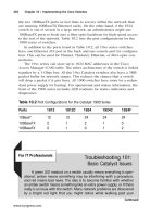
Table 10.3 Fade Margins for Various Link Distances
Distance (Miles) Conservative Fade Margin (dB)
0.5 4.2
1 7.5
2 10.8
3 12.75
4 14.1
5 15.2
10 18.5
15 20.4
In many newer radios, a Signal to Noise Ratio (SNR) specification is used instead of the RSSI
reading/measurement. Motorola’s 5 GHz Canopy system requires only 3 dB SNR to achieve connec-
tivity, while Alvarion’s EasyBridge 5.8 GHz system expects a minimum 10 dB SNR for connectivity.
Several good Web sites provide calculators for Fresnel Zone, Fade Margin, and Path Loss:
■
www.zytrax.com/tech/wireless/calc.htm
■
www.dataradio.com/mso/tsan002rf.xls
■
www.andrew.com/products/antennas/bsa/default.aspx?Calculators/qfreespace.htm
NEED TO KNOW…THE BIGGER THEY ARE, THE FARTHER THEY CALL
Size does matter! It may be necessary to increase the size of your antenna if you find that
you can’t quite get the desired distance or throughput from your link. Remember the “6 dB”
rule when thinking about antennas (size), propagation distance, and path loss. The rule
states that each time you double the distance from transmitter to receiver, the signal level
decreases by 6 dB.
Attenuation in Cables, Connectors, and Materials
Attenuation is the reduction in signal due to cable length, connectors, adapters, environment, or
building materials. Often, indoor wireless systems will suffer extreme attenuation due to metal cross
members or rebar within walls. It is important to consider the type of building materials used for
either indoor systems or systems where client antennas are mounted indoors while AP antennas are
outdoors at a distance. It is also important to take the figures for cable and connector loss into
account when calculating your link budget.
Table 10.4 lists common building materials and the expected loss in dB.
www.syngress.com
236 Chapter 10 • Antennas
308_WiFi_Hack_10.qxd 9/30/04 6:50 PM Page 236
Table 10.4 Attenuation Factors for Various Materials
Material Attenuation Factor/dB Loss
Plasterboard wall 3 dB
Glass wall with metal frame 6 dB
Cinder block wall 4 dB
Office window 3 dB
Metal door 6 dB
Metal door in brick wall 12.4 dB
The most common cables used in unlicensed wireless include:
■
RG-58 Commonly used for pigtails and is not recommended for long runs. Loss at 2.4
GHz per 100 feet = 24.8 dB.
■
LMR 195 Identical in gauge to RG 58, but with less loss. Loss at 2.4 GHz per 100 feet =
18.6 dB.
■
LMR 400 Used most commonly for antenna runs over 6 feet. Loss at 2.4 GHz per 100
feet = 6.6 dB.
■
LMR 600 The best, but also the most expensive cable. Loss at 2.4 GHz per 100 feet =
4.3 dB.
The loss quoted for any cable specification is generally per 100 feet.The loss factor is important
to remember when installing outdoor systems. For both cables and connectors, the loss factor is com-
monly listed as “insertion loss.” A good online cable loss calculator can be found at www.timesmi-
crowave.com/cgi-bin/calculate.pl.
Figures 10.7 through 10.11 are examples of connector types used in unlicensed wireless systems.
In most cases, it is assumed that the loss per connector is between .2 and 1.0 dB. Many people use .5
dB of loss per connector as a general rule of thumb. If a connector is suspect and produces more loss,
it is either of poor design or is faulty.
Antennas • Chapter 10 237
Figure 10.7 “N” Type Figure 10.8 SMA
www.syngress.com
308_WiFi_Hack_10.qxd 9/30/04 6:50 PM Page 237
System Grounding and Lightning Protection
Since an antenna is a metal object with a corresponding wire connection and is elevated several feet
in the air, it unfortunately makes an excellent lightning rod. It is always recommended that you use
both an earth ground and a lightning arrestor when installing antennas outdoors.The earth ground
should be connected to the antenna mast and the antenna tower to ground electrical charges (light-
ning). It is also recommended to use a lightning arrestor to protect radio equipment.The insertion
loss of a good lightning arrestor is commonly a maximum of 1.5 dB.
Figure 10.12 shows a typical lightning arrestor.
www.syngress.com
238 Chapter 10 • Antennas
Figure 10.9 MMCX
Figure 10.10 TNC
Figure 10.11 Reverse Polarity (R/P) TNC
308_WiFi_Hack_10.qxd 9/30/04 6:50 PM Page 238
WARNING: HARDWARE HARM
The labeling on the lightning arrestor denotes the antenna port connection and the equip-
ment (radio) port connection. Connecting the device in reverse may result in damage to
equipment and systems. It is also quite probable that the system will not work or perfor-
mance will be severely degraded.
The lightning arrestor should be located between the radio equipment and the antenna. Figure
10.13 is an example of a small unidirectional antenna with jumper cable plus a lightning arrestor and
pigtail assembly.This could be mounted on a pole, on the side of an eave, or in conjunction with an
outdoor box containing the radio.
www.syngress.com
Antennas • Chapter 10 239
Figure 10.12 Common Lightning Arrestor for 2.4 GHz
Figure 10.13 Lightning Arrestor Mounting Scenario
308_WiFi_Hack_10.qxd 9/30/04 6:50 PM Page 239
WARNING: HARDWARE HARM
It is always recommended that proper grounding techniques and lightning protection
devices be used when installing any antenna system outdoors. Always use caution when
installing antennas, especially when using extended masts or building tower sections.
Building a Coffee Can Antenna
If you’d rather not purchase antennas from one of the many commercial options, there are many Do-
It-Yourself designs available. For those of you who are interested in experimenting, we’ll start with
building a coffee can antenna.The coffee can antenna hack we’ll be describing here will provide up
to 11 dBi of gain at 2.4 GHz.
Preparing for the Hack
Before constructing any antenna, there are two important formulas you need to know.The
first is a Frequency/Wavelength formula. For our purposes, we’ll use Megahertz instead of
Gigahertz.
This tells us the wavelength for our coffee can antenna. For example, if we use 2.45 GHz (the
middle of 2.4 GHz band), we get a wavelength of = .4016 feet (984/2450).
The materials required for this hack are:
■
Garden-variety coffee can as shown in Figure 10.14 (Folgers or Maxwell House will do).
The best cans will be 3 to 3.5 inches in diameter, as long as possible.
■
1.2” brass rod or 12-gauge solid core electrical wire
■
Type “N” bulkhead connector
■
Four very small nuts and bolts (long enough to extend through the connector and can)
240 Chapter 10 • Antennas
Figure 10.14 Coffee Can
www.syngress.com
308_WiFi_Hack_10.qxd 9/30/04 6:50 PM Page 240
Performing the Hack
To perform the hack:
1. Drill a 1/2” hole, for the type “N” connector.
If your can has a 3” diameter, the hole should be 3.75” from the bottom of the can.
If your can has a 3.25” diameter, the hole should be 2.5” from the bottom of the can.
If your can has a 3.5” diameter, the hole should be 2.07” from the bottom of the can.
If your can has a 3.75” diameter, the hole should be 1.85” from the bottom of the can.
If your can has a 4” diameter, the hole should be 1.72” from the bottom of the can.
2. Tin the bulkhead connector by applying a light coat of solder to the “inside” center pin (the
opposite side of where the cable is connected).
3. Cut a brass rod 1.2” in length and solder the connector to the brass rod.You can also use
solid core 12-gauge electrical wire. Figure 10.15 shows “helping hands,” which can be useful
when you need an extra set of hands for soldering. Figure 10.16 shows a completed element.
4. Insert the bulkhead connector into the can (the wire/rod portion goes in the can; the other
side, where the cable attaches, goes outside the can). Use the four bolts/nuts to secure the
connector in place.You may need to drill some small pilot holes in the can to get the bolts
through. Figure 10.17 shows a completed coffee can antenna.
www.syngress.com
Antennas • Chapter 10 241
Figure 10.15 “Helping Hands” Helpful when Soldering Wire and Connectors
308_WiFi_Hack_10.qxd 9/30/04 6:50 PM Page 241
The coffee-can side of the pigtail is an “N” connector, while the other side (for connecting to the
radio) is an SMA connector. Various types of connectors may be used depending on the connector
interface required by the PC card or subscriber unit.
NEED TO KNOW…SAVE THE JUMPER/PULL THE PIGTAIL
It is important to remember that most wireless APs will require a short cable commonly
referred to as a “pigtail” to interface between the antenna and the AP. This cable is usually
3”–6” in length with connectors on each end. There are several types of connectors used on
commercial APs and client cards. It is also sometimes necessary to use a short “jumper” cable
between the lightning arrestor or outdoor enclosure and the antenna. These cables should
be 6” to 10”. Figure 10.18 shows a common 10” pigtail with “N” Connector and MMCX
(PCMCIA) Connector. Figure 10.19 shows a 6” N-to-N jumper used between the antenna and
lightning arrestor.
www.syngress.com
242 Chapter 10 • Antennas
Figure 10.16 The Completed “Waveguide” Element
Figure 10.17 The Completed Coffee Can Antenna
308_WiFi_Hack_10.qxd 9/30/04 6:50 PM Page 242
Under the Hood: How the Hack Works
Lightning arrestors are basically voltage “redirectors” that really do not eliminate all electrical charges.
However, the standard 1/4 wave stub lightning arrestors from PolyPhaser are the best type for unli-
censed wireless in the 2.4 and 5 GHz frequency range. It is important to remember that lightning
arrestors are rated for frequency. Always check the specifications for lightning arrestors prior to pur-
chase and installation.
Troubleshooting Common Antenna Issues
It is often necessary to troubleshoot systems when performance falls short of expectations.The fol-
lowing tips will help you determine what the problem(s) might be with poor signal quality, poor
throughput performance, or a combination thereof.
When there is no reception, and power and system connections appear correct, some possible
problems could be:
www.syngress.com
Antennas • Chapter 10 243
Figure 10.18 A Common 10“ Pigtail with “N” Connector and MMCX (PCMCIA) Connector
Figure 10.19 A 6“ N-to-N Jumper Used between the Antenna and Lightning Arrestor
308_WiFi_Hack_10.qxd 9/30/04 6:50 PM Page 243
■
Antenna polarity is reverse of distant antenna
■
Lightning arrestor is installed backward
■
RF cable has incorrect termination or excessive loss
Poor signal strength on wireless monitor or radio LED indicators could be because:
■
Connectors not tight
■
Cables poorly terminated
■
Lightning arrestor backward
Intermittent signal fluctuations during transmission and reception could be the result of:
■
Interferences from friendly or phantom transmitters or equipment (microwave, cordless
phone, other APs)
■
Multiple antennas on the same polarity—try switching one or alternating antennas to the
cross (reverse) pole
The Future of Antennas
Recently, there have been some exciting developments in the field of antenna technology, specifically
related to Wi-Fi and the coming WiMax systems.Airgo Networks Inc. (www.airgonet.com) has
developed antenna technology based on the yet-to-be-ratified 802.11n MIMO standard.The MIMO
acronym stands for Multiple Input/Multiple Output, and uses multiple antennas to increase the range
of 802.11 wireless systems. It is designed to increase speed, improve reliability, and reduce interference.
These systems (claim to) provide four times (4X!) the coverage area of standard antennas.
Array COM is another vendor that has developed so-called “smart” antenna systems.These smart
antenna systems are capable of remote tuning and/or automatic gain and beam width adjustment based
on sampled conditions.The following is a list of these antenna types and a brief description of each:
■
Dual polarity antennas Antennas that are capable of either horizontal or vertical polarity.
The antennas typically have separate connectors for both H and V polarity It is not possible
to operate at both polarities simultaneously.
■
Multi-gain and variable beam, tunable antennas A multiple gain, variable beam
antenna is capable of operating at various gains, given a desired beam width.Typically, the
higher the gain, the more focused the beam width.A common antenna of this type is a
TelTek 2304–3.The antenna has settings for 60, 90, 120, beam width.The gain figures rise as
the beam width decreases. Example: 24 dBi gain @ 60 degrees, 12 dBi @ 90 degrees.
■
“Smart” antennas Antennas that adjust automatically to the performance characteristics
of the system.
www.syngress.com
244 Chapter 10 • Antennas
308_WiFi_Hack_10.qxd 9/30/04 6:50 PM Page 244
Summary
In this chapter, we reviewed RF Math (rule of 10s and 3s), antenna types, FCC regulations, polariza-
tion, Fresnel zones, connector types, and safety issues (grounding and lightning arrestors). We also
took you through the steps to build your own coffee can antenna.
Selecting the right antenna for your project is one of the most important steps of any wireless
deployment. Antennas do not actually increase the system power. Rather, they merely “reshape” the
RF pattern and focus the energy in a particular direction. Antennas are rated with various “gains,” as
measured in decibels (dB). Use good cables and connectors to help defend against unnecessary signal
loss.Thicker, more expensive cables often have the lowest amount of loss.
Always be sure to pay special attention to safety issues. As outdoor mounted antennas are at risk
of lightning strikes, make sure to use a lightning arrestor and proper grounding for both your antenna
and mast. Be sure to use safety cables for your antennas and antenna masts to make sure that nobody
is injured below if a mast were to accidentally come loose or fall.
www.syngress.com
Antennas • Chapter 10 245
308_WiFi_Hack_10.qxd 9/30/04 6:50 PM Page 245
308_WiFi_Hack_10.qxd 9/30/04 6:50 PM Page 246
Building Outdoor
Enclosures and
Antenna Masts
Topics in this Chapter:
■
Building Outdoor Enclosures
■
Building Antenna Masts
Chapter 11
247
308_WiFi_Hack_11.qxd 9/30/04 5:23 PM Page 247
Introduction
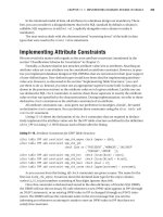
The design and implementation of outdoor wireless networks is a challenge that spans many disci-
plines, from programming, to radio frequency (RF) engineering, to carpentry and metal work. As
with any multifaceted project, the final product is only as strong as its weakest link, making even the
most mundane detail just as critical as the next. With thoughtful planning and careful implementation
of every detail, from the choice of enclosure to the type of fastener used to secure your antenna, you
can take steps to help ensure your outdoor wireless networks’ dependability regardless of weather con-
ditions.
In this chapter you will learn how to:
■
Choose the appropriate enclosure for your needs
■
Select proper hardware
■
Secure the communications equipment inside the enclosure
■
Secure the enclosure itself
■
Construct a sturdy mast for your antenna
■
Protect your equipment from lightning strikes
Building Outdoor Enclosures
In my years of building community wireless networks in San Diego, my fellow wireless enthusiasts
and I have been through many different iterations of outdoor wireless equipment enclosures.These
different enclosures span from the infamous “Tupperware Enclosure” to a $70.00 turnkey box made
to accept the wireless gear of your choice. Between these two extremes exists a category of enclo-
sures, which meets the needs of the application yet still require some extra attention to bring all of
the pieces together.
NEED TO KNOW…TURNKEY ENCLOSURES
“Turnkey” enclosures are made to house specific equipment, to be secured in a specific way,
and to be ready to use right out of the box. While these types of enclosures are usually high
in quality and easy to install, they are expensive and restrictive regarding what types of
equipment can be installed in them and where and in what manner they can be installed.
For these reasons, many of the enclosures used in the SoCalFreeNet networks are of the
variety discussed in the following pages.
www.syngress.com
248 Chapter 11 • Building Outdoor Enclosures and Antenna Masts
308_WiFi_Hack_11.qxd 9/30/04 5:23 PM Page 248
Building Outdoor Enclosures and Antenna Masts • Chapter 11 249
Preparing for the Hack
Building an outdoor enclosure can be a very simple procedure involving plastic food containers with
holes poked in them, or it can involve elaborate fabrication techniques requiring thousands of dollars
worth of equipment. In the following pages, we attempt to strike a balance between these two
extremes, constructing a durable enclosure that meets all of your needs while keeping the necessary
time and equipment investment to a minimum.The following are some of the basic tools required to
perform this hack:
■
A basic tool set (wrenches, pliers, screwdrivers)
■
A drill with an assortment of fractional-sized drill bits
■
A tape measure
■
A hacksaw
■
Weatherproof silicone sealant
Additional tools, while not required, are extremely useful for this and future projects you may
undertake.They include:
■
A dremel
■
A center punch kit
■
A tap-and-die set
■
An electric circular saw
Selecting a Raw Enclosure
This section focuses on modifying an existing “off-the-shelf ” enclosure rather than building one from
raw materials. Most of the enclosures discussed here are described with a National Electronics
Manufacturers Association (NEMA) rating. See Table 11.1 for a guide to the NEMA rating system.
Table 11.1 Guide to NEMA Ratings for Outdoor Enclosures
NEMA Rating Description
NEMA 3 Provides some protection against windblown dust, rain, and sleet.
NEMA 3R Provides protection from falling rain, but with less overall protection
than NEMA 3. This is the minimum NEMA protection value recom-
mended for outdoor use. It provides protection from falling rain, but
not necessarily from wind driven rain.
NEMA 4 Provides all of the protection of NEMA 3 plus protection from splashing
water and hose-directed water.
www.syngress.com
Continued
308_WiFi_Hack_11.qxd 9/30/04 5:23 PM Page 249
Table 11.1 Guide to NEMA Ratings for Outdoor Enclosures
NEMA Rating Description
NEMA 4X Provides the same protection as NEMA 4 plus added corrosion protec-
tion.
NEMA 6 Provides protection from the entry of water when temporarily sub-
merged under water at a limited depth.
Selecting a NEMA-Rated Enclosure
Selecting the proper NEMA rating is an important undertaking when planning for your outdoor
access point. A selection of NEMA 3 will provide ample protection for most applications. In fact,
many of the access points used by SoCalFreeNet are housed in NEMA 3 enclosures. Some have been
operational for over a year without ever being re-opened. Of course, this selection makes sense in San
Diego, where it hardly ever rains, and when it does, it’s usually just falling rain, not the kind of driving
rain that can find its way into almost anything. If you live in a region that is prone to heavy rain and
storms, perhaps a selection of NEMA 4 or NEMA 4X would be more appropriate for your needs.
NEMA 4 enclosures tend to be plastic and almost completely sealed. If it is determined that this
level of protection is required for your project, extra care must be taken to ensure that the methods
used to mount the enclosure to your structure and the entry points for the antenna wire and
Category 5 cable (Cat-5) (if used) do not compromise the enclosure’s ability to keep out water and
dust.These types of enclosures are often designed with these sorts of issues in mind, and offer external
mounting points and special watertight grommets, which slide over any cables entering the enclosure.
If these components are not included, and drilling is required to provide these features, silicon sealant
is a good way to restore the enclosure’s water and dust resistance. Once the appropriate-sized hole is
drilled into the case and the cable is routed through and in place, a liberal application of silicone to
both the inside and outside around the cable entry point can restore its protective qualities.
Sizing the Enclosure
The first thing you must decide on is how big you need your enclosure to be. In order to answer this
question, you must determine the dimensions of the equipment the enclosure will house.This is a
straightforward procedure if you already have the communications equipment in your possession.The
simplest method of determining the size requirements for the enclosure is to take your equipment to
Home Depot or an electrical supply store to physically determine whether or not it fits.
If you do not have the communications equipment in your possession yet, you can visit the
product manufacturer’s Web site. Almost all manufacturers have a specifications page, usually in Adobe
Acrobat (.pdf ) format.There you will find information regarding the physical dimensions of the
equipment, the weight, the minimum and maximum temperature thresholds, the power consumption,
and other useful information.The dimensions are usually specified in “length by width by height”
format. (Information for Soekris and other single board computer hardware can be found in Chapter
4.)
www.syngress.com
250 Chapter 11 • Building Outdoor Enclosures and Antenna Masts
308_WiFi_Hack_11.qxd 9/30/04 5:23 PM Page 250
Building Outdoor Enclosures and Antenna Masts • Chapter 11 251
When selecting an enclosure, it is a good idea to add at least one inch to all three dimensions for
clearance.This is especially true for the steel NEMA 3 and NEMA 3R electrical enclosures typically
found at stores like Home Depot.This is due to the inner flange the lid bolts are secured to (see
Figure 11.1). Even though the equipment may match the advertised enclosure’s dimensions, the flange
may prevent installation.
Another sizing issue to keep in mind is the RJ-45 (Ethernet) connector jacks and serial ports usu-
ally located on the perimeter of communications equipment. Not only will the wires connected to these
ports take up more space than the advertised dimensions of the equipment, but additional space must
also be allotted in order to disconnect and reconnect the wires as needed. Oftentimes, once a device is
operational, upgrades or diagnostics will require plugging in a laptop or other device directly to the
equipment via the RJ-45 or serial port. Members of SoCalFreeNet learned a time-consuming lesson the
hard way when these diagnostics required removing the communications equipment from the outdoor
enclosure to plug into a serial cable, and then reinstalling it (often in precarious rooftop situations). A
little planning can go a long way in preventing headaches down the road.
Another sizing issue to take into consideration is the location of the mounting points necessary
for securing the enclosure to the structure. For instance, many outdoor enclosures used in
SoCalFreeNet projects are secured to poles using U-bolts. For some applications this became a
problem because the ends of the U-bolts protruding into the enclosure were left with little or no
room due to the communications equipment covering nearly the entire mounting surface that they
both shared.This can be avoided by either selecting an enclosure large enough to accommodate both
U-bolts and equipment, or by using one of the side walls of the enclosure to U-bolt the enclosure to
the mast. While the results are not as aesthetically pleasing as the more traditional rear-mounting
technique, it will do the job.
www.syngress.com
Figure 11.1 Inner Flange of Steel Electrical Enclosure
308_WiFi_Hack_11.qxd 9/30/04 5:23 PM Page 251
Hardware Selection
In this chapter, all nuts, bolts, screws, and other types of fasteners are referred to as hardware.This
covers everything from the screws that fasten the communications equipment to the inside of the
case, to the U-bolts used to secure the case to a pole or similar structure.
Hardware like the enclosures discussed in this section, come in many different varieties.This
chapter deals only with Society of Automotive Engineers (SAE) hardware (bolts measured in inches).
In addition, we only focus on plated steel and stainless steel hardware, as more exotic (and expensive)
titanium, aluminum, and other “rare earth” alloy fasteners are beyond the scope of this book.
The hardware used in the construction of our outdoor networks can be broken down into four
simple categories: bolts, nuts, washers, and screws.
Bolts
To the untrained eye, a bolt is just a bolt. It’s made of metal and is threaded.You turn it right to
tighten it and left to loosen it.This, however, is not the complete story. Just like the rest of the hard-
ware discussed in this chapter, the first differentiating factor is the material the bolt is made from. By
far the most common material is zinc-plated steel.These bolts are very shiny and highly resistant to
rust and corrosion. Within this category, zinc-plated bolts can be further divided into grades.The only
way to determine one grade of bolt from another is to inspect the head of the bolt where the wrench
fits.The bolt grading scale ranges from grade 0 to grade 8, and though very rare, a grade 9 may be
encountered from time to time.The higher the grade, the stronger and more expensive the bolt will
be (see Figure 11.2).
While a higher grade marking means a stronger bolt, it also means a more brittle bolt. Grade 2
bolts tend to bend when reaching the limits of their load-bearing capabilities. Grade 8 bolts, however,
tend to shear with little warning when reaching the limits of their much higher load-bearing capabil-
ities. For 99 percent of all applications associated with building outdoor wireless networks, a favorable
www.syngress.com
252 Chapter 11 • Building Outdoor Enclosures and Antenna Masts
Figure 11.2 SAE Grade Markings on Bolt Heads
308_WiFi_Hack_11.qxd 9/30/04 5:23 PM Page 252
balance can be found in grade 5 bolts, which are among the most common grades available and
therefore competitively priced.
Plain steel bolts have no markings on their heads and are highly prone to rusting and corrosion;
therefore, they should never be used in any outdoor applications.They rarely come in a grade higher
than 2.
On the other hand, stainless steel bolts have the best rust and corrosion properties of any steel
bolt. Often, an “SS” marking can be found on the bolt head indicating “Stainless Steel.” If an “SS”
marking cannot be found and you are unsure of the material, a simple way to determine if a bolt is
made of stainless steel is to touch a magnet to its surface. If the bolt sticks to the magnet, it’s not stain-
less steel, because one of the defining properties of stainless steel is the absence of iron. Iron is not
only responsible for the magnetic properties of steel, but is also the element that causes plain steel
bolts to rust.They do not, however, come in varying grades such as zinc-plated steel bolts and are
substantially more expensive.
Regardless of the material of the bolt, the sizing fundamentals remain the same.All bolt sizes are
expressed in the following format: 1/4-20 × 1, pronounced “quarter twenty by one.” The “1/4” rep-
resents the diameter of the shaft, or shank of the bolt.This field is expressed in inches or fractions of
inches.The “20” expresses the thread-pitch, which is an expression of the number of threads per inch.
The higher the value of this field, the finer the thread. Finally,“1” represents the length of the shank of
the bolt.This is measured from just under the head of the bolt to the end of the shank.This number is
expressed in whole and fractional inches. Size increases of 1/8 inch increments are usually available
from a 1/4-inch shank length all the way up to 1 inch. Between 1 and 3 inches they are typically avail-
able in 1/4-inch increments, and from 3 inches and up they are generally only available in 1/2-inch
increments. Based on this knowledge, we can extrapolate from the format that a 1/4-20 × 1 bolt would
be 1 inch long, 1/4 inch in diameter, and have 20 threads for every inch of threaded shank.
It is important to point out that the size of the head of the bolt where the wrench fits is not
mentioned in the bolt-sizing format .The most important field in the format is the diameter of the
shank. Our 1/4-20 × 1 bolt is referred to as a quarter inch bolt (the diameter of the shank), not by
the size of the wrench needed to tighten it, which in this case would be a 7/16-inch wrench.The
purpose of the format is to quickly and accurately describe the most important characteristics of a
bolt to communicate how that bolt can be integrated into a project. Head size is rarely a deciding
factor in this scenario.
For each size of bolt, there are two standard thread pitches: coarse and fine. However, the values
differ between shank sizes. For instance, a coarse 1/4-inch bolt has a thread pitch of 20, while a fine
1/4-inch bolt also has a thread pitch of 20.A course 5/16-inch bolt has a thread pitch of 18, while a
course 3/8-inch bolt has a thread pitch of 16. While this may seem confusing, after you determine
the entire sizing format of the hardware you are using on your project it will become second nature.
Nuts
Nuts are also available in plain steel, stainless steel, and zinc-plated steel. Nut sizes are expressed in a
format just like bolts. A nut that would fit a 1/4-20 × 1 bolt would be described as a 1/4-20 nut
where “1/4” represents the diameter of the hole and “20” represents the thread pitch. It is important
to note that the shank size and thread pitch have to match in order for a nut to thread properly to a
www.syngress.com
Building Outdoor Enclosures and Antenna Masts • Chapter 11 253
308_WiFi_Hack_11.qxd 9/30/04 5:23 PM Page 253
bolt.Tightening a fine thread nut to a course thread bolt will result in cross-threading, which, in
extreme cases, will ruin the threads of both the nut and the bolt. Nuts are also available in varying
strength grades, although there are rarely markings of any type to indicate grade. Fortunately, the
grade of a bolt is much more important than the grade of a nut.
Nuts can be further divided into two basic groups: locking and machine screw (see Figure 11.3.).
Machine screw nuts thread onto a bolt of the same size and thread pitch with ease, until they reach an
obstruction such as the surface the nut is intended to tighten to. In the locking category, there are a
variety of locking mechanisms that prevent the bolt from being easily tightened or loosened to pre-
vent the nut from working its way loose over time.The most common type of locking nut is known
as a nylock nut.The locking mechanism of a nylock nut is a nylon ring crimped into the top of the
nut that deforms around the threads of the bolt. Other locking nuts use mechanisms where the walls
of the nut are deformed in a variety of different ways to prevent the nut from loosening on its own.
These are collectively known as crimp nuts. Some form of locking nut is preferred in most outdoor
wireless network applications, due to the fact that the equipment will probably be in a somewhat
inaccessible location and routine maintenance will probably be out of the question, preventing the
periodic tightening of fasteners.
Washers
Washers are often overlooked components of fastener hardware because their function is not as
obvious as that of nuts and bolts. Washers are available in all of the same materials as nuts and bolts
and can be divided into two basic categories: flat washers and lock washers. A flat washer has two
basic purposes.The first is to provide a smooth, even surface to allow the bolt head and nut to spread
out the pressure generated over a larger surface.The second purpose of a flat washer is to protect the
surface of the bolted object. Flat washers should almost always be used under the bolt head and under
the nut.
Lock washers come in a variety of forms, but all are designed to keep a nut from loosening itself
over time.The most common type of lock washer is a split washer. A split washer resembles an almost-
closed “C”; one end of the C is bent up slightly from the other end. When a nut is tightened down
on the split washer’s surface, the pressure forces both ends of the washer into direct contact with the
www.syngress.com
254 Chapter 11 • Building Outdoor Enclosures and Antenna Masts
Figure 11.3 Machine Screw Nuts and Various Locking Nuts
308_WiFi_Hack_11.qxd 9/30/04 5:23 PM Page 254
top and bottom surfaces. When counterclockwise rotational force is applied to the nut after it has
been tightened down on a split washer, the portion of the washer that is bent up digs into the bottom
of the nut, preventing it from backing off the bolt unless sufficient force is applied. Lock washers
should always be used directly under the nut in conjunction with a flat washer.
Screws
The screw types discussed in this chapter are limited to machine screws, sheet metal screws, and wood
screws.
Machine screws are just like bolts, only instead of having a hex head for a wrench they come
with either a Phillips star head or a slotted head. Machine screws are measured in the same format as
bolts only they usually start at sizes smaller than 1/4 inch, at which point the diameter is measured in
screw size. Screw sizes are whole numbers, most commonly starting at 10 and working down in even
numbers (i.e., 10,8,6,4, etc.).These sorts of screws are used to secure circuit boards to the inside of the
enclosures.
Wood screws, like machine screws, have either a slotted head or a Phillips star head. However,
unlike a machine screw, a wood screw has very coarse threads and a pointed tip to allow it to pene-
trate wood and thread itself through the grain. Wood screws are measured in standard screw sizes and
thread pitch is sometimes included in this measurement.
Sheet metal screws are similar to wood screws in that they are coarsely threaded and pointed,
although there are subtleties in the threads of each that allows them to be specially suited to their
own categories.The biggest distinguishing feature between the two groups is that of the self-drilling
sheet metal screw, which as the name implies, comes equipped with a crude drill head at the tip of
the screw allowing for penetration without the need for drilling a pilot hole first.
The world of fasteners can be a bit intimidating because there are so many specialized areas, each
with its own jargon. However, just like anything else, once the basics are learned the rest falls into
place. If you are interested in learning more about fasteners, a few Web sites of interest are:
■
www.atlanticfasteners.com
■
www.mcmaster.com
■
www.mscdirect.com
Performing the Hack
With a basic understanding of the materials at your disposal for constructing outdoor enclosures, we
will now explore a few different methods for mounting sensitive electronic equipment in outdoor
enclosures.
Metal NEMA 3 Enclosures
For this hack, you will use a PC Engines PC Wrap board and a steel NEMA 3 enclosure. First, you
must determine the optimum orientation of the board inside the case. For this Wrap board, the
choice is easy because all of the connectors are on one edge of the board. Because of the knockouts
www.syngress.com
Building Outdoor Enclosures and Antenna Masts • Chapter 11 255
308_WiFi_Hack_11.qxd 9/30/04 5:23 PM Page 255
that come standard on the bottom of the case, the obvious choice is to place the board in the case so
that all of the connectors are facing the knockouts.
Preparing the Case
Once the orientation of the board has been decided on, you must determine the location of the
mounting holes for the board. One of the best ways to accomplish this is by creating a template.
To create a template, perform the following:
1. Place the board on a piece of paper and trace the perimeter of the board with a pen or
pencil. Making sure that the board does not move on the paper, mark each of the mounting
holes, as shown in Figure 11.4.
2. Now that the template is sketched, cut out the perimeter outline. At this point, it is a good
idea to mark the template with “This Side Up” and with indicators as to which edge of the
board has the connectors.
3. Place the template inside the case in the position in which the board will be permanently
mounted.
4. Using scotch tape or something similar, secure the template to the case.
5. Using a punch and hammer, center the punch on the middle of the mounting hole outlines
on your template and with a precise yet firm blow of the hammer, indent the steel under-
neath the template, as shown in Figure 11.5.
6. Repeat for the rest of the template hole outlines.
www.syngress.com
256 Chapter 11 • Building Outdoor Enclosures and Antenna Masts
Figure 11.4 Tracing Board Perimeter and Mounting Holes
308_WiFi_Hack_11.qxd 9/30/04 5:23 PM Page 256
Now that the template marks are transferred to the back of the enclosure, you can easily
drill holes in the exact locations of the mounting holes on the PC Wrap.
7. Carefully remove the template from the case (you may need it again later). Select the appro-
priate drill size (start with a drill bit that most closely fits the mounting holes of the board).
One of the advantages of using the punch is the creation of an indentation in the steel that
marks where to drill and also provides a center point for the tip of the drill to prevent wan-
dering.To take advantage of this, begin drilling with the drill as close to a 90-degree angle
as possible, using a slow rotational speed. Once enough material has been removed to create
a large indention, you can increase the drill speed.
8. Sometimes the inner flange of the NEMA 3 case will create an obstruction, forcing the drill
to an off angle when attempting to drill close to the edges of the enclosure.This will cause
the drill to wander off center. If this is the case, leave those holes for last and concentrate on
the holes you can easily drill. Once those holes are complete, turn the case upside down and
affix your template to the back of the case, only this time with the side marked “This Side
Up” facing down.
9. Next, align the template with the holes you drilled from the other side and secure with
tape. As before, use the punch and hammer to transfer the marks on the template to the steel
below.
10. Remove the template and drill.
11. Often, the drilling process leaves bits of metal protruding from the edge of the hole.This
debris must be removed before you can proceed because it may cause problems later in the
assembly process.The best way to remove the debris is to use a countersink bit on the drill,
www.syngress.com
Building Outdoor Enclosures and Antenna Masts • Chapter 11 257
Figure 11.5 Using a Punch to Transfer Template Hole Outlines to Enclosure
308_WiFi_Hack_11.qxd 9/30/04 5:24 PM Page 257
as shown in Figure 11.6. However, if one is not available, it can often be removed by using a
suitably sized Phillips head screwdriver as a de-burring tool.
12. Now that the position of the board in the enclosure is finalized, remove the necessary
knockouts at the bottom of the enclosure, as shown in Figure 11.7.
W
ARNING: HARDWARE HARM
I would never recommend that these techniques be attempted while the actual equipment is
in the enclosure. One slip of the hammer and the equipment that lay inside could be easily
damaged. Creating a template requires extra work, but the effort is well worth it to protect
your gear.
258 Chapter 11 • Building Outdoor Enclosures and Antenna Masts
Figure 11.6 Removing Burrs with a Countersink Drill Bit
Figure 11.7 Using a Punch and Hammer to Remove Knockouts
www.syngress.com
308_WiFi_Hack_11.qxd 9/30/04 5:24 PM Page 258
Antenna Connectors and Bulkheads
With the board securely mounted to the standoffs in the NEMA 3 case and the appropriate knockouts
removed for any necessary wires (Cat-5, serial, etc), we can now turn our attention to the antenna con-
nectors. As discussed in Chapter 10, the most common antenna connector is the N-type, which is also
the most robust structurally speaking and has the least RF loss of any other connector type.To com-
plete this project, we are using a Senao mini Peripheral Component Interconnect (PCI) radio card
with onboard u.fl connectors.The most conventional method of securing an antenna connector to an
outdoor enclosure is to use a pigtail that terminates in an N-type female bulkhead.A bulkhead con-
nector is a connector with a flange and machine jam nut to secure it to an enclosure wall.
Bulkhead connectors are typically “keyed,” which means that it is oval in shape instead of round.
When a keyed bulkhead connector is inserted into a keyed hole, the oval shape prevents the con-
nector from spinning inside the hole.
Although it is acceptable to insert a keyed bulkhead connector into a round hole with a diameter
equal to that of the keyed connector at its widest point, it does not provide any of the protection
afforded by a keyed hole.
To create a keyed hole, perform the following:
1. Determine where on the enclosure you will mount the connector. It is always best to
mount it on the bottom of the case whenever possible. When constructing enclosures of this
type for the SoCalFreeNet, the bulkhead connectors are put all the way to the side of the
bottom of the case to avoid all of the knockouts. Putting these connectors at the bottom of
the case is also beneficial because placing them on the top or sides of the enclosure could
lead to water and dust entering.
2. Determine the diameter of the N-female bulkhead at its narrowest point.This is usually 5/8
of an inch. If this is the case with your bulkhead, select a 5/8-inch drill bit and drill a hole
in the desired location.
3. Using a dremel or similar tool, slightly egg out the hole to match the shape of the keyed
bulkhead (see Figure 11.8). After a little bit of material is removed, check the size of the
hole against the size of the bulkhead.
4. Repeat this process until it just barely fits. It is better to remove too little material rather
than too much, as you can always remove more.
WARNING: PERSONAL INJURY
Be sure to wear gloves and safety glasses at all times when using a dremel or any other type
of grinding tool.
www.syngress.com
Building Outdoor Enclosures and Antenna Masts • Chapter 11 259
308_WiFi_Hack_11.qxd 9/30/04 5:24 PM Page 259