Ivor Horton’s Beginning Visual C++ 2005 phần 7 doc
Bạn đang xem bản rút gọn của tài liệu. Xem và tải ngay bản đầy đủ của tài liệu tại đây (2.01 MB, 122 trang )
A declaration has been added for each of the handlers that you’ve specified in the Event Handler wizard
dialog box. Each of the function declarations has been prefixed with
afx_msg to indicate that it is a mes-
sage handler.
The Event Handler wizard also automatically updates the message map in your
CSketcherDoc class
implementation with the new message handlers. If you take a look in the file
SketcherDoc.cpp, you’ll
see the message map as shown here:
BEGIN_MESSAGE_MAP(CSketcherDoc, CDocument)
ON_COMMAND(ID_COLOR_BLACK, OnColorBlack)
ON_COMMAND(ID_COLOR_RED, OnColorRed)
ON_COMMAND(ID_COLOR_GREEN, OnColorGreen)
ON_COMMAND(ID_COLOR_BLUE, OnColorBlue)
ON_COMMAND(ID_ELEMENT_LINE, OnElementLine)
ON_COMMAND(ID_ELEMENT_RECTANGLE, OnElementRectangle)
ON_COMMAND(ID_ELEMENT_CIRCLE, OnElementCircle)
ON_COMMAND(ID_ELEMENT_CURVE, OnElementCurve)
END_MESSAGE_MAP()
The Event Handler wizard has added an ON_COMMAND() macro for each of the handlers that you have
identified. This associates the handler name with the message ID, so, for example, the member function
OnColorBlack() is called to service a COMMAND message for the menu item with the ID
ID_COLOR_BLACK.
Each of the handlers generated by the Event Handler wizard is just a skeleton. For example, take a look
at the code provided for
OnColorBlue(). This is also defined in the file SketcherDoc.cpp, so you can
scroll down to find it, or go directly to it by switching to the Class View and double-clicking the function
name after expanding the tree for the class
CSketcherDoc (make sure that the file is saved first):
void CSketcherDoc::OnColorBlue()
{
// TODO: Add your command handler code here
}
As you can see, the handler takes no arguments and returns nothing. It also does nothing at the moment,
but this is hardly surprising, because the Event Handler wizard has no way of knowing what you want
to do with these messages!
Coding Menu Message Functions
Now consider what you should do with the COMMAND messages for our new menu items. I said earlier
that you want to record the current element and color in the document, so you need to add a data mem-
ber to the
CSketcherDoc class for each of these.
Adding Members to Store Color and Element Mode
You could add the data members that you need to the CSketcherDoc class definition just by editing
the class definition directly, but let’s use the Add Member Variable wizard to do it. Display the dialog
box for the wizard by right-clicking the
CSketcherDoc class name in the Class View and then selecting
Add > Add Variable from the pop-up menu that appears. You then see the dialog box for the wizard
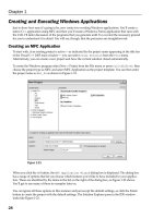
as shown in Figure 13-8.
692
Chapter 13
16_571974 ch13.qxp 1/20/06 11:26 PM Page 692
Figure 13-8
I’ve already entered the information in the dialog box for the
m_Element variable that stores the current
element type to be drawn. I have selected
protected as the access because it should not be accessible
directly from outside the class. I have also selected the type as
unsigned int because you use a posi-
tive integer to identify each type of element. When you click the
Finish button, the variable is added to
the class definition in the
CSketcherDoc.h file.
Add the
CSketcherDoc class member to store the element color manually just to show that you can. Its
name is
m_Color and its type is COLORREF, which is a type defined by the Windows API for represent-
ing a color as a 32-bit integer. You can add the declaration for the
m_Color member to the CSketcherDoc
class like this:
class CSketcherDoc : public CDocument
{
// Generated message map functions
protected:
DECLARE_MESSAGE_MAP()
public:
afx_msg void OnColorBlack();
afx_msg void OnColorRed();
afx_msg void OnColorGreen();
afx_msg void OnColorBlue();
afx_msg void OnElementLine();
afx_msg void OnElementRectangle();
afx_msg void OnElementCircle();
afx_msg void OnElementCurve();
protected:
693
Working with Menus and Toolbars
16_571974 ch13.qxp 1/20/06 11:26 PM Page 693
// Current element type
unsigned int m_Element;
COLORREF m_Color; // Current drawing color
};
The m_Color member is also protected, as there’s no reason to allow public access. You can always add
functions to access or change the values of protected or private class members with the advantage that
you then have complete control over what values can be set.
Initializing the New Class Data Members
You need to decide how to represent an element type. You could just set m_Element to a unique numeric
value, but this would introduce “magic numbers” into the program, the significance of which would be
less than obvious to anyone else looking at the code. A better way would be to define a set of constants
that you can use to set values for the member variable,
m_Element. In this way, you can use a standard
mnemonic to refer to a given type of element. You could define the element types with the following
statements:
// Element type definitions
// Each type value must be unique
const unsigned int LINE = 101U;
const unsigned int RECTANGLE = 102U;
const unsigned int CIRCLE = 103U;
const unsigned int CURVE = 104U;
The constants initializing the element types are arbitrary unsigned integers. You can choose different
values, if you like, as long as they are all distinct. If you want to add further types in the future, it will
obviously be very easy to add definitions here.
For the color values, it would be a good idea if we used constant variables that are initialized with the val-
ues that Windows uses to define the color in question. You could do this with the following lines of code:
// Color values for drawing
const COLORREF BLACK = RGB(0,0,0);
const COLORREF RED = RGB(255,0,0);
const COLORREF GREEN = RGB(0,255,0);
const COLORREF BLUE = RGB(0,0,255);
Each constant is initialized by RGB(), which is a standard macro defined in the Wingdi.h, header file
that is included as part of
Windows.h. The three arguments to the macro define the red, green, and blue
components of the color value respectively. Each argument must be an integer between 0 and 255, where
these limits correspond to no color component and the maximum color component.
RGB(0,0,0) corre-
sponds to black because there are no components of red, green, or blue.
RGB(255,0,0) creates a color
value with a maximum red component, and no green or blue contribution. You can create other colors by
combining red, green, and blue components.
You need somewhere to put these constants, so let’s create a new header file and call it
OurConstants.h.
You can create a new file by right-clicking the Header Files folder in the Solution Explorer tab and select-
ing the
Add > Add New Item menu option from the pop-up. Enter the header file name OurConstants
in the dialog box that displays and then click the Open button. You’ll then be able to enter the constant
definitions in the Editor window as shown here.
694
Chapter 13
16_571974 ch13.qxp 1/20/06 11:26 PM Page 694
//Definitions of constants
#pragma once
// Element type definitions
// Each type value must be unique
const unsigned int LINE = 101U;
const unsigned int RECTANGLE = 102U;
const unsigned int CIRCLE = 103U;
const unsigned int CURVE = 104U;
///////////////////////////////////
// Color values for drawing
const COLORREF BLACK = RGB(0,0,0);
const COLORREF RED = RGB(255,0,0);
const COLORREF GREEN = RGB(0,255,0);
const COLORREF BLUE = RGB(0,0,255);
///////////////////////////////////
As you’ll recall, the pre-processor directive #pragma once is there to ensure that the definitions cannot
be included more than once in a file. The statements in the header file are included into a source file only
by an
#include directive if it has hasn’t been included previously. After the header has been included in
a file, the statements will not be included again.
After saving the header file, you can add the following
#include statement to the beginning of the file
Sketcher.h:
#include “OurConstants.h”
Any .cpp file that has an #include directive for Sketcher.h has the constants available.
You can verify that the new constants are now part of the project by expanding
Global Functions
and Variables
in the Class View. You’ll see the names of the color and element types that have been
added now appear along with the global variable
theApp.
Modifying the Class Constructor
It’s important to make sure that the data members you have added to the CSketcherDoc class are ini-
tialized appropriately when a document is created. You can add the code to do this to the class construc-
tor as shown here:
CSketcherDoc::CSketcherDoc() : m_Element(LINE), m_Color(BLACK)
{
// TODO: add one-time construction code here
}
The wizard already has arranged that the m_Element member will be initialized to 0 so change the ini-
tial value to
LINE. You then need to add the initializer for the m_Color member with BLACK as the value
so that everything is consistent with the initial check marks that you specified for the menus.
Now you’re ready to add the code for the handler functions that you created for the
Element and
Color menu items. You can do this from the Class View. Click the name of the first handler function,
OnColorBlack(). You just need to add one line to the function, so the code for it becomes:
695
Working with Menus and Toolbars
16_571974 ch13.qxp 1/20/06 11:26 PM Page 695
void CSketcherDoc::OnColorBlack()
{
m_Color = BLACK; // Set the drawing color to black
}
The only job that the handler has to do is to set the appropriate color. In the interests of conciseness, the
new line replaces the comment provided originally. You can go through and add one line to each of the
Color menu handlers setting the appropriate color value.
The element menu handlers are much the same. The handler for the
Element > Line menu item is:
void CSketcherDoc::OnElementLine()
{
m_Element = LINE; // Set element type as a line
}
With this model, it’s not too difficult to write the other handlers for the Element menu. That’s eight mes-
sage handlers completed. You can now rebuild the example and see how it works.
Running the Extended Example
Assuming that there are no typos, the compiled and linked program should run without error. When
you run the program, you should see the window shown in Figure 13-9.
Figure 13-9
The new menus are in place on the menu bar, and you can see that the items you have added to the
menu are all there, and you should see the
Prompt message in the status bar that you provided in the
properties box when the mouse cursor is over a menu item. You could also verify that
Alt+C and Alt+l
work as well. The things that don’t work are the check marks for the currently selected color and element,
which remain firmly stuck to their initial defaults. Let’s look at how you can fix that.
696
Chapter 13
16_571974 ch13.qxp 1/20/06 11:26 PM Page 696
Adding Message Handlers to Update the User Interface
To set the check mark correctly for the new menus, you need to add the second kind of message handler,
UPDATE_COMMAND_UI (signifying update command user interface), for each of the new menu items.
This sort of message handler is specifically aimed at updating the menu item properties before the item
is displayed.
Go back to viewing the
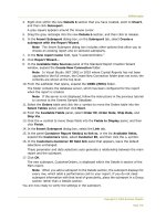
Sketcher.rc file in the Editor window. Right-click the Black item in the Color
menu and select Add Event Handler from the pop-up menu. You can then select UPDATE_COMMAND_UI
as the message type and CSketcherDoc as the class as shown in Figure 13-10.
Figure 13-10
The name for an update function has been generated[md]
OnUpdateColorBlack(). Because this seems
a reasonable name for the function you want, click the Add and Edit button and have the Event Handler
wizard generate it. As well as generating the skeleton function definition in
SketcherDoc.cpp, its declara-
tion is added to the class definition. An entry for it is also made in the message map that looks like this:
ON_UPDATE_COMMAND_UI(ID_COLOR_BLACK, OnUpdateColorBlack)
This uses the ON_UPDATE_COMMAND_UI() macro that identifies the function you have just generated as
the handler to deal with update messages corresponding to the ID shown. You could now enter the code
for the new handler but I’ll let you add command update handlers for each of the menu items for both
the
Color and Element menus first.
Coding a Command Update Handler
You can access the code for the OnUpdateColorBlack() handler in the CSketcherDoc class by select-
ing the function in Class View. This is the skeleton code for the function:
697
Working with Menus and Toolbars
16_571974 ch13.qxp 1/20/06 11:26 PM Page 697
void CSketcherDoc::OnUpdateColorBlack(CCmdUI* pCmdUI)
{
// TODO: Add your command update UI handler code here
}
The argument passed to the handler is a pointer to an object of the CCmdUI class type. This is an MFC
class that is only used with update handlers, but it applies to toolbar buttons as well as menu items. The
pointer points to an object that identifies the item that originated the update message so you use this to
operate on the item to update how it appears before it is displayed. The
CCmdUI class has five member
functions that act on user interface items. The operations that each of these provides is as follows:
Method Description
ContinueRouting() Passes the message on to the next priority handler.
Enable() Enables or disables the relevant interface item.
SetCheck() Sets a check mark for the relevant interface item.
SetRadio() Sets a button in a radio group on or off.
SetText() Sets the text for the relevant interface item.
We’ll use the third function,
SetCheck(), as that seems to do what we want. The function is declared in
the
CCmdUI class as:
virtual void SetCheck(int nCheck = 1);
This function sets a menu item as checked if you pass 1 as the argument and set it unchecked if you pass
0 as the argument. The parameter has a default value of 1, so if you just want to set a check mark for a
menu item regardless, you can call this function without specifying an argument.
In our case, you want to set a menu item as checked if it corresponds with the current color. You can,
therefore, write the update handler for
OnUpdateColorBlack() as:
void CSketcherDoc::OnUpdateColorBlack(CCmdUI* pCmdUI)
{
// Set menu item Checked if the current color is black
pCmdUI->SetCheck(m_Color==BLACK);
}
The statement you have added calls the SetCheck() function for the Color > Black menu item, and
the argument expression
m_Color==BLACK results in 1 if m_Color is BLACK, or 0 otherwise. The effect,
therefore, is to check the menu item only if the current color stored in
m_Color is BLACK, which is pre-
cisely what you want.
The update handlers for all the menu items in a menu are always called before the menu is displayed so
you can code the other handlers in the same way to ensure that only the item corresponding to the cur-
rent color (or the current element) is checked:
698
Chapter 13
16_571974 ch13.qxp 1/20/06 11:26 PM Page 698
void CSketcherDoc::OnUpdateColorBlue(CCmdUI* pCmdUI)
{
// Set menu item Checked if the current color is blue
pCmdUI->SetCheck(m_Color==BLUE);
}
void CSketcherDoc::OnUpdateColorGreen(CCmdUI* pCmdUI)
{
// Set menu item Checked if the current color is green
pCmdUI->SetCheck(m_Color==GREEN);
}
void CSketcherDoc::OnUpdateColorRed(CCmdUI* pCmdUI)
{
// Set menu item Checked if the current color is red
pCmdUI->SetCheck(m_Color==RED);
}
A typical Element menu item update handler is coded as:
void CSketcherDoc::OnUpdateElementLine(CCmdUI* pCmdUI)
{
// Set Checked if the current element is a circle
pCmdUI->SetCheck(m_Element==LINE);
}
You can now code all the other update handlers in a similar manner:
void CSketcherDoc::OnUpdateElementCurve(CCmdUI* pCmdUI)
{
// Set Checked if the current element is a curve
pCmdUI->SetCheck(m_Element==CURVE);
}
void CSketcherDoc::OnUpdateElementCircle(CCmdUI *pCmdUI)
{
// Set Checked if the current element is a circle
pCmdUI->SetCheck(m_Element==CIRCLE);
}
void CSketcherDoc::OnUpdateElementRectangle(CCmdUI* pCmdUI)
{
// Set Checked if the current element is a rectangle
pCmdUI->SetCheck(m_Element==RECTANGLE);
}
After you get the idea, it’s easy, isn’t it?
Exercising the Update Handlers
When you’ve added the code for all the update handlers, you can build and execute the Sketcher appli-
cation again. Now, when you change a color or an element type selection, this is reflected in the menu,
as shown in Figure 13-11.
699
Working with Menus and Toolbars
16_571974 ch13.qxp 1/20/06 11:26 PM Page 699
Figure 13-11
You have completed all the code that you need for the menu items. Make sure that you have saved
everything before embarking on the next stage. These days, toolbars are a must in any Windows pro-
gram of consequence, so the next step is to take a look at how you can add toolbar buttons to support
our new menus.
Adding Toolbar Buttons
Select the Resource View and extend the toolbar resource. You’ll see that it has the same ID as the main
menu,
IDR_MAINFRAME. If you double-click this ID, the Editor window appears as shown in Figure 13-12.
Figure 13-12
700
Chapter 13
16_571974 ch13.qxp 1/20/06 11:26 PM Page 700
A toolbar button is a 16x15 array of pixels that contains a pictorial representation of the function it oper-
ates. You can see in Figure 13-12 that the resource editor provides an enlarged view of a toolbar button
so that you can see and manipulate individual pixels. If you click the new button at the right end of the
row as indicated, you’ll be able to draw this button. Before starting the editing, drag the new button
about half a button width to the right. It separates from its neighbor on the left to start a new block.
You should keep the toolbar button blocks in the same sequence as the items on the menu bar, so you’ll
create the element type selection buttons first. You’ll be using the following editing buttons provided by
the resource editor that appear in the toolbar for the Visual C++ 2005 application window.
❑ Pencil for drawing individual pixels
❑ Eraser for erasing individual pixels
❑ Fill an area with the current color
❑ Zoom the view of the button
❑ Draw a rectangle
❑ Draw an ellipse
❑ Draw a curve
If it is not already visible, you can display the window for selecting a color by right-clicking a toolbar
button and selecting Show Colors Window from the pop-up. Make sure that the black color is selected
and use the pencil tool to draw a diagonal line in the enlarged image of the new toolbar button. In fact, if
you want it a bit bigger, you can use the Magnification Tool editing button to enlarge it up to eight times
its actual size. If you make a mistake, you can change to the Erase Tool editing button, but you need to
make sure that the color selected corresponds to the background color for the button you are editing.
You can also erase individual pixels by clicking them using the right mouse button, but again you need
to be sure that the background color is set correctly when you do this. To set the background color, just
click the appropriate color using the right mouse button. After you’re happy with what you’ve drawn,
the next step is to edit the toolbar button properties.
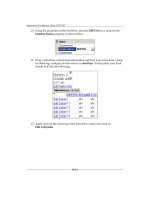
Editing Toolbar Button Properties
Double-click your new button in the toolbar to bring up its properties window, as shown in Figure 13-13.
The properties box shows a default ID for the button, but you want to associate the button with the
menu item
Element > Line that we’ve already defined, so click ID and then click the down arrow to
display alternative values. You can then select
ID_ELEMENT_LINE from the drop-down box. If you click
on
Prompt you’ll find that this also causes the same prompt to appear in the status bar because the
prompt is recorded along with the ID. You can close the
Properties window to complete the button
definition.
You can now move on to designing the other three element buttons. You can use the rectangle editing
button to draw a rectangle and the ellipse button to draw a circle. You can draw a curve using the pencil
to set individual pixels, or use the curve button. You need to associate each button with the ID corre-
sponding to the equivalent menu item that you defined earlier.
701
Working with Menus and Toolbars
16_571974 ch13.qxp 1/20/06 11:26 PM Page 701
Figure 13-13
Now add the buttons for the colors. You should also drag the first button for selecting a color to the right
so that it starts a new group of buttons. You could keep the color buttons very simple and just color the
whole button with the color it selects. You can do this by selecting the appropriate foreground color, then
selecting the “fill” editing button and clicking on the enlarged button image. Again you need to use
ID_COLOR_BLACK, ID_COLOR_RED, and so on, as IDs for the buttons. The toolbar editing window should
look like the one shown in Figure 13-14.
Figure 13-14
That’s all you need for the moment, so save the resource file and give Sketcher another spin.
702
Chapter 13
16_571974 ch13.qxp 1/20/06 11:26 PM Page 702
Exercising the Toolbar Buttons
Build the application once again and execute it. You should see the application window shown in
Figure 13-15.
Figure 13-15
There are some amazing things happening here. The toolbar buttons that you added already reflect the
default settings that you defined for the new menu items. If you let the cursor linger over one of the new
buttons, the prompt for the button appears in the status bar. The new buttons work as a complete substi-
tute for the menu items and any new selection made, using either the menu or the toolbar, is reflected by
showing the toolbar button depressed, as well as the check against the menu item.
If you close the document view window, Sketcher1, you’ll see that our toolbar buttons are automatically
grayed and disabled. If you open a new document window, they are automatically enabled once again.
You can also try dragging the toolbar with the cursor. You can move it to either side of the application
window, or have it free-floating. You can also enable or disable it through the
View > Toolbar menu
option. You got all this without writing a single additional line of code!
Adding Tooltips
There’s one further tweak that you can add to your toolbar buttons that is remarkably easy: adding
tooltips. A tooltip is a small box that appears adjacent to the toolbar button when you let the cursor
linger on the button. The tooltip contains a text string that is an additional clue as to the purpose of the
toolbar button.
To add tooltips, select the Resource View tab and, after expanding the resource list, click the String Table
folder and double-click the resource. This contains the IDs and prompt strings associated with menu items
and toolbar buttons. You should see the IDs for the menus that you added earlier together with the prompt
text for each under the caption heading. To add a tooltip, you just need to add
\n (the newline character),
followed by the tooltip text to the end of the caption text. For the prompt text you have already entered you
can double-click text to enable editing of it and then add
\n to the end of the prompt text in the caption
703
Working with Menus and Toolbars
16_571974 ch13.qxp 1/20/06 11:26 PM Page 703
column, so you could change the existing caption for the ID_ELEMENT_LINE ID from Line to Line\
nSets line drawing mode
, for example. Thus the caption text has two parts separated by \n, the first
part being the prompt that appears in the status bar and the second is the tooltip text.
Add
\n followed by a tooltip to the caption text for each of the IDs for the menu items in the Element
and Color menus —not forgetting to start each tooltip text with \n. That’s all you have to do. After sav-
ing the
String Table resource, you can now rebuild the application and execute it. Placing the cursor
over one of the new toolbar buttons causes the tooltip to be displayed after a second or two.
Summary
In this chapter, you learned how MFC connects a message with a class member function to process it,
and you wrote your first message handlers. Much of the work in writing a Windows program is writing
message handlers, so it’s important to have a good grasp of what happens in the process. When we get
to consider other message handlers, you’ll see that the process for adding them is just the same.
You have also extended the standard menu and the toolbar in the MFC Application wizard-generated
program, which provides a good base for the application code that we add in the next chapter. Although
there’s no functionality under the covers yet, the menu and toolbar operation looks very professional,
courtesy of the Appwizard-generated framework and the Event Handler wizard.
The important points that you’ve seen in this chapter are:
❑ MFC defines the message handlers for a class in a message map that appears in the
.cpp file for
the class.
❑ Command messages that arise from menus and toolbars can be handled in any class that’s
derived from
CCmdTarget. These include the application class, the frame and child frame win-
dow classes, the document class, and the view class.
❑ Messages other than command messages can only be handled in a class derived from
CWnd. This
includes frame window and view classes, but not application or document classes.
❑ MFC has a predefined sequence for searching the classes in your program to find a message
handler for a command message.
❑ You should always use the Event Handler wizard to add message handlers to your program.
❑ The physical appearances of menus and toolbars are defined in resource files, which are edited
by the built-in resource editor.
❑ Items in a menu that can result in command messages are identified by a symbolic constant with
the prefix
ID. These IDs are used to associate a handler with the message from the menu item.
❑ To associate a toolbar button with a particular menu item, you give it the same ID as that of the
menu item.
❑ To add a tooltip for a toolbar button corresponding to a menu item, you add the tooltip text to
the entry for the ID for the menu item in the caption column in the String Table resource. The
tooltip text is separated from the menu prompt text by \n.
704
Chapter 13
16_571974 ch13.qxp 1/20/06 11:26 PM Page 704
In the next chapter, you’ll add the code necessary to draw elements in a view, and use the menus and
toolbar buttons that you created here to select what to draw and in which color. This is where the Sketcher
program begins to live up to its name.
Exercises
You can download the source code for the examples in the book and the solutions to the following exer-
cises from
.
1. Add a menu item Ellipse to the Element pop-up.
2. Implement the command and command update handlers for it in the document class.
3. Add a toolbar button corresponding to the Ellipse menu item and add a tooltip for the button.
4. Modify the command update handlers for the color menu items so that the currently selected
item is displayed in uppercase, and the others are displayed in lowercase.
705
Working with Menus and Toolbars
16_571974 ch13.qxp 1/20/06 11:26 PM Page 705
16_571974 ch13.qxp 1/20/06 11:26 PM Page 706
14
Drawing in a Window
In this chapter, you will add some meat to the Sketcher application. You’ll focus on understanding
how you get graphical output displayed in the application window. By the end of this chapter,
you’ll be able to draw all but one of the elements for which you have added menu items. I’ll leave
the problem of how to store them in a document until the next chapter. In this chapter, you will
learn about:
❑ What coordinate systems Windows provides for drawing in a window
❑ Device context and why it is necessary
❑ How and when your program draws in a window
❑ How to define handlers for mouse messages
❑ How to define your own shape classes
❑ How to program the mouse to draw your shapes in a window
❑ How to get your program to capture the mouse
Basics of Drawing in a Window
Before I go into drawing using MFC, it will be useful to get a better idea of what is happening under
the covers of the Windows operating system when you are drawing in a window. Similar to any
other operation under Windows, writing to a window on your display screen is achieved through
using Windows API functions. There’s slightly more to it than that though; the way Windows
works complicates the situation somewhat.
For a start, you can’t just write to a window and forget it. There are many events that require that
your application to redraw the window— such as if the user resizes the window that you’re draw-
ing in, for instance or if part of your window that was previously hidden is exposed by the user
moving another window.
17_571974 ch14.qxp 1/20/06 11:22 PM Page 707
Fortunately, you don’t need to worry about the details of such occurrences, because Windows actually
manages all these events for you; however, it does mean that you can only write permanent data to a win-
dow when your application receives a specific Windows message requesting that you do so. It also means
that you need to be able to reconstruct everything that you’ve drawn in the window at any time.
When all, or part, of a window needs to be redrawn, Windows sends a
WM_PAINT message to your appli-
cation. This is intercepted by MFC that passes the message to a function member of one of your classes.
I’ll explain how you handle this a little later in this chapter.
The Window Client Area
A window doesn’t have a fixed position onscreen, or even a fixed visible area, because a window can be
dragged around using the mouse and resized by dragging its borders. How, then, do you know where to
draw onscreen?
Fortunately, you don’t. Because Windows provides you with a consistent way of drawing in a window,
you don’t have to worry about where it is onscreen; otherwise, drawing in a window would be inordi-
nately complicated. Windows does this by maintaining a coordinate system for the client area of a win-
dow that is local to the window. It always uses the upper-left corner of the client area as its reference
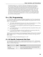
point. All points within the client area are defined relative to this point, as shown in Figure 14-1.
Figure 14-1
The horizontal and vertical distances of a point from the upper-left corner of the client area will always
be the same, regardless of where the window is onscreen or how big it is. Of course, Windows needs to
keep track of where the window is, and when you draw something at a point in the client area, it needs
to figure out where that actually is onscreen.
This is the reference point for this window’s client areas.
x
y
This location of point is defined by the distances x and y.
708
Chapter 14
17_571974 ch14.qxp 1/20/06 11:22 PM Page 708
The Windows Graphical Device Interface
The final constraint Windows imposes is that you don’t actually write data to the screen in any direct
sense. All output to your display screen is graphical, regardless of whether it is lines and circles, or text.
Windows insists that you define this output using the Graphical Device Interface (GDI). The GDI enables
you to program graphical output independently of the hardware on which it is displayed, meaning that
your program works on different machines with different display hardware. In addition to display screens,
the Windows GDI also supports printers and plotters, so outputting data to a printer or a plotter involves
essentially the same mechanisms as displaying information onscreen.
What Is a Device Context?
When you want to draw something on a graphical output device such as the display screen, you must use
a device context. A device context is a data structure that’s defined by Windows and contains information
that allows Windows to translate your output requests, which are in the form of device-independent GDI
function calls, into actions on the particular physical output device being used. A pointer to a device con-
text is obtained by calling a Windows API function.
A device context provides you with a choice of coordinate systems called mapping modes, which is
automatically converted to client coordinates. You can also alter many of the parameters that affect the
output to a device context by calling GDI functions; such parameters are called attributes. Examples of
attributes that you can change are the drawing color, the background color, the line thickness to be used
when drawing and the font for text output. There are also GDI functions that provide information about
the physical device with which you’re working. For example, you may need to be certain that the dis-
play on the computer executing your program can support 256 colors, or that a printer can support the
output of bitmaps.
Mapping Modes
Each mapping mode in a device context is identified by an ID, in a manner similar to what we saw with
Windows messages. Each symbol has the prefix MM_ to indicate that it defines a mapping mode. The
mapping modes provided by Windows are:
Mapping Mode Description
MM_TEXT A logical unit is one device pixel with positive x from left to right, and
positive y from top to bottom of the window client area.
MM_LOENGLISH A logical unit is 0.01 inches with positive x from left to right, and posi-
tive y from the top of the client area upwards.
MM_HIENGLISH A logical unit is 0.001 inches with the x and y directions as in
MM_LOENGLISH.
MM_LOMETRIC A logical unit is 0.1 millimeters with the x and y directions as in
MM_LOENGLISH.
MM_HIMETRIC A logical unit is 0.01 millimeters with the x and y directions as in
MM_LOENGLISH.
MM_ISOTROPIC A logical unit is of arbitrary length, but the same along both the x and y
axes. The x and y directions are as in MM_LOENGLISH.
Table continued on following page
709
Drawing in a Window
17_571974 ch14.qxp 1/20/06 11:22 PM Page 709
Mapping Mode Description
MM_ANISOTROPIC This mode is similar to MM_ISOTROPIC, but allows the length of a logical
unit on the x axis to be different from that of a logical unit on the y axis.
MM_TWIPS A logical unit is a TWIP where a TWIP is 0.05 of a point and a point is
1
⁄72
of an inch. Thus a TWIP corresponds to
1
⁄1440 of an inch, which is 6.9x10
–4
of an inch. (A point is a unit of measurement for fonts.) The x and y
directions are as in MM_LOENGLISH.
You’re not going to be using all of these mapping modes with this book; however, the ones you will use
form a good cross-section of those available, so you won’t have any problem using the others when you
need to.
MM_TEXT is the default mapping mode for a device context. If you need to use a different mapping
mode, you have to take steps to change it. Note that the direction of the positive y axis in the MM_TEXT
mode is opposite to what you saw in high school coordinate geometry, as shown in Figure 14-2.
Figure 14-2
By default, the point at the upper-left corner of the client area has the coordinates (0,0) in every mapping
mode, although it’s possible to move the origin away from the upper-left corner of the client area if you
want to. For example, some applications that present data in graphical form move the origin to the cen-
ter of the client area to make plotting of the data easier. With the origin at the upper-left corner in
MM_TEXT
mode, a point 50 pixels from the left border and 100 pixels down from the top of the client area will have
the coordinates (50,100). Of course, because the units are pixels, the point will be nearer the upper-left
corner of the client area if your monitor is set to use a resolution of 1280x1024 than if it’s working with
the resolution set as 1024x768. An object drawn in this mapping mode will be smaller at the 1280x1024
resolution than it would be at the 1024x768 resolution. Note that the DPI setting for your display affects
presentation in all mapping modes. The default settings assume 96 DPI, so if the DPI for your display is
set to a different value, this affects how thing look. Coordinates are always 32-bit signed integers unless
you are programming for the old Windows95/98 operating systems, in which case they are limited to
16 bits. The maximum physical size of the total drawing varies with the physical length of a coordinate
unit, which is determined by the mapping mode.
Positive y
direction
Positive x
direction
MM_TEXT mapping mode
710
Chapter 14
17_571974 ch14.qxp 1/20/06 11:22 PM Page 710
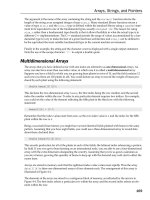
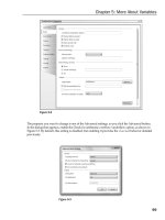
The directions of the x and y coordinate axes in MM_LOENGLISH and all the remaining mapping modes
are the same as each other, but different from
MM_TEXT. The coordinate axes for MM_LOENGLISH are
shown in Figure 14-3. Although positive y is consistent with what you learned in high school (y values
increase as you move up the screen),
MM_LOENGLISH is still slightly odd because the origin is at the
upper-left corner of the client area, so for points within the visible client area, y is always negative.
Figure 14-3
In the
MM_LOENGLISH mapping mode, the units along the axes are 0.01 inches apiece, so a point at the posi-
tion (50, -100) is half an inch from the left border and one inch down from the top of the client area. An
object is the same size in the client area, regardless of the resolution of the monitor on which it is displayed.
If you draw anything in the
MM_LOENGLISH mode with negative x or positive y coordinates, it is outside the
client area and therefore not visible because the reference point (0,0) is the upper-left corner by default.
It’s possible to move the position of the reference point though, by calling the Windows API function
SetViewportOrg() (or the SetViewportOrg() member of the CDC MFC class that I’ll discuss shortly).
The Drawing Mechanism in Visual C++
MFC encapsulates the Windows interface to your screen and printer and relieves you of the need to worry
about much of the detail involved in programming graphical output. As you saw in the last chapter, the
Application wizard-generated program already contains a class derived from the MFC class
CView that’s
specifically designed to display document data onscreen.
The View Class in Your Application
The MFC Application wizard generated the class CSketcherView to display information from a docu-
ment in the client area of a document window. The class definition includes overrides for several virtual
functions, but the one of particular interest in here is the function
OnDraw(). This is called whenever the
client area of the document window needs to be redrawn. It’s the function that’s called by the applica-
tion framework when a
WM_PAINT message is received in your program.
The OnDraw() Member Function
The implementation of the OnDraw() member function that’s created by the MFC Application wizard
looks like this:
Negative y
direction
Positive x
direction
MM_LOENGLISH mapping mode
711
Drawing in a Window
17_571974 ch14.qxp 1/20/06 11:22 PM Page 711
void CSketcherView::OnDraw(CDC* /*pDC*/)
{
CSketcherDoc* pDoc = GetDocument();
ASSERT_VALID(pDoc);
if(!pDoc)
return;
// TODO: add draw code for native data here
}
A pointer to an object of the CDC class type is passed to the OnDraw() member of the view class. This
object has member functions that call the Windows API functions and these allow you to draw in a
device context. Note that the parameter name is commented out so you must uncomment the name or
replace it with your own name before you can use the pointer.
Because you’ll put all the code to draw the document in this function, the Application wizard has
included a declaration for the pointer
pDoc and initialized it using the function GetDocument(), which
returns the address of the document object related to the current view:
CSketcherDoc* pDoc = GetDocument();
The GetDocument() function actually retrieves the pointer to the document from m_pDocument, an inher-
ited data member of the view object. The function performs the important task of casting the pointer stored
in this data member to the type corresponding to the document class in the application,
CSketcherDoc.
This is so that the compiler has access to the members of the document class that you’ve defined; other-
wise, the compiler is able to access only the members of the base class. Thus,
pDoc points to the document
object in your application associated with the current view, and you will be using it to access the data that
you’ve stored in the document object when you want to draw it.
The following line:
ASSERT_VALID(pDoc);
just makes sure that the pointer pDoc contains a valid address and the if statement that follows
ensures that
pDoc is not null.
The name of the parameter
pDC for the OnDraw() function stands for “pointer to Device Context.” The
object of the
CDC class pointed to by the pDC argument that’s passed to the OnDraw() function is the key
to drawing in a window. It provides a device context, plus the tools you need to write graphics and text
to it, so you clearly need to look at it in more detail.
The CDC Class
You should do all the drawing in your program using members of the CDC class. All objects of this class
and classes derived from it contain a device context and the member functions you need for sending
graphics and text to your display and your printer. There are also member functions for retrieving infor-
mation about the physical output device that you are using.
Because
CDC class objects can provide almost everything you’re likely to need by way of graphical out-
put, there are a lot of member functions of this class —in fact, well over a hundred. Therefore, you’ll
712
Chapter 14
17_571974 ch14.qxp 1/20/06 11:22 PM Page 712
only look at the ones you’re going to use in the Sketcher program here in this chapter and go into others
as you need them later on.
Note that MFC includes some more specialized classes for graphics output that are derived from
CDC.
For example, you be using objects of
CClientDC because it is derived from CDC and contains all the mem-
bers we will discuss at this point. The advantage that
CClientDC has over CDC is that it always contains
a device context that represents only the client area of a window, and this is precisely what you want in
most circumstances.
Displaying Graphics
In a device context, you draw entities such as lines, circles, and text relative to a current position. A cur-
rent position is a point in the client area that was set either by the previous entity that was drawn, or by
calling a function to set it. For example, you could extend the
OnDraw() function to set the current posi-
tion as follows:
void CSketcherView::OnDraw(CDC* pDC)
{
CSketcherDoc* pDoc = GetDocument();
ASSERT_VALID(pDoc);
if(!pDoc)
return;
pDC->MoveTo(50, 50); // Set the current position as 50,50
}
The shaded line calls the MoveTo() function for the CDC object pointed to by pDC. This member function
simply sets the current position to the x and y coordinates you specify as arguments. As you saw earlier,
the default mapping mode is
MM_TEXT, so the coordinates are in pixels and the current position will be
set to a point 50 pixels from the inside left border of the window, and 50 pixels down from the top of the
client area.
The
CDC class overloads the MoveTo() function to provide flexibility over how you specify the position
that you want to set as the current position. There are two versions of the function, declared in the
CDC
class as:
CPoint MoveTo(int x, int y); // Move to position x,y
CPoint MoveTo(POINT aPoint); // Move to position defined by aPoint
The first version accepts the x and y coordinates as separate arguments. The second accepts one argu-
ment of type
POINT, which is a structure defined as:
typedef struct tagPOINT
{
LONG x;
LONG y;
} POINT;
The coordinates are members of the struct and are of type LONG (which is type defined in the Windows
API corresponding to a 32-bit signed integer). You may prefer to use a class instead of a structure, in
which case you can use objects of the class
CPoint anywhere that a POINT object can be used. The class
CPoint has data members x and y of type LONG, and using CPoint objects has the advantage that the
713
Drawing in a Window
17_571974 ch14.qxp 1/20/06 11:22 PM Page 713
class also defines member functions that operate on CPoint and POINT objects. This may seem weird
because
CPoint would seem to make POINT objects obsolete, but remember that the Windows API was
built before MFC was around, and
POINT objects are used in the Windows API and have to be dealt with
sooner or later.
CPoint objects are used in examples, so you’ll have an opportunity to see some of the
member functions in action.
The return value from the
MoveTo() function is a CPoint object that specifies the current position as it
was before the move. You might think this a little odd, but consider the situation where you want to move
to a new position, draw something, and then move back. You may not know the current position before
the move, and after the move occurs, it would be lost so returning the position before the move makes
sure it’s available to you if you need it.
Drawing Lines
You can follow the call to MoveTo() in the OnDraw() function with a call to the function LineTo(),
which draws a line in the client area from the current position to the point specified by the arguments to
the
LineTo() function, as illustrated in Figure 14-4.
Figure 14-4
The
CDC class also defines two versions of the LineTo() function that have the following prototypes:
BOOL LineTo(int x, int y); // Draw a line to position x,y
BOOL LineTo(POINT aPoint); // Draw a line to position defined by aPoint
This offers you the same flexibility in specifying the argument to the function as MoveTo(). You can use
a
CPoint object as an argument to the second version of the function. The function returns TRUE if the
line was drawn and
FALSE otherwise.
When the
LineTo() function is executed, the current position is changed to the point specifying the end
of the line. This allows you to draw a series of connected lines by just calling the
LineTo() function for
each line. Look at the following version of the
OnDraw() function:
Set the current position to here
Y-Axis
X-Axis
50,50
150,100
Units are pixels.
Draw a line to here
pDC->MoveTo(50,50);
pDC->MoveTo(150,100);
714
Chapter 14
17_571974 ch14.qxp 1/20/06 11:22 PM Page 714
void CSketcherView::OnDraw(CDC* pDC)
{
CSketcherDoc* pDoc = GetDocument();
ASSERT_VALID(pDoc);
if(!pDoc)
return;
pDC->MoveTo(50,50); // Set the current position
pDC->LineTo(50,200); // Draw a vertical line down 150 units
pDC->LineTo(150,200); // Draw a horizontal line right 100 units
pDC->LineTo(150,50); // Draw a vertical line up 150 units
pDC->LineTo(50,50); // Draw a horizontal line left 100 units
}
If you plug this into the Sketcher program and execute it, it displays the document window shown in
Figure 14-5.
Figure 14-5
The four calls to the
LineTo() function draw the rectangle shown counterclockwise, starting with the
upper-left corner. The first call uses the current position set by the
MoveTo() function; the succeeding
calls use the current position set by the previous
LineTo() function call. You can use this to draw any
figure consisting of a sequence of lines, each connected to the previous line. Of course, you are also free
to use
MoveTo() to change the current position at any time.
Drawing Circles
You have a choice of several function members in the CDC class for drawing circles, but they’re all
designed to draw ellipses. As you know from high school geometry, a circle is a special case of an ellipse,
715
Drawing in a Window
17_571974 ch14.qxp 1/20/06 11:22 PM Page 715
with the major and minor axes equal. You can, therefore, use the member function Ellipse() to draw a
circle. Like other closed shapes supported by the
CDC class, the Ellipse() function fills the interior of
the shape with a color that you set. The interior color is determined by a brush that is selected into the
device context. The current brush in the device context determines how any closed shape is filled.
MFC provides the
CBrush class that you can use to define a brush. You can set the color of a CBrush
object and also define a pattern to be produced when filling a closed shape. If you want to draw a closed
shape that isn’t filled, you can use a null brush, which leaves the interior of the shape empty. I’ll come
back to brushes a little later in this chapter.
Another way to draw circles that aren’t filled is to use the
Arc() function, which doesn’t involve brushes.
This has the advantage that you can draw any arc of an ellipse, rather than the complete curve. There are
two versions of this function in the
CDC class, declared as:
BOOL Arc(int x1, int y1, int x2, int y2, int x3, int y3, int x4, int y4);
BOOL Arc(LPCRECT lpRect, POINT StartPt, POINT EndPt);
In the first version, (x1,y1) and (x2,y2) define the upper-left and lower-right corners of a rectangle
enclosing the complete curve. If you make these coordinates into the corners of a square, the curve
drawn is a segment of a circle. The points (
x3,y3) and (x4,y4) define the start and end points of the seg-
ment to be drawn. The segment is drawn counterclockwise. If you make (
x4,y4) identical to (x3,y3),
you’ll generate a complete, apparently closed curve.
In the second version of
Arc(),the enclosing rectangle is defined by a RECT object, and a pointer to this
object is passed as the first argument. The function also accepts a pointer to an object of the class
CRect,
which has four public data members:
left, top, right, and bottom. These correspond to the x and y
coordinates of the upper-left and lower-right points of the rectangle respectively. The class also provides
a range of function members that operate on
CRect objects, and we shall be using some of these later.
The
POINT objects StartPt and EndPt in the second version of Arc() define the start and end of the arc
to be drawn.
Here’s some code that exercises both versions of the
Arc() function:
void CSketcherView::OnDraw(CDC* pDC)
{
CSketcherDoc* pDoc = GetDocument();
ASSERT_VALID(pDoc);
if(!pDoc)
return;
pDC->Arc(50,50,150,150,100,50,150,100); // Draw the 1st (large) circle
// Define the bounding rectangle for the 2nd (smaller) circle
CRect* pRect = new CRect(250,50,300,100);
CPoint Start(275,100); // Arc start point
CPoint End(250,75); // Arc end point
pDC->Arc(pRect,Start, End); // Draw the second circle
delete pRect;
}
716
Chapter 14
17_571974 ch14.qxp 1/20/06 11:22 PM Page 716