PC Upgrade and Repair Bible Desktop Edition phần 5 pptx
Bạn đang xem bản rút gọn của tài liệu. Xem và tải ngay bản đầy đủ của tài liệu tại đây (2.34 MB, 51 trang )
Network Technologies
After you have a medium running from one place to another, you need to put a
network on top of it. There are many different approaches, the most common
of which is Ethernet. Most of the other network technologies have been devel-
oped to address one or another limitation of Ethernet — speed, distance, or
the need for a cable. Table 12-1 summarizes the key characteristics of the most
common local network technologies — Ethernet and wireless.
Table 12-1
Characteristics of Common Network Technologies
Characteristic Ethernet Wireless
Data rate 10 or 100 Mbps 1 to 54 Mbps
Maximum distance 185 m (607 feet) for 10s of feet to miles
between stations 10Base-2; up to 2.8 km for optical fiber
(1.7 miles)
Logical topology Bus Bus
Physical topology Star, bus Point-to-point or star
Media Optical fiber, twisted-pair, Radio
coaxial cable
Access method CSMA/CD TDMA, FDMA, CDMA
In addition to networks having overall characteristics, every network imple-
mentation has a specific medium it uses to transmit signals. Collectively, we’ll
call the network medium its cable (or cable type), ignoring the fact that wire-
less transmissions don’t have a physical cable.
Ethernet
Ethernet was among the earliest networks. The initial version of Ethernet used
a thick coaxial cable about 0.4 inches in diameter. Later copper-based versions
used a thinner coaxial cable, before the evolution to today’s twisted copper
pairs. For example, one of the oldest surviving variants of Ethernet, 10Base-2,
uses flexible coaxial cable to carry the LAN signal, and makes connections with
a twist-lock BNC connector. Limitations on the transmission characteristics of
the 10Base-2 signal and cable cause restrictions on the way you use 10Base-2
to connect computers:
✦ No external transceiver or AUI cable — The 10Base-2 transceiver is
built into the adapter card in your PC. A tee coaxial connector mounts
on the back of the board, and the cable attaches to both sides of the
tee. If one side of the tee has no cable attached, a terminator attaches
directly to the tee. You must not use a segment of cable to space the
tee away from the adapter card.
Chapter 12 ✦ Wired and Wireless Networking 179
✦ No spur directly connected segments — No branches off the 10Base-
2 cable are allowed — even to connect a computer to the associated
tee connector. The cable must run to the tee connector directly on
the adapter card.
✦ Maximum transmission length — The maximum segment length is
185 meters (607 feet). You can attach up to 30 computers to a seg-
ment. There are no special spacing requirements between computers
except that the minimum spacing is 0.5 meters (1.6 feet).
If you open the coaxial cable at any point, the entire network segment goes down.
You can remove a computer from a 10Base-2 segment, but you have to do it by
removing the tee connector from the back of the computer. It’s very common to
use a short spur segment from the tee connector to the back of the computer,
but it’s a very bad idea. The spur causes signal reflections, degrading the signal
on the network and causing errors. The error rate goes up as the load on the
network goes up, and as the number of spurs (and their length) goes up.
If you have a 10Base-2 network, check the connectors, terminators,
and especially the tees often. Cracked parts make your LAN unreliable or
inoperative.
By far the dominant Ethernet cabling technology is twisted-pair — a bundle of
four pairs of wires, each pair twisted together, and the entire set wrapped in an
outside jacket. There are two variants of twisted-pair network wiring, 10Base-T
(which runs at 10 Mbps), and 100Base-T (which runs at 100 Mbps). The two
variants are commonly termed 10/100Base-T when it doesn’t matter which one
you’re talking about.
10/100Base-T attaches only one computer to each wire segment, combining
segments to form the network. Each segment contains two twisted-pairs of
wire: one pair for transmitting and one for receiving. The wires have an RJ-45
modular connector (slightly larger than the usual RJ-11 connector on most
telephones) at each end (Figure 12-1). One end connects to the computer, while
the other connects to a device that joins all the separate segments together
(Figure 12-2). That device is called a hub or a switch, depending on its internal
characteristics. You can get hubs and switches to join from 4 to 24 (or more)
segments together and can join hubs and switches together to create even
larger networks. Ethernet switches increase twisted-pair network performance
by letting many computers transmit at the same time, separating the traffic of
each computer pair from the rest.
Twisted-pair connections can be up to 100 meters (328 feet) long. If you allow
10 meters (total) for connections within a wiring closet and from the wall to the
computer, the in-wall wiring can be up to 90 meters. Both unshielded twisted-
pair (UTP) and shielded twisted-pair (STP) are used, differing in that STP has
shielding wrapped around the conductors to minimize noise and interference.
Therefore, STP has better transmission characteristics than UTP, but twisted-
pair wiring is almost universally done with UTP. Twisted-pair wiring provides
separate wire pairs for transmitting and receiving. Twisted-pair can therefore
operate in full-duplex, which means that it’s possible for a computer to trans-
mit and receive simultaneously.
180 Part V ✦ Networks and Communications
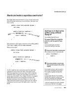
Figure 12-1: RJ-45 connector on Ethernet cable
©2004 Barry Press & Marcia Press
Figure 12-2: Twisted-pair Ethernet (10/100Base-T and
gigabit Ethernet) attaches one computer per cable.
If any one wire goes down, the rest of the computers
are unaffected.
In addition to the division between shielded and unshielded wire, there are cat-
egories of twisted-pair wiring, differentiated by their capability to transport the
network signal without distortions, called Category-3, -5, -5e, and -6. Category-3
is the usual voice-grade wiring that is commonly pre-wired in buildings.
Twisted-pair
segments
Twisted-pair
segments
Wiring
hub
Chapter 12 ✦ Wired and Wireless Networking 181
Categories-5, 5e, and 6 use successively higher-quality cables and connectors.
If you ever plan to upgrade from 10Base-T to 100Base-T, you want to start with
Category-5, 5e, or 6. Your network runs no better than its worst wiring compo-
nent. In other words, use Category-3 connectors with Category-6 wire and you
have a Category-3 network.
Table 12-2 summarizes the twisted-pair wiring categories. You should avoid
Category-3, but any of the other three are suitable for home, home office, and
small networks. If you’re building a large LAN, plan on using Category-5e or
Category-6.
Table 12-2
Twisted-Pair Wiring Specifications
Specification Frequency Rating Application
Category-3 Basic, nonupgradeable twisted-pair
networks
Category-5 100 MHz Basic Fast Ethernet networks without
full-duplex links, or (risky) gigabit
Ethernet networks
Category-5e 100 MHz Fast Ethernet networks running
(Enhanced Category-5) full-duplex Gigabit Ethernet networks
Category-6 250 MHz Gigabit Ethernet networks (solid)
Ethernet cables in the walls typically terminate at RJ-45 jacks, and you use patch
cords to connect from the wall jacks to computers, hubs, switches, or other
devices. Patch cords have RJ-45 plugs at both ends. If you have the tools to
attach the modular connectors, you can make twisted-pair patch cables yourself.
If not, you’ll have to order them in the right length. Either way, if you make a
cable that reverses the transmit and receive pairs between the connectors — a
crossover cable — you can connect two computers directly, without a wiring hub.
Twisted-pair interfaces monitor the link status, and most provide a light to
indicate that the link is up. You have to check the lights at both ends, though,
because link status is based on the receive side only.
Ethernet is designed for shared media. Point-to-point wiring (such as twisted-
pair) connects the wiring segments together electrically in most cases, creating
a shared medium through the wiring hub. Similarly, Ethernet can be either half-
duplex or full-duplex, depending on the physical medium and attached network
devices. Ethernets use carrier sense with collision detection to support multi-
ple access. When any given transmitter has something to send, it listens on
the network to try to verify that no other device is currently transmitting. If the
network appears idle, it starts to send. Because transmitters can be relatively
far apart, however, it’s possible for two transmitters to sense that the network
182 Part V ✦ Networks and Communications
is idle and both start to transmit at roughly the same time. Ethernet trans-
ceivers detect this occurrence and schedule a retransmission. The time for the
retransmission is based on a random number to help the two colliding stations
avoid further contention.
The shared medium amounts to a “cloud” that interconnects all nodes on the
network equally. Addresses in each network message define both the source
and the destination of the message.
Keep in mind that an unencrypted shared medium (such as Ethernet) is
inherently insecure. On any one network segment, every packet arrives at
every transceiver, and a transceiver programmed to listen to all addresses
indiscriminately hears them all. This is useful for building network analyzers,
but it means that, with the right software, the traffic from the executive suite
to marketing is equally visible to anyone else connected to the network.
Another downside of Ethernet has been its limitation to 10 or 100 Mbps on a sin-
gle segment. As fast as that seems, when you start to transfer huge files across
the network (such as raw video recordings) or connect tens or hundreds of
computers to a single segment, network performance accessing the file servers
quickly becomes intolerable. Gigabit Ethernet solves that problem, offering
full-duplex Ethernet operation on your existing unshielded twisted-pair wiring
at 1,000 Mbps.
Table 12-3 shows the variants of Gigabit Ethernet:
Table 12-3
Gigabit Ethernet Variants
Designation Media Distance
1000Base-SX Multimode optical fiber (850 nm) 500 m
1000Base-LX Multimode and single mode optical fiber (1300 nm) 500 m to 2 km
1000Base-CX Short-haul copper (“twinax” shielded twisted-pair) 25 m
1000Base-T Long-haul copper over unshielded twisted-pair 25 to 100 m
The compatibility with existing wiring simplifies deployment, although distance
limitations may be a factor. The first uses of gigabit Ethernet were to connect
servers to networks and to interconnect switches as the network backbone.
High-performance applications such as video editing are driving gigabit Ethernet
out towards individual computers. The need for gigabit Ethernet isn’t specula-
tion. A high-performance server can, today, generate sustained network traffic
in the 300 Mbps and up range, so a highly loaded backbone with several servers
will benefit from the performance boost. You could see performance gains in
the home or small office too — for example, a 10GB video file that takes about
20 minutes to transfer between computers over 100 Mbps Ethernet would take
only a minute and a half over gigabit Ethernet.
Chapter 12 ✦ Wired and Wireless Networking 183
Ethernet adapters are one of the products that we’re picky about. Networks
are difficult enough to set up and keep running reliably; you don’t need extra
excitement on that front. We’ve found adapters from 3Com, Linksys, and NET-
GEAR dependable, as well as adapters built into the Intel motherboards, and
have the scars to prove that less expensive isn’t always better. We’ve thrown
away a network card that was a solid piece of hardware, for example, because
it had an admittedly buggy driver that the vendor never fixed.
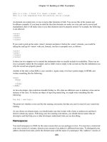
We recommend using motherboards with built-in Ethernet adapters, such as that
on the Intel D875PBZ motherboard (Figure 12-3). Otherwise, 10/100/1000Base-T
adapters — stay with the top manufacturers — are a commodity you can buy
based on price and availability. Either way, market price pressures have driven
the adapters to be integrated into little more than a single chip.
Figure 12-3: 10/100/1000Base-T Ethernet adapter built into the Intel D875PBZ
motherboard
©2004 Barry Press & Marcia Press
Gigabit Ethernet is new enough that it’s particularly important to use adapters
(and other network components) from first-line manufacturers.
Wireless transmission
Wireless networks use radio or light waves to communicate between stations.
The frequencies for radio-based networks vary based on national licensing.
Systems in the United States often use bands designated by the Federal
Communications Commission for “unlicensed” operation, meaning that, after
Ethernet RJ-45 connector
USB 2.0 connectors
184 Part V ✦ Networks and Communications
the manufacturer has qualified the equipment, the operator doesn’t need spe-
cial training or licensing. Optical systems often use infrared frequencies (light
waves just below the visible spectrum). Some of the key characteristics are:
✦ Range — Radio systems have ranges up to tens of miles. Infrared
systems are typically limited to a few hundred feet.
✦ Blockage — Radio waves penetrate walls and floors with varying
degrees of success. Light waves require a direct line of sight between
the transmitter and receiver.
✦ Data rate — Radio systems don’t always carry the usual 10 Mbps
Ethernet rate, particularly at longer ranges. Radio data rates vary
from 1 Mbps to hundreds of megabits per second, with the most
common variants running between 1 and 54 Mbps. Short-range
infrared systems tend to operate at speeds of 10 to 100 Kbps,
although some operate as fast as 4 Mbps.
Wireless networks can operate with point-to-point topologies, like twisted-pair
networks, or with shared access, like coaxial-cable networks.
Optical wireless and many radio wireless networks use a central node, called
a base station, which corresponds to a wiring hub in a 10/100Base-T network.
Transmissions between computers go through the base station and are
retransmitted after reception if the destination is also on the wireless network.
(Base stations are commonly attached to a wired network as well, giving the
mobile units access to the wider network.) Networks organized with a base
station generally transmit out of the base station on one frequency and receive
on another; the computers reverse the frequency assignments. Radio networks
without a base station let all units transmit on the same frequency.
In either scheme, wireless networks require a method for collision detection.
The carrier sense/collision detection approach used in Ethernet doesn’t work
well on wireless networks because of the time delay between the start of the
transmission and when the receiver notices the carrier. The relatively long
latency while the receiver locks up on the signal creates too long a window in
which a second transmitter might start operations and step on the transmis-
sions of the first one. That’s why many wireless networks use an access
scheme that positively identifies the next station allowed to transmit.
Some radio networks use spread spectrum technology to isolate transmissions
from one another. Spread spectrum is an inherently noise resistant transmission.
There are two forms of spread spectrum: frequency hopping and direct sequence.
✦ A frequency hopper divides the overall allocated spectrum into many
small bands, transmitting for only a brief moment in one before hop-
ping to the next. The hops are made in a predetermined sequence.
Frequency hoppers resist interference and jamming by either avoid-
ing the noisy channels or dwelling in them for a very short a time.
✦ The second form of spread spectrum, direct sequence, enables all
the transmitted signals to use the entire allocated band at once. The
greater the ratio of the available channel bandwidth to the data rate,
the more interference and jamming-resistant the signal will be.
Chapter 12 ✦ Wired and Wireless Networking 185
186 Part V ✦ Networks and Communications
The advantages that wireless networks have over wired ones are mobility and
not having to run wires (not as silly as it sounds). In addition to being able to
move around — useful if you’re taking inventory in a warehouse, for example —
a wireless connection can solve the problem of linking networks that have
physical barriers between them. Point-to-point wireless links can solve the
problem of how to cross roads and railways between building networks, or of
how to cross parts of a town without the expense of a leased telephone line.
Multidrop wireless networks can simplify linking stations on several floors of
the same building when it’s impractical to run wires between the networks.
Wireless networks are generally more expensive than their wired equivalents,
so you want to use them only where mobility or access is an issue.
IEEE specification 802.11 standardizes the most common wireless LAN tech-
nologies. There are three variants, IEEE 802.11b, 802.11a, and 802.11g.
✦ IEEE 802.11b — Also known as WiFi (for Wireless Fidelity), IEEE
802.11b networks run at rates from 1 to 11 Mbps over relatively short
ranges. You can run a WiFi network in ad hoc mode, in which two
computers talk directly among themselves, or in infrastructure mode,
in which the computers talk through a central wireless access point
(Figure 12-4). Access points are commonly packaged with routers to
create a device that interfaces both the wireless network and a LAN
together and to an external Internet connection. IEEE 802.11b net-
works operate at 2.4 GHz frequencies, a band shared by wireless tele-
phones, Bluetooth networks, and a variety of other equipment. IEEE
802.11b network installations have grown explosively in recent years,
and the equipment has become quite inexpensive.
Figure 12-4: Wireless LAN modes
Infrastructure modeAd hoc mode
To wired LAN
Chapter 12 ✦ Wired and Wireless Networking 187
Sharing Frequencies with Spread Spectrum
There’s an interesting operation computers do on numbers, called “exclusive or”
or “XOR.” The XOR operation is interesting because if you do it twice, you get
back your original number. For instance, if we compute
11001010 XOR 11111111
we get 00110101. All the bits in the initial number have flipped. If we repeat the
operation on the result and do
00110101 XOR 11111111
we get 11001010 again. Now, suppose we take two digital signals: one a real
data stream and one a much faster stream of random numbers. If we XOR the
two streams together, we pretty much get garbage out, but we can throw away
the garbage and get back the data stream if we repeat the XOR using the exact
same random number sequence.
In a nutshell, that’s what direct sequence spread spectrum does. It combines
your data with a fast random number stream in the modulator and extracts it
back out from the random numbers in the demodulator. Of course, if you fol-
lowed that as well as we did the first time someone waved the idea at us, you’ve
got a blank look and you’re thinking “So what?” (or worse) about now.
Here’s why this is really good. The frequency spectrum a signal takes up is pro-
portional to how fast the data goes. Double the data rate, and (everything else
being the same) you double the spectrum. If you keep the power level the same,
the power at any specific frequency is less because the total power is being
divided over a greater range of frequencies. In the transmitter, having the mod-
ulator mix the data with the random numbers widens the spectrum of the trans-
mitted result (because we use a fast random number stream).
Now, watch what happens in the receiver. You mix the random numbers back in
with the received signal, and two things happen: First, the actual signal gets con-
tracted back from its wideband spectrum to the narrower one needed for the
actual (slower) data rate. Second, the random number mix spreads out any
noise signals that the receiver happened to pick up. Unless they contain just the
right random number sequence (which they don’t), the mixing operation works
just like spreading data in the transmitter. The power of the data signal gets col-
lected back into a narrow range, and the power of the noise gets spread out into
a wide range. Signal power goes up and noise power goes down.
The best part of this is that lots of us can talk in the channel at the same time.
Your transmitter and receiver use a different random number sequence than
ours. Because we use a different sequence, my receiver doesn’t despread your
transmission; it stays spread out, so it remains low power noise. We simply don’t
hear you.
✦ IEEE 802.11a — You won’t get the full (raw) data rate from a wireless
network, which means IEEE 802.11b wireless LANs (WLANs) are rela-
tively slow. They’re fast enough for surfing the Internet, but terrible
for file transfers and other operations on a LAN. Engineers developed
IEEE 802.11a in response, a WLAN specification running in the 5.6 GHz
frequency band and operating at 54 Mbps. IEEE 802.11a equipment
never dropped in price enough for the standard to be used widely
because of the challenges its higher frequency band presented, and
has now been eclipsed by the IEEE 802.11g standard.
✦ IEEE 802.11g — If you imagine (functionally) a hybrid with IEEE
802.11b frequencies (so it’s cheaper) and IEEE 802.11a speed, you
have the idea for IEEE 802.11g, which runs in the 2.4 GHz band at
speeds up to 54 Mbps. Standardized equipment only first appeared
in 2003, but it entered the market at the then-current prices for IEEE
802.11b gear (which immediately dropped in price).
IEEE 802.11g runs at full speed in pure IEEE 802.11g WLANs, or can
throttle back somewhat to operate compatibly in IEEE 802.11b WLANs.
Unfortunately, the IEEE 802.11 designers were not experienced cryptologists,
and they inadvertently produced a system that was by default easily penetrated
and — even using what’s called Wired Equivalent Privacy (WEP) — relatively
insecure. It’s been demonstrated that, with the right equipment and software,
you can monitor WEP-encrypted WiFi traffic and recreate the encryption key.
After you have the key, the network might as well have no security because
you’ll be able to use the network just as if you were authorized to use it. Worse
yet (or better, depending on which side you’re on), the more traffic on your
network, the easier it is to penetrate, and you can penetrate a WEP network
anonymously.
IEEE 802.11g equipment offers a WiFi Protected Access (WPA), a newer,
stronger security technology. WPA is itself a subset of the yet more capable
IEEE 802.1x security standard.
Even if your equipment doesn’t support WPA or IEEE 802.1x, however, you can
(at the price of some one-time aggravation) make a WiFi network more secure.
Here’s what you should do:
✦ Disable broadcast SSID — WiFi WLANs identify themselves with a
service set identifier (SSID), which names the network and works
(loosely) like a password. Unfortunately, most wireless access points
transmit their SSIDs by default, which is pretty much like standing in
the street and shouting your bank card PIN. Unless you have equip-
ment that requires the access point to broadcast the SSID, turn this
feature off. If you do leave it on, change the SSID to something other
than the default.
✦ Turn on WEP, and use 128-bit keys — You shouldn’t rely on WEP
to be absolutely secure, but the cracker next door isn’t less likely to
have the tools, systems, or know-how to break it. WEP is a lot better
than nothing (unless you’re using 64-bit keys, which are far weaker
than 128-bit keys).
188 Part V ✦ Networks and Communications
Access points and adapters typically let you set up the WEP key
either by typing a passphrase or by entering a hexadecimal (base 16)
value. We’ve had trouble making passphrases work across multiple
vendors’ equipment, so we recommend generating a hexadecimal
value using a long passphrase and then using the hexadecimal value
everywhere. Keep a copy of the key somewhere secure because you
can’t be sure you can regenerate it later.
✦ Set MAC address restrictions — Most access points let you list
the physical (Media Access Control — MAC) address of equipment
allowed to connect to your LAN. A typical MAC address looks some-
thing like 00-0C-38-55-F4-AD. You can use a MAC restriction list con-
taining all your devices to ensure only authorized devices connect,
although you can’t limit who might be able to listen.
Figure 12-5 shows the Microsoft model MN-700 IEEE 802.11g base station, which
incorporates a router, wireless access point, and a 10/100 Ethernet switch. You
control it through a Web browser, and can set it to act either as a wireless router
or a simple wireless access point. Having that choice is convenient because it
lets you add the unit to your existing LAN if you already have a working router
connected to the Internet.
Figure 12-5: Microsoft model MN-700 IEEE 802.11g base station
©2004 Barry Press & Marcia Press
Chapter 12 ✦ Wired and Wireless Networking 189
Figure 12-6 shows the corresponding notebook adapter. Microsoft has another
surprising product in its line, too — the Xbox wireless adapter. What makes
the Xbox wireless adapter interesting from a PC point of view is what it will do
for your wired LAN.
Figure 12-6: Microsoft model MN-720 IEEE 802.11g notebook adapter
©2004 Barry Press & Marcia Press
Suppose you have several rooms each with their own wired LANs that you’d
like to connect together, but can’t run Ethernets between them. A wireless
access device connecting to a PC with USB is inexpensive, but connects only
one PC unless you then route out through the PC to the LAN. That takes a little
work (see the next chapter) and can prevent PCs on your other LANs from see-
ing the computers on the other side of the wirelessly connected PC.
You can do the job easily with the Xbox wireless adapter, and without any rout-
ing issues, because it acts like an access point that connects wired equipment —
PCs, printers, Xboxes, and more — to a wireless LAN. This application isn’t
documented or supported by Microsoft, but here’s what we did:
✦ Set up the base station — Connect the base station to one of your
LANs, either as the Internet router or a wireless access point. Set up
at least the security controls for WEP.
✦ Configure the Xbox wireless adapter — You need an Xbox for this
because the configuration software comes as an Xbox game disk.
Connect the adapter to the Xbox, run the software, configure security,
190 Part V ✦ Networks and Communications
and verify that the Xbox connects to the network (for example,
check that it gets an IP address assigned through Dynamic Host
Configuration Protocol (DHCP) — see Chapters 14 and 15).
✦ Cable the Xbox wireless adapter to the LAN — All that’s left is to
hook the adapter to the uplink port on your hub or switch (or to a
normal port using a crossover cable). You have to disable the DHCP
server on that LAN if you have one because you want the DHCP
server on the other LAN instead. After you do, every computer on
the wirelessly connected LAN should connect over to the other LAN,
and (if you have a connection) out to the Internet.
Choosing Your Network Technologies
All local area network equipment decisions really boil down to how many com-
puters you have, what your bandwidth requirements are, and whether you
have mobile users. We recommend twisted-pair Ethernet — 10/100Base-T —
for nearly all applications, and gigabit Ethernet when you need even more
speed.
If you need to move around, or if wires are hard to run between computers, go
with IEEE 802.11g. Be sure to secure your network as tightly as you can if you
use a WLAN because most building walls won’t block radio waves. You can’t
know who’s listening in.
If you have a local area network and use an Internet (or other network) con-
nection extensively enough to have a broadband connection, you want to tie
that connection to your local area network. We show you how to do that in the
next chapter.
Summary
✦ In most cases, you probably want twisted-pair wiring and 10/100
Mbps adapters.
✦ Wireless LANs are a great convenience, both for mobility and to elim-
inate the need for wiring.
✦ Wireless LANs, and any LAN connected to the Internet, require that
you plan for your network security.
Chapter 12 ✦ Wired and Wireless Networking 191
13
13
CHAPTER
Hubs,
Switches,
Routers, and
Firewalls
A
fter you’ve put network and communications
equipment into your computer and set up your
network cabling, it’s time to connect it to a network.
You’ve got two levels of networking to think about —
how to build your local area network, and how to hook
up into wide area networks. We look at local area net-
work equipment and structures in this chapter.
Chapter 11 covers connecting your LAN to the
Internet.
Designing Small Local Area
Networks
Network design involves a lot of different (and some-
times conflicting) considerations, including:
✦ Capacity — The rate at which information can
be sent over the network. You care not only
about the rate between pairs of computers,
but also about the aggregate rate among many
pairs of computers.
✦ Security — How vulnerable your data and sys-
tems are to accidental or malicious damage
(or theft).
✦ Scalability — Networks grow, and you’ll want
to be able to accommodate growth without
having to rip all your equipment out and start
over. You’ll need to think about connecting
more users, more sites, more storage, and
more capacity.
✦✦✦✦
In This Chapter
Designing local area
networks
Working with hubs,
switches, and routers
Securing your network
with packet filters and
firewalls
✦✦✦✦
Larger networks require you think about the latency and jitter across your net-
work, and about both redundancy and uninterruptible power. You’ll no doubt
consider other factors specific to your situation, too, so rather than attempt
to give you a step-by-step recipe for assembling a local area network — and
inevitably fail to cover your actual situation — we’ll start by describing a very
simple network, touching on the most important concepts, and then move on
to discuss more complex ones.
The simplest network is two computers connected back-to-back using Ethernet
network interfaces and a crossover cable rather than a standard straight-
through patch cable (see Chapter 12 for what those are). Figure 13-1 shows
what that looks like.
Figure 13-1: The simplest LAN uses a crossover cable
between two PCs.
The performance you get from this simple LAN is better than almost any other
network you can make because with full-duplex–capable network adapters, it
runs at full speed both ways without any possibility of collisions. Using
100Base-T adapters, you see 100 Mbps both ways, or 200 Mbps total. That’s a
significant speed advantage. For example, suppose you start transmitting two
large files, one from each of the machines in Figure 13-1 to the other. On a half-
duplex network, either one computer or the other — but not both — can trans-
mit. If both want to transmit (as is likely if both have large files to send), one
has to wait. The net effect is that the total bits per second you can transmit
over the network is substantially less than the raw rate of the cable — it’s the
raw rate less the time for a lot of things:
✦ Time spent waiting to see if it’s okay to transmit
✦ Time spent waiting to retransmit after a collision
✦ Time lost because a transmission was garbled because of collision
✦ Time lost retransmitting data that didn’t get to the destination
✦ Time spent waiting for the destination to reply that it received the
transmission
The wasted time goes up as you attach more computers to the network
because it is likely that more than one computer will want to transmit at any
one time. The wasted time also goes up as the length of the cable (and there-
fore the end-to-end signal propagation time) increases because it is more likely
that two computers at either end of the cable may start to transmit within the
time window required for propagation along the length of the cable.
10/100/1000Base-T
194 Part V ✦ Networks and Communications
Full- and half-duplex operation matters because it’s likely you want to have
more than two computers on your network. When that day comes, you need
a hub or a switch to join all the network segments, as in Figure 13-2. You have
to replace the crossover cable when you add the hub or switch because the
topology in Figure 13-2 is designed for straight-through patch cables.
Figure 13-2: Adding a third PC requires joining the
separate network segments with a hub or switch.
Whether you choose a hub or a switch to join the segments determines whether
your network runs half- or full-duplex, and so has a major effect on your network
speed. Both a hub and a switch connect all the connected network segments
electrically, but if you use a hub, you only get half-duplex operation. You need
a switch to run full-duplex.
Ethernet Switches
The reason a hub forces half-duplex operation is that, internally, it connects
all the segments together all the time. That permanent connection forces the
independent physical network segments to look like one larger logical segment
on which only one computer can transmit at a time. An Ethernet switch changes
that, implementing the idea that connections between physical segments need
exist only when there’s network traffic between those segments. Instead of a
single connection joining all segments, you use what’s called a switching fabric
(see Figure 13-3). The switching fabric is capable of connecting any one inter-
face to any other without involving the rest and can create many such connec-
tions at once.
The Ethernet switch’s capability to create independent pairwise connections
on demand makes each computer-to-computer transmission look like the full-
duplex direct connection in Figure 13-1. Network packets entering the switch
can go between ports A and D, for example, at the same time other packets go
between B and E or between any other pairing of the remaining ports. Because
of that, although a fully occupied, eight-port hub connecting 100Base-T segments
can transfer no more than 100 megabits per second over the entire LAN, a simi-
lar Ethernet switch can readily transfer up to 400 megabits per second because
it can support four paths independently, and if the full-duplex connections are
busy in both directions, it could transfer up to 800 megabits per second.
10/100/1000Base-T
Hub
Chapter 13 ✦ Hubs, Switches, Routers, and Firewalls 195
Figure 13-3: An Ethernet switch partitions your network
into separate segments.
Expanding Your Network
Although you can get hubs and switches with tens of ports, you might find —
say, for a LAN gaming party — that you need more ports than just one can pro-
vide. The normal ports on a hub or switch are made to connect to PCs, but you
can link hubs and switches together one of two ways. You can either use the
uplink port many hubs and switches provide, connecting an uplink port on one
to a normal port on another, or you can use a crossover cable to connect two
normal ports. (If you’re using crossover cables, we recommend getting them
in yellow, and buying patch cables in any color but yellow. That way, you can
keep straight what cable does what.)
Figure 13-4 characterizes how you might connect a lot of computers together.
High-traffic computers everyone needs to access might connect directly to the
core switch. Other computers or printers might connect directly, or might con-
nect through smaller attached hubs and switches. A tree architecture, as in
Figure 13-4, is best, and in any event, you want to avoid long strings of hubs.
Any path through a hub is half-duplex; paths exclusively through switches are
full-duplex if the network interfaces in the PCs support full-duplex.
If you have a mix of faster and slower Ethernet technology, the general strategy
is to use the fastest parts in the core of the network where the traffic is greatest
(surrounding the central switch), and the slower ones out at the edges (con-
nected to the outer hubs and switches). Edge clusters with high traffic loads
are candidates for the faster technology if you have enough units. If your net-
work gets large enough, or your traffic is great enough (such as if you’re sling-
ing around raw video files that are tens of gigabytes long), even 100Base-T can
seem slow — you might selectively inject some gigabit Ethernet if that happens.
A B
Ports
C
G F E
DH
Switching fabric
196 Part V ✦ Networks and Communications
Figure 13-4: Cascaded Ethernet switches and hubs
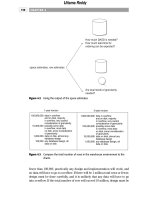
As you add computers to your network, you probably want to use at least one
of them as a server, a computer used to provide network resources. The net-
work in Figure 13-2 with a file and print server might look something like the
one in Figure 13-5. The computers where you work are called client computers
(using the computer industry’s common client/server terminology).
Figure 13-5: Adding a file and print server
The advantage of setting up a server — even on a home network — is that it
keeps the resources you use available no matter what’s happening on any
other client PC. Your brother can be crashing his PC hourly, and no matter
what other PC you’re using, you need not care what he’s doing, because your
File and
print server
Client
computers
Switch
A B C
G F E
DH
Ethernet switch
SwitchHub
SwitchHub
Chapter 13 ✦ Hubs, Switches, Routers, and Firewalls 197
e-mail files and the printer are accessible through the server. So long as no one
sits down at the server and starts using it directly as a PC, it should stay stable
and reliable. Better yet, you can load the server up with huge disks and use that
storage from any PC on your network.
Routers
There comes a point when it’s neither practical nor desirable to keep connect-
ing networks together with Ethernet hubs or switches. You don’t want to con-
nect to a network that is not under your control without some safeguards, and
the connections from LANs to the Internet are rarely direct Ethernet feeds.
Instead, you want a way to link your network to other ones, exchanging mes-
sages when needed but otherwise remaining isolated.
Networks solve these problems using a set of conceptual layers, each serving a
different function. Figure 13-6 shows three layers from a larger structure called
the Open Systems Interconnect (OSI) Reference Model. The layers shown in
Figure 13-6 are the bottom three of seven layers in the full OSI model:
Figure 13-6: The OSI Reference Model structures network
systems design.
✦ Network layer — The network layer tracks interconnected networks
and routes packets among them. The network layer operates inde-
pendently from the media technology layers below it.
✦ Data link layer — The data link layer identifies stations on the medium
and provides low-level control for transmissions between stations. In
an Ethernet network, the data link layer defines unique identifiers for
each station, defines the way in which stations find out each other’s
addresses, and defines the mechanisms for handling collisions.
✦ Physical layer — The transmission media — LANs most commonly
use twisted-pair cables and the electrical drivers for those cables —
form the physical layer. The physical layer converts data to signals
on the network cable and recovers signals from the network back to
data.
Network
The network layer knows about different
interconnected networks and how to route
among them.
Data Link
The data link layer knows how to transfer
data from one node to another.
Physical
The physical layer knows how to put data
on a medium and to recover the data from
the medium at the other end.
198 Part V ✦ Networks and Communications
Figure 13-7 shows how two computers connected back-to-back (as in Figure 13-1)
communicate using the OSI Reference Model. A protocol stack implements the
network layers on each computer. Each layer in the stack interoperates as a
peer with the same layer on the other computer, so the network layer on
Computer A in Figure 13-7 communicates peer-to-peer with the network layer
on Computer B. The two network layers don’t connect directly, though — they
have to send messages back and forth through the data link layer. A lower
level peer relationship exists between the data link layers, which in turn com-
municate with each other by sending messages back and forth using the physi-
cal layer. It’s the physical layers that are actually connected, so they have a
real connection and do communicate directly. These three layers of the model
are just that, however, a model. Real networks correspond roughly to the
model, but have differences and make compromises so the overall system runs
efficiently and economically.
Figure 13-7: Peer layer communication in a network
The key characteristic distinguishing the network layer from the data link layer
is that the network layer is independent of the underlying media characteris-
tics. Devices operating at the data link layer, such as Ethernet switches, exploit
the physical characteristics of Ethernet (and the similarities among the many
versions of Ethernet) to do their work. Devices operating at the network layer,
called routers, transfer network data from one port to the next with no knowl-
edge of the underlying media connected to the interfaces.
Because networks operate at both media-dependent and media-independent
levels, it follows that your computer has both physical and logical (that is,
network) addresses.
✦ The physical address on an Ethernet (also called a MAC address, for
Media Access Control) is a unique number wired into your Ethernet
card by its manufacturer — the physical address for one of our com-
puters, for example, is 00-20-AF-F8-29-B4.
Network
Software
Data Link
Physical
Computer A
Network
Software
Data Link
Physical
Computer B
Network peers
Data link peers
Physical medium
Chapter 13 ✦ Hubs, Switches, Routers, and Firewalls 199
✦ The network address is completely independent of the physical
address — if you change Ethernet cards, for instance, you change the
computer’s physical address but not the network address. Network
addresses for the Internet Protocol (IP) consist (today) of four num-
bers each from 0 to 255, such as
206.142.111.239. Future versions
of IP will add more numbers to those addresses, but the change isn’t
likely for several years.
If you have more than one network interface (a network card and a
modem connected to the Internet, for example), you will have more
than one network address. For example,
206.164.111.239 might be
a network address temporarily assigned to your computer by your
Internet service provider (and therefore assigned to your modem
port), while you might use
192.168.0.1 for your local area network.
To connect two different networks without merging them physically, you need
a device — a router — that joins networks at the network layer, not the data
link layer. Figure 13-8 shows these relationships. Routers contain network-layer
software that connects as a peer to the network software in your computer,
receives messages, decides which port leads to the message’s destination, and
sends the message down to the data link layer in the right protocol stack.
Figure 13-8: The network layer joins otherwise incompatible networks.
Suppose software on your computer needs to send a message to a computer
on the Internet. Your software passes the message to the IP network layer on
your computer, which figures out which of the data links on your computer
leads to the Internet. The message gets handed off to the data link layer for
that interface, passed to the physical layer, and sent down the wire. The physi-
cal layer in the router picks up the message and percolates it up through the
data link layer to the network layer in the router. That software in turn figures
out that the next data link to receive the message is the one leading to the
Internet, and sends it down the protocol stack and on its way.
Network
Software
Data Link
Physical
Computer A
Data Link
Physical
Network
Data Link
Physical
Router
Network peers
Data link peers
Physical medium
Network peers
Data link peers
Physical medium
Local Area Network Wide Area Network
200 Part V ✦ Networks and Communications
The magic is that the IP network layer in the router allows the data link and
physical layers to need peer relationships only with compatible hardware and
software at the other end of a connection. The data link layer and physical
hardware in your computer — an Ethernet card — don’t know and don’t care
that the ultimate connection is out to the Internet, or that that connection is
through a modem and not the Ethernet. Similarly, the modem data link layer
and hardware don’t know and don’t care what your local area network looks
like. The network layer in the router is the only software that has any tie to
both links. This is weapons-grade magic because it means that, no matter what
kind of network you want to attach to your local area network, the right router
(meaning one with the right data link and physical interfaces) can do the job
without any change in your local network.
Transmission Control Protocol
Most of the time, you hear IP, the Internet routing layer, mentioned as part of
TCP/IP, which stands for Transmission Control Protocol/Internet Protocol. The
reason for that is that very little software actually talks to IP directly because
IP itself leaves a lot of network-induced problems unsolved. Protocols above IP,
such as TCP, solve those problems.
The first problem IP has that you need to solve comes from IP’s function, which
is to route information from here to there and back. IP doesn’t guarantee that
your messages will actually arrive at the destination, doesn’t guarantee that
they’ll arrive in the order you sent, and doesn’t give you any indication of
whether the network has the capacity to transmit as much data as you want.
Every one of these problems stems from the nature of the underlying network:
✦ Unreliable delivery — Neither IP nor the Internet itself guarantees
that the data you send will get anywhere. Your Internet connection
could get dropped, the modem could garble the data, a communica-
tions link could be full to capacity, the computer at the other end
could mishandle the message, or a thousand other things could go
wrong. Any one of them can cause your message to get lost.
✦ Out-of-order delivery — IP and the Internet don’t make any promises
about the order in which messages get delivered. Because it takes a
lot of messages across the Internet to do anything useful, they can
arrive in a sequence very different from the one in which they were
transmitted. Most programs send messages and replies in a tightly
defined sequence, so out-of-order delivery would be very confusing.
It would be like getting the check in a restaurant before you’ve even
seen the menu.
✦ Capacity limits — Getting your message sent through your modem
provides no assurance that it’s actually going anywhere. For instance,
suppose your message arrives at a router, but its destination circuit
is already full of traffic. Your message can get dumped if the router
doesn’t have enough memory to hold the incoming messages until
they can get a turn on the output circuit.
Chapter 13 ✦ Hubs, Switches, Routers, and Firewalls 201
Every one of these problems is solvable, and most of the time programs com-
municating on the Internet want them to be solved. It’s not efficient to require
every program that communicates over the Internet to include code to solve
the problems independently — that would mean many, many different imple-
mentations, would increase software costs, and would make interoperability
among programs unlikely. Instead, a protocol layer on top of IP — namely,
TCP — provides these services to programs. A program hands data off to TCP
for transmission, and having done so can assume that the data will make it to
the other end intact and in order. If TCP can’t do that, it explicitly notifies the
program. If there are no error notifications, the program can assume TCP did
its job.
The implementation of how TCP does what it does requires that programmers
handle a mind-numbing set of details, but the ideas behind TCP are pretty
straightforward:
✦ Put sequence numbers in messages — Every message TCP sends
out onto the network gets a sequence number. By looking at the
sequence numbers of messages as they come in, the TCP receiver
can tell whether it has the next message yet, or whether it has to
wait for the network to deliver some out-of-order messages.
✦ Tell the sender when messages arrive — The TCP receiver sends a
message (an acknowledgment) back to the sender when messages
arrive correctly and in sequence, telling the sender the sequence
number of the highest correctly received message.
✦ Retransmit failed messages — The TCP sender keeps a timer for
every message it sends. If the receiver doesn’t acknowledge the mes-
sage within a certain interval of time, the sender retransmits the
message. This process keeps up until TCP has tried a specified num-
ber of retransmissions, after which it reports an uncorrectable failure
to your program.
✦ Retransmit garbled messages — Even if your message gets to its
destination, it might have been corrupted in transmission. TCP uses
error detection codes it wraps around your message to know when
this has happened. When the TCP receiver detects a garbled mes-
sage, it explicitly sends a message back to the sender requesting
retransmission.
Only the garbled (or lost) messages are sent again. If other messages in
the sequence after the bad one arrive properly (even if that happens
before the bad one finally gets there), they don’t need retransmission.
✦ Limit the number of outstanding messages — The TCP sender limits
the number of messages it sends before receiving an acknowledgment,
which has the effect of limiting the average data rate you need on the
connection between you and the destination. More than one message
can be outstanding, however, so in most cases the sender doesn’t have
to wait out the round-trip delay for an acknowledgment to arrive.
Sending multiple messages in advance of acknowledgment greatly
increases the amount of data you can get through the connection.
202 Part V ✦ Networks and Communications
Don’t assume that when someone refers to TCP/IP (including in this book) that
the reference is exclusively to TCP and IP — it’s common usage to call the com-
plete set of Internet protocols TCP/IP.
User Datagram Protocol
The reliable transport services of TCP come at a price. In particular, the need
to wait for acknowledgment messages limits the data rate you can put into the
communications channel. This limitation (along with all the other work TCP
does) creates an additional processing load at both ends of the channel.
Some applications, including Internet phone and videoconferencing, and many
multi-player Internet games, can’t afford the overhead TCP imposes. The vol-
ume of data those applications send and their need for uninterrupted data flow
make the waits TCP can impose for message acknowledgments unworkable.
Take Internet videoconferencing, perhaps using Microsoft’s NetMeeting, as an
example. If your data does get damaged in transit, the worst that’s likely to hap-
pen is that you’ll see a glitch in the video or hear noise in the audio. Slowing
the data transmission — one consequence of what TCP does to provide reli-
able delivery — reduces the frame rate and creates gaps in the sound. Because
your eyes and ears handle noise better than gaps, you’re better off with more
data, even if it contains a few errors.
The situation is about the same for multi-player games across the Internet. The
rapid, timely flow of data between computers is more important than getting
every bit right — the programs mostly send updates to the same data over and
over, so even if you drop a message, it won’t matter.
The Internet protocols solve this problem by replacing TCP with the User
Datagram Protocol (UDP), which does none of the corrective things TCP does.
UDP does not provide in-order delivery, acknowledgments, retransmissions, or
flow control. It’s relatively basic, but in exchange for that simplicity UDP gets
more data sent for a given link capacity and imposes less workload on the
processor.
Domain Name Service
A usable network needs to do a few more things than move messages around.
One of the most important is providing a way to translate the computer names
people deal with (for example,
www.theonion.com) to the numbers computers
want to see (such as
66.216.104.235). The Internet function that does this
for you is called the Domain Name Service. Computers providing that service
are called domain name servers. Both phrases are abbreviated DNS.
Internet domains are a hierarchical structure based on the words you find
separated by dots in computer names. The last word in the computer name
(for example,
com) is the least specific part of the domain name, called the
top-level domain name. Common top-level domains include
.com, .org, and
.net, plus ones for each country; there’s a reasonably comprehensive list at
www.norid.no/domenenavnbaser/domreg.html.
Chapter 13 ✦ Hubs, Switches, Routers, and Firewalls 203