Ethernet Networks: Design, Implementation, Operation, Management 4th phần 5 potx
Bạn đang xem bản rút gọn của tài liệu. Xem và tải ngay bản đầy đủ của tài liệu tại đây (607.06 KB, 60 trang )
226 chapter five
Application program(s)
LAN overlay
software
DOS 3.0
or below
DOS 3.1
or above
BIOS
Proprietary
network BIOS
IBM PC net-
work program
PC adapter
with NETBIOS
BIOS
LAN adapter card
IBM PC LAN
program
DOS 3.1
or above
NETBIOS BIOS
Token-ring
adapter card
Ethernet
adapter card
Figure 5.20 Original PC LAN hardware and software relationships in an IBM
PC environment.
With the introduction of IBM’s first local area network, referred to as the
PC Network, in August 1984, IBM released all three components required
to implement an IBM local area network using IBM equipment: the IBM PC
Network Program, PC DOS 3.1, and the IBM PC Network Adapter. The IBM PC
Network Program was actually a tailored version of Microsoft Corporation’s
Microsoft Networks (MS-NET) software, which is essentially a program that
overlays DOS and permits workstations on a network to share their disks and
peripheral devices. DOS 3.1, also developed by Microsoft, added file- and
record-locking capabilities to DOS, permitting multiple users to access and
modify data. Without file- and record-locking capabilities in DOS, custom
software was required to obtain these functions — without them, the last
person saving data onto a file would overwrite changes made to the file by other
persons. Thus, DOS 3.1 provided networking and application programmers
with a set of standards they could use in developing network software.
Included on the IBM PC Network Adapter card in ROM is an extensive
number of programming instructions, known as NetBIOS. The middle portion
of Figure 5.18 illustrates the hardware and software components of an IBM
PC LAN network.
When the IBM Token-Ring Network was introduced, NetBIOS was removed
from the adapter card and incorporated as a separate software program,
activated from DOS. The right-hand column of Figure 5.18 illustrates this new
relationship between hardware and software. At first, NetBIOS was d esigned
to operate with Token-Ring adapter cards. Later, IBM extended NetBIOS to
work with CSMA/CD Ethernet adapter cards.
networking hardware and software 227
Due to the standardization of file-and-record locking under DOS 3.1, any
multiuser software program written for DOS Version 3.1 or later will run on
any LAN that supports this version of DOS. Although DOS 3.1 supports many
networking functions, it was not a networking operating system. In fact, a
variety of networking operating systems support DOS 3.1 and later versions
of DOS, including MS-NET, IBM’s PC Network Program, IBM’s Token-Ring
Program, Microsoft’s Windows NT, and Novell’s NetWare. You can therefore
select a third-party network operating system to use with IBM or non-IBM
network hardware, or you can consider obtaining both third-party hardware
and software to construct your local area network.
Network Operating Systems
A modern network operating system operates as an overlay to the personal
computer’s operating system, providing the connectivity that enables per-
sonal computers to communicate with one another and share such network
resources as hard disks, CD-ROM jukebox drives, and printers, and even obtain
access to mainframes and minicomputers. Four of the more popular LAN
operating systems are Microsoft Corporation’s Windows NT, its successors,
Windows 2000 and Windows XP, and Novell Corporation’s NetWare.
Both versions of Windows and NetWare are file server–based network
operating systems. This means that most network modules reside on the file
server. A shell p rogram loaded into each workstation works in conjunction
with the server modules. The shell program workstation filters commands,
directing user-entered commands to DOS or to the network modules residing
on the server. Communications between the shell and the server modules
occur at the OSI Reference Model’s Network Layer. Microsoft’s Windows
uses NetBIOS Extended User Interface, commonly referred to as NetBEUI,
which is automatically installed when the operating system is installed, while
Novell’s NetWare uses its Internetwork Packet Exchange (IPX) protocol as the
language in which the workstation communicates with the file server. Both
Windows and NetWare support the concurrent use of multiple protocols. For
example, Windows includes built-in support for TCP/IP, NWLink, and Data
Link control. Until the mid-1980s, it was difficult to support more than one
protocol at a time due to the manner by which network software residing on
a workstation or server communicated with one or more software modules
known as the protocol stack. Once we examine the manner by which a client
gains access to a server and obtain an overview of NetWare and Windows, we
will then turn our attention to the method by which multiple stacks can be
employed to support multiple protocols.
228 chapter five
Services
The process by which the shell enables a workstation to communicate with
a set of services residing on a server is known as a client/server relationship.
Services provided by network modules on the server can range in scope from
file access and transfer, shared printer utilization, and printer queuing to
electronic mail. Other features available in most network operating systems
include the ability to partition disk storage and allocate such storage to
different network users, and the assignment of various types of security levels
to individual network users, groups of users, directories, files, and printers.
Some network operating systems include a disk mirroring feature and a remote
console dial-in capability.
Because file information in the form of updated accounting, payroll, and
engineering d ata can be critical to the health of a company, it is often very
important to h ave duplicate copies of information in case a hard disk should
fail. Disk mirroring is a feature that duplicates network information on two
or more disks simultaneously. Thus, if one disk fails, network operations
can continue.
A remote console dial-in capability enables a network user to gain access
to the network from a remote location. This feature can be particularly
advantageous for people who travel and wish to transmit and receive messages
with people back at the office or obtain access to information residing on
the network. Because the administration of a network can be a complex
process, a remote dial-in feature may also make life less taxing for a network
administrator. Working at home or at another location, the administrator can
reassign privileges and perform other network functions that may n ot be
possible in an eight-hour day.
Looking at NetWare
Because the best way to obtain information concerning the relationship of a
network operating system to network hardware is to examine the software,
we will do so. We will discuss Novell Corporation’s NetWare and Microsoft’s
Windows, as those network operating systems (NOS) are by far the most
popular of all network operating systems used.
Architecture
The architecture or structure of NetWare can be mapped to the OSI Reference
Model. It provides an indication of the method by which this network operat-
ing system provides support for different types of hardware, and includes the
networking hardware and software 229
ApplicationApplication
Presentation
Session
Transport
Network
Data link
Physical
OSI
reference
model
Netware
Net BIOS
emulation
Netware
shell
(workstation)
Netware
Core protocol
(NCP)
(on server)
Sequenced packet exchange (SPX)
Internet packet exchange
(IPX)
Token-ring Ethernet ARCnet Others
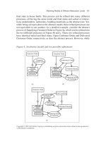
Figure 5.21 NetWare and the OSI Reference Model.
capability for the routing of packets between networks. Figure 5.21 illustrates
the general relationship between NetWare and the OSI Reference Model.
In examining Figure 5.21, note that NetWare supports numerous types of
local area networks. This means that you can use NetWare as the network
operating system on Ethernet, Token-Ring, ARCnet, and other types of net-
works. In fact, NetWare also supports different types of personal computer
operating systems, such as DOS, O S/2, different versions of Windows, UNIX,
and Macintosh. This means that NetWare is capable of supporting differ-
ent types of local area networks as well as workstations that use different
operating systems.
Using NetWare on a PC requires the loading of two Novell files whenever
you turn on your computer or perform a system reset. Those files are IPX and
NETx, where x indicates a specific version of the NET file used with a specific
version of DOS, such as NET3 used with DOS 3.
The use of IPX and NETx are required through NetWare Release 3.11.
In Release 3.12 and in NetWare Version 4.X and later versions of this net-
work operating system, NETx was replaced by the use of a virtual loadable
module (VLM). Later in this section, we will discuss the use of NetWare’s
VLM.EXE program.
Both IPX and NET are workstation shell programs that interpret and filter
commands entered from the keyboard and provide a mechanism for communi-
cations between the workstation and the server. Before NetWare Version 2.1,
the shell was known as ANET3.COM, and was combined with IPX and NETx
into one file. Later versions of NetWare separated IPX from NETx.
230 chapter five
To automate the loading of NetWare on your workstation to establish a
network connection, you would normally insert appropriate commands into
your computer’s AUTO-EXEC.BAT file. Those commands would include:
IPX
NETx
F:
LOGIN <servername/username>
IPX The command IPX would cause Novell’s IPX.COM file to be loaded
and executed. This file is a driver that establishes communications with the
network interface board, and it is responsible for providing communications
with servers and other stations on the n etwork using a network protocol known
as IPX. At the network layer, Novell’s IPX protocol performs addressing and
internet routing functions. To accomplish this, an IPX packet contains both
the source and destination network addresses. Those addresses are assigned
by a network administrator, and they provide the mechanism for the routing
of data between networks by routers which examine the network layer.
IPX is a connectionless network layer protocol that does not guarantee the
delivery of data. To provide a reliable delivery mechanism, Novell devel-
oped its Sequenced Packet eXchange (SPX) — a transport level interface that
provides a connection-oriented packet delivery service.
NCP At the session and presentation layers, NetWare uses a NetBIOS emu-
lator, which provides an interface between application programs written in
compliance with NetBIOS and NetWare. As previously mentioned, the Net-
Ware shell operates on each workstation and communicates with a core set
of modules that reside on servers. That core set of modules is known as
the NetWare Core Protocol (NCP). NCP provides such functions as worksta-
tion and network naming management, file partitioning, access and locking
capabilities, accounting, and security.
NET The command NETx loads NETx.COM, which is the true workstation
shell, because it interprets and filters commands entered from the keyboard.
In addition, NETx supports a large number of NetWare commands, which,
when entered, are converted into IPX packets and transmitted to the server
for processing. The NetWare Core Protocol decodes the command request,
processes the request, and then transmits a response to the workstation using
one or more IPX packets. The workstation’s NET module then processes and
displays the response. For example, typing the NetWare command CHKVOL at
the workstation transmits a request to the server to obtain statistics concerning
the logical driver (volume) assigned to the workstation user. The results of that
networking hardware and software 231
request are transmitted back to the workstation and displayed on its screen
the same way a DOS CHKDSK command is displayed.
When the shell (NETx) is loaded, it normally establishes a connection to a
network server by sending a request to IPX to broadcast a Get Nearest Server
command. The first server that responds to the request then establishes a
connection to the workstation and displays the message ‘‘Attached to server
<servername>’’ on your computer’s console. You can also specify a preferred
server by adding the P S = parameter to the NETx command; this provides you
with the ability to distribute workstation server usage over a number of servers.
Once a connection to a NetWare server occurs, the command F: in the
AUTOEXEC.BAT file moves the workstation user to the server’s SYS:LOGIN
directory. That directory is designated or mapped to drive F: on your DOS-
operated workstation. Once this is accomplished, the command LOGIN
initiates the LOGIN module on the server. If you include the servername
and username, LOGIN will then request only your password to obtain access
to the server.
Versions Several versions of NetWare have been marketed during the past
ten years. NetWare 286, which was renamed NetWare 2.2, was designed to
operate on Intel 286–based servers. This operating system supported up to
100 users. NetWare 386 (renamed NetWare 3.1), operated on Intel 386–based
servers. This network operating system supported up to 250 users.
The introduction of NetWare 4.0 and the release of NetWare 4.1, followed
by releases 5.0 and 6.0, extended Novell’s NetWare support to local area
networks consisting of up to several thousand workstations. As previously
discussed, NetWare 3.12 as well as all versions of NetWare 4.X resulted
in the replacement of NETx by the virtual loadable module VLM.EXE. By
including the command VLM.EXE in your AUTOEXEC.BAT file, you would
cause the executable virtual loadable module to be loaded. This executable file
will automatically load a number of files with the .VLM extension, tailoring
NetWare to your workstation.
A second change to NetWare is the fact that in November 1991 Novell
ceased supporting its dedicated IPX driver. IPX was specific to the network
interface card and version of NetWare being used on a workstation, and
required you to create a new version each time you installed a new network
card. A second problem associated with IPX is the fact that once used
with an adapter card, you cannot use another protocol with that card. For
example, if you want to communicate using TCP/IP to a UNIX server with
the same card, you would have to change your AUTOEXEC.BAT file, remove
or comment out via REM statements your invocation of IPX and NETx, add
232 chapter five
your TCP/IP commands, and reboot your computer. Obviously this was not a
pleasant situation.
Recognizing the preceding problems, Novell released a new architecture
known as the Open Data-Link Interface (ODI) in 1989. By 1991, ODI became
the only IPX standard interface supported by Novell. Through the use of
ODI, you can support multiple protocols through a common adapter without
requiring the rearrangement of statements in your AUTOEXEC.BAT file and
rebooting your computer. To do so, you must obtain the following special
files — LSL, IPXODI, and an interface driver. LSL is a link support layer
program that you must obtain from Novell. The interface driver is provided
by the manufacturer of the adapter card, while IPXODI is furnished by both
Novell and the adapter card manufacturer.
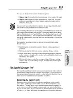
Figure 5.22 illustrates the relationship of the three previously mentioned
programs when a multiprotocol or dual stack operation is desired. The inter-
face driver provides low-level I/O operations to and from the adapter card,
and passes information received from the LAN to the Link Support Program.
That program examines incoming data to determine if it is NetWare (IPX) or IP
(TCP/IP) in the example illustrated in Figure 5.22. LSL then passes received
data to the appropriate stack. Thus, IPXODI represents a modification to IPX,
which permits it to interface Novell’s LSL program.
Although LSL resides on top of the interface driver, you must load it before
loading that driver. Thus, your AUTOEXEC.BAT file would have the following
generic entries to support ODI on your workstation:
LSL
HRDRIVER
IPXODI
NETx
IPXODI
TCP/IP
Link support layer
(LSL)
Interface driver
Network adapter card
Figure 5.22 Multiprotocol support using Nov-
ell’s ODI.
networking hardware and software 233
NETX
F:
LOGIN
In examining the preceding entries, note that HRDRIVER would be replaced
by the actual name of your adapter card’s interface driver. In addition, under
NetWare 3.12 and 4.X and later versions of this operating system, you would
replace NETx with VLM.
To add the TCP/IP protocol stack under DOS you would add the appropriate
statements to your AUTOEXEC.BAT file. Those statements must follow the
execution of LSL.COM but can either precede or succeed the statements u sed
to invoke the N etWare protocol stack. For example, assume NetWare files
are located in the NetWare directory and the appropriate packet driver is
contained in the file ODIPKT and the TCP/IP program is contained in the file
TCPIP, while both the ODIPKT and TCP/IP files are located in the directory
TCP. Then, the AUTOEXEC.BAT fi le would contain the following statements
with the REM(ark) statements optionally added for clarity.
REM *Install NetWare*
C:\NETWARE\LSL.COM
C:\NETWARE\LANDRIVER
C:\NETWARE\IPXODI.COM
C:\NETWARE\NETx.EXE
F:
LOGIN GHELD
REM *Install TCP/IP*
C:\TCP\ODIPKT
C:\TCP\TCPIP
NET.CFG One important file not shown in Figure 5.22 and until now not
discussed is NET.CFG. This file describes the network adapter card configu-
ration to the ODI driver and should be located in the same directory as the
IPXODI and NETx fi les. However, through the use of an appropriate PATH
statement you can actually locate NET.CFG anywhere you desire.
NET.CFG is an ASCII text file that can contain up to four main areas of
information, which describe the environment of a workstation. Those areas
include a link support area, protocol area, link driver area, and parameter area.
Link Support Area The link support area is used to define the number
of communications buffers and memory set aside for those buffers. This
area is required to be defined when running TCP/IP, however, because
234 chapter five
IPX does not use buffers or memory pools maintained by LSL you can
skip this section if you are only using a NetWare protocol stack. The
following illustration represents an example of the coding of the link sup-
port area in the NET.CFG file to support TCP/IP. The actual coding you
would enter depends upon the network adapter card to be used and you
would obtain the appropriate information from the manual accompanying the
adapter card.
LINK SUPPORT
BUFFERS 8 1144
MemPool 4096
MaxStacks 8
Protocol Area The protocol area is used to bind one or more protocols
to specific network adapter cards. By default, IPXODI binds to the net-
work adapter in the lowest system expansion slot as it scans slots in their
numeric order. If you have two or more network adapter cards in a work-
station, you can use the protocol area to specify which protocols you want
to bind to each card. You can also accomplish this at the link driver area
by specifying Slot n,wheren is the slot number of the network adapter
card you are configuring. Assuming you wish to bind IPX to an adapter
card whose address is h123, you would add the following statements to the
NET.CFG file.
Protocol
PROTOCOL IPX
BIND h123
Because each computer using TCP/IP requires an IP address, the IP address
information must be included in the NET.CFG file if you intend to use
the TCP/IP protocol stack. For example, if the network administrator assigned
your computer the IP address 133.49.108.05, the IP address information would
be entered as follows:
PROTOCOL TCP/IP
ip
−
address 133.49.108.05
When using TCP/IP, each workstation on the network is assigned the
address of a default router (commonly referred to as a gateway) by the network
administrator. Thus, another statement commonly added to the NET.CFG file
includes the address of the router that the workstation will use. For example,
networking hardware and software 235
if the router’s address is 133.49.108.17, then you would add the following
statement to the NET.CFG file in its protocol area.
ip
−
router 133.49.108.17
The ip
−
address and ip
−
router statements can be avoided if the network
administrator sets up a Reverse Address Resolution Protocol (RARP) server
configured with IP and hardware addresses for workstations on the network.
Then, when the workstation is powered on it will broadcast an RARP packet
that will contain its hardware address. The RARP server will respond with
the workstation’s IP address associated with the hardware address.
Link Driver Area The link driver area is used to set the hardware configura-
tion of the network adapter card so it is recognized by LAN drivers. If you are
only using Novell’s IPX, the first line of your NET.CFG file is a LINK DRIVER
statement which tells NETX the type of LAN card installed in the workstation,
such as
Link Driver 3C5X9
The reason this statement becomes the first statement is because the link
support area is omitted and, if you only have one adapter card, you do not
require a protocol area.
If you’re using an NE 2000 Ethernet card, your link driver area would appear
as follows:
Link Driver NE2000
INT 5
PORT 300
Frame Ethernet
−
802.3
Frame Ethernet
−
II
Protocol IPX 0 Ethernet
−
802.3
Protocol IP 8137 Ethernet
−
II
In this example the frame statements define the types of frames that will be
supported by the adapter cards. Although most adapter cards include software
that automatically construct or modify the NET.CFG file, upon occasion you
may have to customize the contents of that file. To do so you can use the
manual accompanying the network adapter card, which will normally indicate
the statements required to be placed in the file.
236 chapter five
Virtual Loadable Modules The introduction of NetWare 4.0 resulted in the
replacement of NETX by VLMs that sit behind DOS. In comparison, NETX
sat in front of DOS and acted as a filter to identify and act upon network
requests entered from the keyboard. VLMs are referred to as the NetWare DOS
Requester as they use DOS redirection to satisfy file and print service requests.
Because VLMs replace NETX.EXE, you would load VLM.EXE in the position
previously used for NETX.EXE. That is, the sequence of commands placed
in your AUTOEXEC.BAT file to initialize the NetWare protocol stack would
appear as follows:
C:\NETWARE\LSL
C:\NETWARE\LANDRIVER
C:\NETWARE\IPXODI
C:\NETWARE\VLM.EXE
F:
LOGIN GHELD
To modify the AUTOEXEC.BAT fi le to support dual-stack operations you
could add the appropriate commands either after invoking LSL or after the
‘‘Login’’ statement.
Looking at Windows
Windows, to include workstation and server versions of NT, 2000 and XP,
represents both a computer operating system and network operating system
that can function together or independently. The basic networking p rotocol
used by each version of Windows is NetBEUI, which provides a network user
interface for local workstations and servers.
NetBIOS The NetBIOS Extended User Interface (NetBEUI) represents an
extension of PC BIOS to the network. NetBIOS was originally developed by
IBM as a simple network protocol for interconnecting PCs on a common
network. The naming structure of the p rotocol results in names assigned to
devices being translated into network adapter card (that is, MAC) addresses.
This results in NetBIOS operating at the data link layer. In addition, because
the NetBIOS naming structure is nonhierarchical, there is no provision for
specifying network addresses. Due to this, NetBIOS is considered to be
nonroutable. Thus, the initial method used to join two or more NetBIOS
networks together was restricted to bridging.
NetBEUI Recognizing the routability problem of NetBIOS, NetBEUI allows
data to be transported by a transport protocol to obtain the ability to
networking hardware and software 237
interconnect separate networks. In fact, NetBEUI can be transported by
TCP/IP and even IPX/SPX. To accomplish this, NetBEUI maintains a table
of NAMES that are associated with TCP/IP addresses when TCP/IP is
used as a transport protocol, and a similar table matched to NetWare net-
work addresses and station MAC addresses when NetBEUI is transported
via IPX/SPX.
To illustrate the operation of a few of the capabilities of Windows net-
working, we will briefly use a Windows NT workstation and a Windows NT
server to illustrate the installation of network software and adapter cards.
In addition, we will use a Windows NT workstation to display the servers
on a network where both NT and NetWare servers reside, transferring a file
from an NT workstation to a Novell file server. Both NetWare and Win-
dows NT can communicate on a common network, because NT supports the
NWLink protocol that provides communications compatibility with NetWare’s
IPX/SPX protocol.
Adapter and Software Support Windows workstation and server products
use common methods to add support for network software and adapter cards.
Although the screen display for configuring network software and adapter
cards varies between versions of Windows, the basic methods remain the
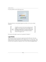
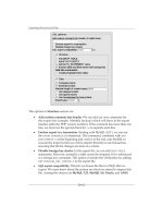
same. Thus, although Figure 5.23 illustrates the network settings screen for
Version 3.51 of NT, the basic methods we will describe are also applicable to
other versions of NT, Windows 2000 and Windows XP.
In examining Figure 5.23, note that five network software modules are
shown in the upper box labeled Installed Network Software, and one adapter
card is shown as being installed in the lower box labeled Installed Adapter
Card. Windows supports the binding of multiple protocols to a common
adapter via the use of the network driver interface specification (NDIS), which
will be described at the end of this section. You can add network software,
such as TCP/IP, by clicking on the Add Software button shown in Figure 5.23.
This action will result in the d isplay of a list of networking software directly
supported by Windows. Similarly, if you want to add another adapter you
would click on the Add Adapter button. If the adapter you wish to add is
not directly supported by Windows, you can select the option ‘‘Other — have
disk’’ at the end of the list of supported adapters. This will allow you to add
support for a wide range of NICs that are commonly shipped with Windows
drivers, but which are not directly supported by the version of Windows you
are using.
Network Operation Figure 5.24 illustrates the use of F ile Manager on a
Windows NT workstation to view the names of devices on both a Windows
238 chapter five
Figure 5.23 Using the Windows NT dialog box to review, add, or change
network software and adapter card support.
Figure 5.24 Viewing devices on both a Windows and a Novell network
through the Windows NT File Manager.
networking hardware and software 239
Figure 5.25 Selecting a path to a directory on a Novell server that will be
mappedtodriveEonalocalworkstation.
network and a NetWare network. Figure 5.25 illustrates the result obtained by
first selecting an appropriate NetWare server and then selecting a directory
on that server that we wish to access. This action will result in the mapping
of drive E on the local workstation to the path shown in Figure 5.25. Once we
enter the appropriate connection information, drive E on the local Windows
NT workstation will be mapped to the directory FRED located under the
directory SYS on the server MDPC-1.
After we correctly log onto the server, we can run network applications
or transfer data to or from the server. Figure 5.26 illustrates how you could
select ‘‘Move’’ from the File menu and enter the command c:\funds\*.* to
move all files under the subdirectory FUNDS on the local workstation to the
network server.
NDIS Operation Considerations Similar to the manner by which Novell
developed an architecture for supporting multiple protocols via a common
adapter, Microsoft developed a competing standard referred to as NDIS. In this
240 chapter five
Figure 5.26 Using File Manager to move all files in the directory FUNDS on
the local workstation to the directory FRED on the file server.
section we will focus our attention upon obtaining an overview of the structure
of NDIS, even though it is well-hidden from view when you use a Windows
operating environment. Although NDIS provides a dual-stack capability sim-
ilar to that provided by ODI, its setup for operation varies considerably from
the previously discussed dual-stack mechanism. Figure 5.27 illustrates the
Protocol
stack
Protocol
stack
LAN support program(s)
NDIS protocol manager
Network adapter driver
Network adapter card
N
D
I
S
Figure 5.27 NDIS architecture.
networking hardware and software 241
relationship between NDIS software modules, upper-layer protocol stacks,
and the network adapter card.
CONFIG.SYS Usage Unlike ODI, which represents a series of files loaded
from an AUTOEXEC.BAT file, NDIS was designed as a series of device drivers
that are loaded through the CONFIG.SYS file. In a DOS environment the first
statement in the CONFIG.SYS file required for NDIS is:
DEVICE=drive:\path\PROTMAN.DOS
PROTMAN.DOS represents the NDIS Protocol Manager for each workstation
operating DOS. The Protocol Manager reads the file PROTOCOL.INI, which
contains initialization parameters and stores the contents of that file in memory
for use by other NDIS drivers. Thus, a short discussion of PROTOCOL.INI file
is in order.
PROTOCOL.INI Overview The PROTOCOL.INI file can be considered to
represent the NDIS equivalent of the N ET.CFG file associated with ODI.
Although most network products including various versions of Windows will
automatically create or modify the PROTOCOL.INI file, some p roducts require
users to create or modify that file. In addition, you may be able to enhance
network performance by modifying an existing parameter set by a network
program that does not consider your total user environment.
Entries in PROTOCOL.INI occur in sections, with each section name sur-
rounded in brackets ([]). Under each section name are one or more named
configuration entries, which appear in the format ‘‘name = value’’. Although
configuration entries can appear anywhere in a line under the section name,
normal practice is to indent each entry three character positions to enhance
readability.
Depending upon the version of Windows you are using, the first section in
the PROTOCOL.INI file may have the heading [PROTMAN
−
MOD]. The first
configuration entry for DOS is the device name PROTMAN$. Thus, the first
section entry becomes:
[PROTMAN
−
MOD]
DriverName = PROTMAN
Other versions of Windows may commence with an NDIS help section
followed by the PROTMAN
−
MOD section.
Other entries in the [PROTMAN
−
MOD] section are optional and can include
keywords Dynamic, Priority, and Bindstatus in assignment statements. The
242 chapter five
Dynamic statement can be set to ‘‘YES’’ (Dynamic = YES) to support both static
and dynamic binding or ‘‘NO’’ (Dynamic = NO) to set the Protocol Manager
to operate only in static mode, which is its default. In static mode protocol
drivers are loaded once at system initialization and remain in memory. In
the dynamic mode drivers load at the point in time when they are bound by
Protocol Manager. In addition, if the drivers support a dynamic unloading
capability they can be unloaded if the software unbinds them when they are
not needed, freeing memory.
The Priority keyword is used to specify the order of priority of protocol
processing modules. Under NDIS an incoming LAN packet is first offered to
the protocol with the highest priority. Other protocols will see the packet only
if a higher protocol does not first recognize and process the packet. Protocols
not specified in a priority list are the last to inspect incoming packets.
The Bindstatus keyword is used to specify whether Protocol Manager can
optimize memory and can be set to ‘‘YES’’ or ‘‘NO’’. If the keyword is not
used, a default of ‘‘NO’’ is assumed.
The second communications statement included in a CONFIG.SYS file for
NDIS operations invokes the network adapter card driver. For example, if you
were using the NE2000 adapter, you would include the following statement
in the CONFIG.SYS file.
DEVICE=[drive:]\path\NE2000.DOS
NDIS Adapter Support The adapter driver, which is compatible with the
NDIS Protocol Manager, is referred to as an NDIS MAC driver. The NDIS
MAC driver is normally contained on a diskette that is included in a box
in which your NDIS-compatible network adapter is packaged. When using
Windows NT the operating system includes built-in NDIS support for approx-
imately 30 adapter cards. A s previously explained, if the adapter you are
using is not directly supported by Windows NT, you would select the
Other option from the install adapter card entry from the network con-
figuration display obtained from the Windows Control Panel. Then you
would use the diskette that accompanies your adapter card to install the
required driver.
Once you install your adapter card and appropriate communications pro-
tocols under Windows, the operating system will automatically connect the
software layers as required to form appropriate protocol stacks. Microsoft
refers to this as network bindings, and Figure 5.28 illustrates an example
of the NT N etwork Bindings display after a large number of protocols
were installed.
networking hardware and software 243
Figure 5.28 Viewing an example of the Windows NT Network Bindings
display.
Application Software
The third major component of software required for productive work to
occur on a local area network is application software. These application
programs support electronic mail, multiple access to database records, or
the use of spreadsheet programs; they operate at the top layer of the OSI
Reference Model.
Until the mid-1980s, most application programs used on LANs were not
tailored to operate correctly in a multiuser environment. A large part of their
inability to work correctly was due to the absence of file- and record-locking
capabilities on PC operating systems — a situation that was corrected with
the introduction of DOS 3.1. A second problem associated with application
programs occurred when the program was written to bypass the personal
computer’s BIOS. Although this action in many instances would speed up
screen displays, disk access, and other operations, in this case it resulted in
nonstandardized program actions. This made it difficult, if not impossible, for
some network operating systems to support ill-defined programs, because an
interrupt clash could bring the entire network to a rapid halt.
Today, most application programs use BIOS calls and are well defined. Such
programs are easily supported by network operating systems. A few programs
that bypass BIOS may also be supported, because the application program
that caused operating system vendors to tailor their software to support such
applications was so popular.
244 chapter five
5.4 The TCP/IP Protocol Suite
No discussion of networking hardware and software related to Ethernet
would be complete without covering the TCP/IP protocol suite. Although
the development of TCP/IP occurred at the Advanced Research Projects
Agency (ARPA), which was funded by the U.S. Department of Defense, while
Ethernet traces its origin to the Xerox Palo Alto Research Center, within a
short period of time the two were linked together. Ethernet frames provide
the data link (layer 2) transportation mechanism for the delivery of network
layer (layer 3) IP and transport layer (layer 4) TCP packets that transport such
application data as file transfer, remote access, and Web server information on
an intra-LAN basis. In comparison, TCP/IP provides the mechanism to route
data between LANs and convert IP addresses used by the protocol suite to
MAC addresses used by Ethernet so that TCP/IP packets can be delivered by
Ethernet frames.
Overview
TCP/IP represents a collection of network protocols that provide services at
the n etwork and transport layers of the ISO’s OSI Reference Model. Originally
developed based upon work performed by the U.S. Department of Defense
Advanced Research Projects Agency Network (ARPANET), TCP/IP is also
commonly referred to as the DOD protocols or the Internet protocol suite.
Protocol Development
In actuality, a reference to the TCP/IP protocol suite includes applications that
use the TCP/IP protocol stack as a transport mechanism. Such applications
range in scope from a remote terminal access program known as Telnet to a file
transfer program appropriately referred to as FTP, as well as the Web browser
transport mechanism referred to as the HyperText Transport Protocol (HTTP).
The effort behind the development of the TCP/IP protocol suite has its roots
in the establishment of ARPANET. The research performed by A RPANET
resulted in the development of three specific protocols for the transmission of
information — the Transmission Control Protocol (TCP), the Internet Protocol
(IP), and the User Datagram Protocol (UDP). Both TCP and UDP represent
transport layer protocols. Transmission Control Protocol provides end-to-end
reliable transmission while UDP represents a connectionless layer 4 transport
protocol. Thus, UDP operates on a best-effort basis and depends upon higher
layers of the protocol stack for error detection and correction and other
networking hardware and software 245
functions associated with end-to-end reliable transmission. Transmission
Control Protocol includes such functions as flow control, error control, and
the exchange of status information, and is based upon a connection being
established between source and destination before the exchange of information
occurs. Thus, TCP provides an orderly and error-free mechanism for the
exchange of information.
At the network layer, the IP protocol was developed as a mechanism to
route messages between networks. To accomplish this task, IP was developed
as a connectionless mode network layer protocol and includes the capability
to segment or fragment and reassemble messages that must be routed between
networks that support different packet sizes than the size supported by the
source and/or destination networks.
The TCP/IP Structure
TCP/IP represents one of the earliest developed layered communications pro-
tocols, grouping functions into defined network layers. Figure 5.29 illustrates
ISO Layers
5−7
4
3
2
FTP TELNET SMTP DNS NFS SNMP
UDPTCP
ICMP
IP
ARP
Ethernet 802.3 FDDIToken ring 802.5
Legend:
ARP = Address Resolution Protocol
DNS = Domain Name Service
FDDI = Fiber Data Distributed Interface
FTP = File Transfer Protocol
NSF = Network File System
SMTP = Simple Mail Transfer Protocol
SNMP = Simple Network Management Protocol
Figure 5.29 TCP/IP protocols and services.
246 chapter five
the relationship of the TCP/IP protocol suite and the services they provide
with respect to the OSI Reference Model. In examining Figure 5.29 note that
only seven of literally hundreds of TCP/IP application services are shown.
Because TCP/IP preceded the development of the OSI Reference Model, its
developers grouped what are now session, presentation, and application lay-
ers that correspond to layers 5 through 7 of the OSI Reference Model into
one higher layer. Thus, TCP/IP applications, when compared with the OSI
Reference Model, are normally illustrated as corresponding to the upper three
layers of that model. Continuing our examination of Figure 5.29, you will note
that the subdivision of the transport layer indicates which applications are
carried via TCP and those that are transported by UDP.
As we will note later in this section, TCP represents a connection-oriented
error-free transport protocol. This means that it is well suited for transporting
applications that require the acknowledgement of the availability of a distant
device prior to the actual transfer of data, such as a file transfer application. In
comparison, UDP represents a best-effort, unreliable transport protocol. This
means that UDP can immediately be u sed to transport data without requiring
a prior handshaking operation to be successful. This also means that data is
transmitted under UDP without error detection and correction, making the
application responsible for deciding if this is needed.
Thus, FTP, Telnet, HTTP, and SMTP represent applications transported
by TCP that require a connection to be established prior to data being trans-
ported and need an error detection and correction capability. Domain Name
Service (DNS), Network File System (NFS), and Simple Network Management
Protocol (SNMP) represent applications that do not require a prior connection
and occur on a best effort basis. Thus, DNS, NFS and SNMP are transported
via UDP.
While the prior examples of TCP and UDP usage are well defined, it should
be noted that some applications, such as Internet Telephony, use both trans-
port protocols. For example, call control information such as a dialed number
must flow through the Internet error-free and are carried via TCP. In compari-
son, real-time digitized voice cannot be retransmitted when errors are detected
since this would result in awkward delays at the receiver. Thus, the actual
digitized voice portion of an Internet Telephony call is transported via U DP.
Although not officially layer 3 protocols, both the Address Resolution Pro-
tocol (ARP) and the Internet Control Message Protocol (ICMP) reside in a
‘‘gray’’ area and are commonly shown as residing at that location, so we will
also do this. In addition, because ICMP, as we will shortly note, is transported
with an IP header, it makes sense to consider it residing within layer 3 of the
TCP/IP protocol stack.
networking hardware and software 247
Returning to our examination of Figure 5.29, note that TCP/IP can be
transported at the data link layer by a number of popular LANs, to include
Ethernet, Fast Ethernet, Gigabit Ethernet, Token-Ring, and FDDI frames. Due to
the considerable effort expended in the development of LAN adapter cards to
support the bus structures used in Apple MacIntosh, IBM PCs and compatible
computers, DEC Alphas and SUN Microsystem’s workstations, and even IBM
mainframes, the development of software-based protocol stacks to facilitate
the transmission of TCP/IP on LANs provides the capability to interconnect
LAN-based computers to one another whether they are on the same network
and only require the transmission of frames on a common cable, or if they are
located on networks separated thousands of miles from one another. Thus,
TCP/IP represents both a local and wide area network transmission capability.
Datagrams versus Virtual Circuits
In examining Figure 5.29 you will note that IP provides a common layer 3
transport for TCP and UDP. As briefly noted earlier in this section, TCP
is a connection-oriented protocol that requires the acknowledgment of the
existence of the connection and for packets transmitted once the connection
is established. In comparison, UDP is a connectionless mode service that
provides a parallel service to TCP. Here datagram represents a term used to
identify the basic unit of information that represents a portion of a message
and that is transported across a TCP/IP network.
A datagram can be transported either via an acknowledged connection-
oriented service or via an unacknowledged, connectionless service, where
each information element is addressed to its destination and its transmission
is at the mercy of network nodes. IP represents an unacknowledged connec-
tionless service; however, although it is an unreliable transmission method,
you should view the term in the context that delivery is not guaranteed
instead of having second thoughts concerning its use. As a nonguaranteed
delivery mechanism IP is susceptible to queuing delays and other problems
that can result in the loss of data. However, higher layers in the protocol suite,
such as TCP, can provide error d etection and correction, which results in the
retransmission of IP datagrams.
Datagrams are routed via the best path available to the destination as the
datagram is placed onto the network. An alternative to datagram transmission
is the use of a virtual circuit, where network nodes establish a fixed path when
a connection is initiated and subsequent data exchanges occur on that path.
TCP implements transmission via the use of a virtual circuit, while IP provides
a datagram-oriented gateway transmission service between networks.
248 chapter five
The routing of datagrams through a network can occur over d ifferent paths,
with some datagrams arriving out of sequence from the order in which they
were transmitted. In addition, as datagrams flow between networks they
encounter physical limitations imposed upon the amount of data that can
be transported based upon the transport mechanism used to move data on
the network. For example, the information field in an Ethernet frame is
limited to 1500 bytes, while a 4-Mbps Token-Ring can transport 4500 bytes
in its information field. Thus, as datagrams flow between networks, they
may have to be fragmented into two or more datagrams to be transported
through different networks to their ultimate destination. For example, con-
sider the transfer of a 20,000-byte file from a file server connected to a
Token-Ring network to a workstation connected to an Ethernet LAN via
a pair of routers providing a connection between the two local area net-
works. The 4-Mbps Token-Ring network supports a maximum information
field of 4500 bytes in each frame transmitted on that network, while the
maximum size of the information field in an Ethernet frame is 1500 bytes.
In addition, depending upon the protocol used on the wide area network
connection between routers, the WAN protocol’s information field could be
limited to 512 or 1024 bytes. Thus, the IP protocol must break up the file
transfer into a series of datagrams whose size is acceptable for transmission
between networks. As an alternative, IP can transmit data using a small
maximum datagram size, commonly 576 bytes, to prevent fragmentation. If
fragmentation is necessary, the source host can transmit using the maxi-
mum datagram size available on its network. When the datagram arrives at
the router, IP operating on that communications device will then fragment
each datagram into a series of smaller datagrams. Upon receipt at the des-
tination, each datagram must then be put back into its correct sequence so
that the file can be correctly reformed, a responsibility of IP residing on the
destination host.
Figure 5.30 illustrates the routing of two datagrams from workstation 1 on
a Token-Ring network to server 2 connected to an Ethernet LAN. As the
routing of datagrams is a connectionless service, no call setup is required,
which enhances transmission efficiency. In comparison, when TCP is used, it
provides a connection-oriented service regardless of the lower-layer delivery
system (for example, IP).
TCP requires the establishment of a virtual circuit in which a temporary
path is developed between source and d estination. This path is fixed and the
flow of datagrams is restricted to the established path. When UDP, a different
layer 4 protocol in the TCP/IP protocol suite, is used in place of TCP, the flow
of data at the transport layer continues to be connectionless and results in the
networking hardware and software 249
Router
A
Router
C
Router
B
Router
D
Router
E
To ken
ring
Ethernet
LAN
2
2
2
1
1
Figure 5.30 Routing of datagrams can occur over different paths.
transport of datagrams over available paths rather than a fixed path resulting
from the establishment of a virtual circuit.
The actual division of a message into datagrams is the responsibility of the
layer 4 protocol, either TCP or UDP, while fragmentation is the responsibility
of IP. In addition, when the TCP protocol is used, that protocol is responsible
for reassembling datagrams at their destination as well as for requesting the
retransmission of lost datagrams. In comparison, IP is r esponsible for routing
of individual datagrams from source to destination. When UDP is used as the
layer 4 protocol, there is no provision for the retransmission of lost or garbled
datagrams. As previously noted by our discussion of IP, this is n ot necessarily
a bad situation, as applications that use UDP then become responsible for
managing communications.
Figure 5.31 illustrates the relationship of an IP datagram, UDP datagram, and
TCP segment to a LAN frame. The headers shown in Figure 5.31 represent a
group of bytes added to the beginning of a datagram to allow a degree of control
over the datagram. For example, the TCP header will contain information that
allows this layer 4 protocol to track the sequence of the delivery of datagrams
so they can be placed into their correct order if they arrive out of sequence.
Before focusing our attention on TCP and IP, let’s discuss the role of ICMP
and ARP, two additional network layer protocols in the TCP/IP suite.
ICMP
The Internet Control Message Protocol (ICMP) provides a mechanism for
communicating control message and error reports. Both gateways and hosts
use ICMP to transmit problem reports about datagrams back to the datagram
originator.
250 chapter five
UDP datagram
or TCP segment
IP datagram
placed in information field
LAN frame
LAN
header
IP header
IP header
UDP or
TCP header
UDP or
TCP header
Application data
Application data
LAN
trailer
Layer 4
Layer 3
Layer 2
Figure 5.31 Forming a LAN frame.
An ICMP message is formed by prefixing an IP header to the ICMP message.
Each ICMP message consists of four fields, of which only two are mandatory.
Figure 5.32 illustrates the formation of an IPMP message to include the fields
in the ICMP message.
In Figure 5.32 the Type fi eld defines the type of ICMP message. The code
field can optionally further define the reason for the ICMP message. For
example, a type field value of 3 indicates a Destination Unreachable ICMP
message, which is returned to the originator to inform them that their transmit-
ted datagram cannot reach its destination. The code field value further defines
why the destination was unreachable, with a value of 1 indicating the net-
work was unreachable while a value of 2 indicates the host was unreachable,
IP header
ICMP message
Bits
Type
field
(8)
Code
field
(8)
Checksum
field
(16)
Data
field
(32)
Figure 5.32 Formation and composition of an ICMP message.