ccnp 642 811 bcmsn exam certification guide second edition phần 2 pot
Bạn đang xem bản rút gọn của tài liệu. Xem và tải ngay bản đầy đủ của tài liệu tại đây (2.38 MB, 63 trang )
30 Chapter 1: Campus Network Overview
Q&A
The questions and scenarios in this book are more difficult than what you should experience on the
actual exam. The questions do not attempt to cover more breadth or depth than the exam; however,
they are designed to make sure that you know the answer. Rather than allowing you to derive the
answers from clues hidden inside the questions themselves, the questions challenge your under-
standing and recall of the subject. Hopefully, these questions will help limit the number of exam
questions on which you narrow your choices to two options and then guess.
You can find the answers to these questions in Appendix A.
1. For each layer of the OSI model, match the forwarding criteria used by a switch:
2. What is multilayer switching (MLS)?
3. Fill in the blanks in the following statement:
In the 20/80 rule of networking, 20 percent of the traffic on a segment usually stays _______
while 80 percent travels ________________.
4. What is a collision domain, and where does it exist in a switched LAN?
5. What is a broadcast domain, and where does it exist in a switched LAN?
6. What is a VLAN, and why is it used?
7. At what OSI Layer(s) do devices in the distribution layer usually operate?
8. What is network segmentation? When is it necessary, and how is it done in a campus network
design?
9. Is it possible to use Layer 2 switches in the distribution layer, rather than Layer 3 switches? If
so, what are the limitations?
___ Layer 1 A. IP address
___ Layer 2 B. UDP/TCP port
___ Layer 3 C. None
___ Layer 4 D. MAC address
1-58720-077-5.book Page 30 Tuesday, August 19, 2003 3:16 PM
Q&A 31
10.
Which of the following Cisco switch products should be used in a campus network’s
distribution layer? (Check all that apply.)
a. Catalyst 2950
b. Catalyst 3550 (SMI)
c. Catalyst 3550 (EMI)
d. Catalyst 4000/4500
e. Catalyst 6500
11. When might you select a Catalyst 4000 to use in a wiring closet? What attributes make it a good
choice?
12. Which Cisco switch family has the most scalable performance?
1-58720-077-5.book Page 31 Tuesday, August 19, 2003 3:16 PM
This chapter covers the
following topics that you
need to master for the CCNP
BCMSN exam:
■ Modular Network Design—This section
covers the process of designing a campus
network, based on breaking it into functional
modules.
■ Sizing the Modules in a Network—You
also learn how to size and scale the modules
in a design.
1-58720-077-5.book Page 32 Tuesday, August 19, 2003 3:16 PM
C H A P T E R
2
Modular Network Design
This chapter presents a set of building blocks that can organize and streamline even a large,
complex campus network. These building blocks can then be placed using several campus
design models to provide maximum efficiency, functionality, and scalability.
“Do I Know This Already?” Quiz
The “Do I Know This Already?” quiz’s purpose is to help you decide if you need to read the
entire chapter. If you already intend to read the entire chapter, you do not necessarily need to
answer these questions now.
The 12-question quiz, derived from the major sections in the “Foundation Topics” portion of the
chapter, helps you determine how to spend your limited study time.
Table 2-1 outlines the major topics discussed in this chapter and the “Do I Know This Already?”
quiz questions that correspond to those topics.
Table 2-1 “Do I Know This Already?” Foundation Topics Section-to-Question Mapping
Foundation Topics Section Questions Covered in This Section
Modular Network Design 1–12
CAUTION The goal of self-assessment is to gauge your mastery of the topics in this chapter.
If you do not know the answer to a question or are only partially sure of the answer, you
should mark this question wrong. Giving yourself credit for an answer you correctly guess
skews your self-assessment results and might provide you with a false sense of security.
1-58720-077-5.book Page 33 Tuesday, August 19, 2003 3:16 PM
34 Chapter 2: Modular Network Design
1.
What is the purpose of breaking a campus network down into a hierarchical design?
a. To facilitate documentation
b. To follow political or organizational policies
c. To make the network predictable and scalable
d. To make the network more redundant and secure
2. Which of the following are building blocks or modules used to build a scalable campus
network? (Check all that apply.)
a. Access block
b. Distribution block
c. Core block
d. Server farm block
e. Switch block
3. What are the components of a typical switch block?
a. Access layer switches
b. Distribution layer switches
c. Core layer switches
d. E-commerce servers
e. Service provider switches
4. What are two types of core, or backbone, designs?
a. Collapsed core
b. Loop-free core
c. Dual core
d. Layered core
5. In a properly designed hierarchical network, a broadcast from one PC will be confined to what?
a. One access layer switch port
b. One access layer switch
c. One switch block
d. The entire campus network
1-58720-077-5.book Page 34 Tuesday, August 19, 2003 3:16 PM
“Do I Know This Already?” Quiz 35
6.
What is the maximum number of access layer switches that can connect into a single
distribution layer switch?
a. 1
b. 2
c. Limited only by the number of ports on the access layer switch
d. Limited only by the number of ports on the distribution switch
e. Unlimited
7. A switch block should be sized according to what?
a. The number of access layer users
b. A maximum of 250 access layer users
c. A study of the traffic patterns and flows
d. The amount of rack space available
e. The number of servers accessed by users
8. What evidence can be seen when a switch block is too large? (Choose all that apply.)
a. IP address space is exhausted.
b. You run out of access layer switch ports.
c. Broadcast traffic becomes excessive.
d. Traffic is throttled at the distribution layer switches.
e. Network congestion occurs.
9. How many distribution switches should be built into each switch block?
a. 1
b. 2
c. 4
d. 8
1-58720-077-5.book Page 35 Tuesday, August 19, 2003 3:16 PM
36 Chapter 2: Modular Network Design
10.
What are the most important aspects to consider when designing the core layer in a large
network? (Choose all that apply.)
a. Low cost
b. Switches that can efficiently forward traffic, even when every uplink is at 100 percent
capacity
c. High port density of high-speed ports
d. A low number of Layer 3 routing peers
11. Which services are typically located at the enterprise edge block? (Choose all that apply.)
a. Network management
b. Intranet server farms
c. VPN and remote access
d. E-commerce servers
e. End users
12. In a server farm block, where should redundancy be provided? (Choose all that apply.)
a. Dual connections from each distribution switch to the core
b. Dual connections from each access switch to the distribution switches
c. Dual connections from each server to the access switches
d. No redundancy is necessary
You can find the answers to the quiz in Appendix A, “Answers to Chapter ‘Do I Know This
Already?’ Quizzes and Q&A Sections.” The suggested choices for your next step are as follows:
■ 6 or less overall score—Read the entire chapter. This includes the “Foundation Topics,”
“Foundation Summary,” and “Q&A” sections.
■ 7–9 overall score—Begin with the “Foundation Summary” section and then follow up with the
“Q&A” section at the end of the chapter.
■ 10 or more overall score—If you want more review on these topics, skip to the “Foundation
Summary” section and then go to the “Q&A” section at the end of the chapter. Otherwise, move
on to Chapter 3, “Switch Operation.”
1-58720-077-5.book Page 36 Tuesday, August 19, 2003 3:16 PM
Modular Network Design 37
Foundation Topics
Modular Network Design
Recall from Chapter 1 that a network is best constructed and maintained using a three-tiered
hierarchical approach. Taking a given network and making it conform to a layered architecture
might seem a little confusing.
You can design a campus network in a logical manner, using a modular approach. In this approach,
each layer of the hierarchical network model can be broken down into basic functional units. These
units, or modules, can then be sized appropriately and connected together, while allowing for future
scalability and expansion.
You can divide enterprise campus networks into the following basic elements:
■ Switch block—A group of access layer switches together with their distribution switches
■ Core block—The campus network’s backbone
Other related elements can exist. Although these elements don’t contribute to the campus network’s
overall function, they can be designed separately and added to the network design. These elements
are as follows:
■ Server Farm block—A group of enterprise servers along with their access and distribution
(layer) switches
■ Management block—A group of network management resources along with their access and
distribution switches.
■ Enterprise Edge block—A collection of services related to external network access, along
with their access and distribution switches.
■ Service Provider Edge block—The external network services contracted or used by the
enterprise network; these are the services with which the enterprise edge block interfaces.
The collection of all these elements is also known as the enterprise composite network model.
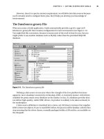
Figure 2-1 shows a modular campus design’s basic structure. Notice how each of the building-block
elements can be confined to a certain area or function. Also notice how each is connected into the
core block.
1-58720-077-5.book Page 37 Tuesday, August 19, 2003 3:16 PM
38 Chapter 2: Modular Network Design
Figure 2-1 Modular Approach to Campus Network Design
The Switch Block
Recall how a campus network is divided into access, distribution, and core layers. The switch block
contains switching devices from the access and distribution layers. All switch blocks then connect
into the core block, providing end-to-end connectivity across the campus.
1-58720-077-5.book Page 38 Tuesday, August 19, 2003 3:16 PM
Modular Network Design 39
Switch blocks contain a balanced mix of Layer 2 and Layer 3 functionality, as might be present in
the access and distribution layers. Layer 2 switches located in wiring closets (access layer) connect
end users to the campus network. With one end user per switch port, each user receives dedicated
bandwidth access.
Upstream, each access layer switch connects to devices in the distribution layer. Here, Layer 2
functionality transports data between all connected access switches at a central connection point.
Layer 3 functionality can also be provided in the form of routing and other networking services
(security, quality of service (QoS), and so on). Therefore, a distribution layer device should be a
multilayer switch. Layer 3 functionality is discussed in more detail in Chapter 13, “Multilayer
Switching.”
The distribution layer also shields the switch block from certain failures or conditions in other parts
of the network. For example, broadcasts will not be propagated from the switch block into the core
and other switch blocks. Therefore, the Spanning Tree Protocol (STP) will be confined to each
switch block, where a virtual LAN (VLAN) is bounded, keeping the spanning tree domain well
defined and controlled.
Access layer switches can support VLANs by assigning individual ports to specific VLAN numbers.
In this way, stations connected to the ports configured for the same VLAN can also share the same
Layer 3 subnet. However, be aware that a single VLAN can support multiple subnets. Because the
switch ports are configured for a VLAN number only (and not a network address), any station
connected to a port can present any subnet address range. The VLAN functions as traditional
network media and allows any network address to connect.
In this network design model, you should not extend VLANs beyond distribution switches. The
distribution layer should always be the boundary of VLANs, subnets, and broadcasts. Although
Layer 2 switches can extend VLANs to other switches and other layers of the hierarchy, this activity
is discouraged. VLAN traffic should not traverse the network core. (Trunking, or the capability to
carry many VLANs over a single connection, is discussed in Chapter 6, “VLANs and Trunks.”)
Sizing a Switch Block
Containing access and distribution layer devices, the switch block is simple in concept. You should
consider several factors, however, to determine an appropriate size for the switch block. The range
of available switch devices makes the switch block size very flexible. At the access layer, switch
selection is usually based on port density or the number of connected users.
1-58720-077-5.book Page 39 Tuesday, August 19, 2003 3:16 PM
40 Chapter 2: Modular Network Design
The distribution layer must be sized according to the number of access layer switches that are
collapsed or brought into a distribution device. Consider the following factors:
■ Traffic types and patterns
■ Amount of Layer 3 switching capacity at the distribution layer
■ Number of users connected to the access layer switches
■ Geographical boundaries of subnets or VLANs
■ Size of Spanning Tree domains
Designing a switch block based solely on the number of users or stations that are contained within
the block is usually inaccurate. Usually, no more than 2000 users should be placed within a single
switch block. Though useful for initially estimating a switch block’s size, this idea doesn’t take into
account the many dynamic processes that occur on a functioning network.
Instead, switch block size should be primarily based on the following:
■ Traffic types and behavior
■ Size and number of common workgroups
Due to the dynamic nature of networks, you can size a switch block too large to handle the load that
is placed upon it. Also, the number of users and applications on a network tends to grow over time.
A provision to break up or downsize a switch block is necessary. Again, base these decisions on the
actual traffic flows and patterns present in the switch block. You can estimate, model, or measure
these parameters with network analysis applications and tools.
Generally, a switch block is too large if the following conditions are observed:
■ The routers (multilayer switches) at the distribution layer become traffic bottlenecks. This
congestion could be due to the volume of interVLAN traffic, intensive CPU processing, or
switching times required by policy or security functions (access lists, queuing, and so on).
■ Broadcast or multicast traffic slows down the switches in the switch block. Broadcast and
multicast traffic must be replicated and forwarded out many ports. This process requires some
overhead in the multilayer switch, which can become too great if significant traffic volumes are
present.
NOTE The actual network analysis process is beyond the scope of this book. Traffic estimation,
modeling, and measurement are complex procedures, each requiring its own dedicated analysis
tool.
1-58720-077-5.book Page 40 Tuesday, August 19, 2003 3:16 PM
Modular Network Design 41
Access switches can have one or more redundant link to distribution layer devices. This situation
provides a fault-tolerant environment, where access layer connectivity is preserved on a secondary
link if the primary link fails. In fact, because Layer 3 devices are used in the distribution layer, traffic
can be load balanced across both redundant links using redundant gateways.
Generally, you should provide two distribution switches in each switch block for redundancy, with
each access layer switch connecting to the two distribution switches. Then, each Layer 3 distribution
switch can load balance traffic over its redundant links into the core layer (also Layer 3 switches)
using routing protocols.
Figure 2-2 shows a typical switch block design. At Layer 3, the two distribution switches can use
one of several redundant gateway protocols to provide an active IP gateway and a standby gateway
at all times. These protocols are discussed in Chapter 14, “Router Redundancy and Load
Balancing.”
Figure 2-2 Typical Switch Block Design
The Core Block
A core block is required to connect two or more switch blocks in a campus network. Because all
traffic passing to and from all switch blocks, server farm blocks, and the enterprise edge block must
cross the core block, the core must be as efficient and resilient as possible. The core is the campus
network’s basic foundation and carries much more traffic than any other block.
A network core can use any technology (frame, cell, or packet) to transport campus data. Many
campus networks use Gigabit and 10 Gigabit Ethernet as a core technology. Ethernet core blocks
are reviewed at length here.
1-58720-077-5.book Page 41 Tuesday, August 19, 2003 3:16 PM
42 Chapter 2: Modular Network Design
Recall that both the distribution and core layers provide Layer 3 functionality. Individual IP subnets
connect all distribution and core switches. At least two subnets should be used to provide resiliency
and load balancing into the core; although, you can use a single VLAN. As VLANs end at the
distribution layer, they are routed into the core.
The core block might consist of a single multilayer switch, taking in the two redundant links from
the distribution layer switches. Due to the importance of the core block in a campus network, you
should implement two or more identical switches in the core to provide redundancy.
The links between layers should also be designed to carry at least the amount of traffic load handled
by the distribution switches. The links between core switches in the same core subnet should be of
sufficient size to carry the aggregate amount of traffic coming into the core switch. Consider the
average link utilization, but allow for future growth. An Ethernet core allows simple and scalable
upgrades of magnitude; consider the progression from Ethernet to Fast Ethernet to Fast
EtherChannel to Gigabit Ethernet to Gigabit EtherChannel, and so on.
Two basic core block designs are presented in the following sections, each designed around a
campus network’s size:
■ Collapsed core
■ Dual core
Collapsed Core
A collapsed core block is one where the hierarchy’s core layer is collapsed into the distribution layer.
Here, both distribution and core functions are provided within the same switch devices. This situa-
tion is usually found in smaller campus networks, where a separate core layer (and additional cost
or performance) is not warranted.
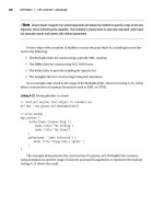
Figure 2-3 shows the basic collapsed core design. Although the distribution and core layer functions
are performed in the same device, keeping these functions distinct and properly designed is impor-
tant. Note also that the collapsed core is not an independent building block but is integrated into the
distribution layer of the individual standalone switch blocks.
In the collapsed core design, each access layer switch has a redundant link to each distribution and
core layer switch. All Layer 3 subnets present in the access layer terminate at the distribution
switches’ Layer 3 ports, as in the basic switch block design. The distribution and core switches
connect to each other by one or more link, completing a path to use during a redundancy failover.
1-58720-077-5.book Page 42 Tuesday, August 19, 2003 3:16 PM
Modular Network Design 43
Figure 2-3 Collapsed Core Block Design
Connectivity between the distribution and core switches is accomplished using Layer 3 links (Layer
3 switch interfaces, with no inherent VLANs). The Layer 3 switches route traffic to and from each
other directly. Figure 2-3 shows the extent of two VLANs. Notice that VLAN A and VLAN B each
extend only from the access layer switches where their respective users are located down to the
distribution layer over the Layer 2 uplinks. The VLANs terminate there because the distribution
layer uses Layer 3 switching. This is good because it limits the broadcast domains, removes the
possibility of Layer 2 bridging loops, and provides fast failover if one uplink fails.
At Layer 3, redundancy is provided through a redundant gateway protocol for IP (covered in Chapter 14).
In some of the protocols, the two distribution switches provide a common default gateway address
to the access layer switches, but only one is active at any time. In other protocols, the two switches
can both be active, load balancing traffic. In the event of a distribution and core switch failure,
connectivity to the core is maintained because the redundant Layer 3 switch is always available.
Dual Core
A dual core connects two or more switch blocks in a redundant fashion. Although the collapsed core
can connect two switch blocks with some redundancy, the core is not scalable when more switch
blocks are added. Figure 2-4 illustrates the dual core. Notice that this core appears as an independent
module and is not merged into any other block or layer.
Access
Layer
Distribution
Layer
Si
Si
VLAN
A
VLAN
B
Layer 2
Links
Si
Si
Switch Block 1
Switch Block 2
Core Links
(Layer 3)
1-58720-077-5.book Page 43 Tuesday, August 19, 2003 3:16 PM
44 Chapter 2: Modular Network Design
Figure 2-4 Dual Network Core Design
In the past, the dual core was usually built with Layer 2 switches to provide the simplest and most
efficient throughput. Layer 3 switching was provided in the distribution layer. Multilayer switches
have now become cost effective and offer high switching performance. Building a dual core with
multilayer switches is both possible and recommended. The dual core uses two identical switches
to provide redundancy. Redundant links connect each switch block’s distribution layer portion to
each of the dual core switches. The two core switches connect by a common link. In a Layer 2 core,
the switches cannot be linked to avoid any bridging loops. A Layer 3 core uses routing rather than
bridging, so bridging loops are not an issue.
In the dual core, each distribution switch has two equal-cost paths to the core, allowing the available
bandwidth of both paths to be used simultaneously. Both paths remain active because the distribu-
tion and core layers use Layer 3 devices that can manage equal-cost paths in routing tables. The rout-
ing protocol in use determines the availability or loss of a neighboring Layer 3 device. If one switch
fails, the routing protocol reroutes traffic using an alternate path through the remaining redundant
switch.
Notice again in Figure 2-4 the extent of the access VLANs. Although Layer 3 devices have been
added into a separate core layer, VLANs A and B still extend only from the Layer 2 access layer
switches down to the distribution layer. Although the distribution layer switches use Layer 3 switch
interfaces to provide Layer 3 functionality to the access layer, these links actually pass traffic only
at Layer 2.
Access
Distribution
Si
Si
VLAN
A
VLAN
B
Layer 2
Links
Si
Si
Switch Block 1
Switch Block 2
Si
Si
Core Block
Layer 3
Links
Layer 3
Links
1-58720-077-5.book Page 44 Tuesday, August 19, 2003 3:16 PM
Modular Network Design 45
Core Size in a Campus Network
The dual core is made up of redundant switches, and is bounded and isolated by Layer 3 devices.
Routing protocols determine paths and maintain the core’s operation. As with any network, you
must pay some attention to the overall design of the routers and routing protocols in the network.
Because routing protocols propagate updates throughout the network, network topologies might be
undergoing change. The network’s size (the number of routers) then affects routing protocol
performance as updates are exchanged and network convergence takes place.
Although the network shown previously in Figure 2-4 might look small with only two switch blocks
of two Layer 3 switches (route processors within the distribution layer switches) each, large campus
networks can have many switch blocks connected into the core block. If you think of each multilayer
switch as a router, you will recall that each route processor must communicate with and keep infor-
mation about each of its directly connected peers. Most routing protocols have practical limits on
the number of peer routers that can be directly connected on a point-to-point or multiaccess link. In
a network with a large number of switch blocks, the number of connected routers can grow quite
large. Should you be concerned about a core switch peering with too many distribution switches?
No, because the actual number of directly connected peers is quite small, regardless of the campus
network size. Access layer VLANs terminate at the distribution layer switches. The only peering
routers at that boundary are pairs of distribution switches, each providing routing redundancy for
each of the access layer VLAN subnets. At the distribution and core boundary, each distribution
switch connects to only two core switches over Layer 3 switch interfaces. Therefore, only pairs of
router peers are formed.
When multilayer switches are used in the distribution and core layers, the routing protocols running
in both layers regard each pair of redundant links between layers as equal-cost paths. Traffic is
routed across both links in a load-sharing fashion, utilizing the bandwidth of both.
One final core layer design point is to scale the core switches to match the incoming load. At
a minimum, each core switch must handle switching each of its incoming distribution links at
100 percent capacity.
Other Building Blocks
Other resources in the campus network can be identified and pulled into the building block model.
For example, a server farm can be made up of servers running applications that are accessed by users
from all across the enterprise. Most likely, those servers need to be scalable for future expansion,
need to be need to be highly accessible, and need to benefit from traffic and security policy control.
To meet these needs, you can group the resources into building blocks that are structured and placed
just like regular switch block modules. These blocks should have a distribution layer of switches and
redundant uplinks directly into the core layer, and should contain enterprise resources.
1-58720-077-5.book Page 45 Tuesday, August 19, 2003 3:16 PM
46 Chapter 2: Modular Network Design
A list of the most common examples follows. Refer back to Figure 2-1 to see how each of these
are grouped and connected into the campus network. Most of these building blocks are present in
medium and large campus networks. Be familiar with the concept of pulling an enterprise function
into its own switch block, as well as the structure of that block.
Server Farm Block
Any server or application accessed by most of the enterprise users usually already belongs to a
server farm. The entire server farm can be identified as its own switch block and given a layer of
access switches uplinked to dual distribution switches (multilayer). Connect these distribution
switches into the core layer with redundant high-speed links.
Individual servers can have single network connections to one of the distribution switches. However,
this presents a single point of failure. If a redundant server is used, it should connect to the alternate
distribution switch. Another more resilient approach is to give each server dual network connec-
tions, one going to each distribution switch. This is known as dual-homing the servers.
Examples of enterprise servers include corporate e-mail, intranet services, Enterprise Resource
Planning (ERP) applications, and mainframe systems. Notice that each of these is an internal
resource that would normally be located inside a firewall or secured perimeter.
Network Management Block
Often, campus networks must be monitored through the use of network management tools so that
performance and fault conditions can be measured and detected. You can group the entire suite of
network management applications into a single network management switch block. This is the
reverse of a server farm block because the network management tools are not enterprise resources
accessed by most of the users. Rather, these tools go out to access other network devices, application
servers, and user activity in all other areas of the campus network.
The network management switch block usually has a distribution layer that connects into the core
switches. Because these tools are used to detect equipment and connectivity failures, availability is
important. Redundant links and redundant switches should be used.
Examples of network management resources in this switch block include the following:
■ Network monitoring applications
■ System logging (syslog) servers
■ Authentication, authorization, and accounting (AAA) servers
■ Policy management applications
■ System administration and remote control services
■ Intrusion detection management applications
1-58720-077-5.book Page 46 Tuesday, August 19, 2003 3:16 PM
Modular Network Design 47
Enterprise Edge Block
At some point, most campus networks must connect to service providers for access to external
resources. This is usually known as the edge of the enterprise or campus network. These resources
are available to the entire campus and should be centrally accessible as an independent switch block
connected to the network core.
Edge services are usually divided into these categories:
■ Internet access—Supports outbound traffic to the Internet, as well as inbound traffic to public
services, such as e-mail and extranet web servers. This connectivity is provided by one or more
Internet service provider (ISP). Network security devices are generally placed here.
■ Remote access and VPN—Supports inbound dialup access for external or roaming users
through the Public Switched Telephone Network (PSTN). If voice traffic is supported over the
campus network, Voice over IP (VoIP) gateways connect to the PSTN here. In addition, virtual
private network (VPN) devices connected to the Internet support secure tunneled connections
to remote locations.
■ E-commerce—Supports all related web, application, and database servers and applications, as
well as firewalls and security devices. This switch block connects to one or more ISPs.
■ WAN access—Supports all traditional WAN connections to remote sites. This can include
Frame Relay, ATM, leased line, ISDN, and so on.
Service Provider Edge Block
Each service provider that connects to an enterprise network must also have a hierarchical network
design of its own. A service provider network meets an enterprise at the service provider edge,
connecting to the enterprise edge block.
Studying a service provider network’s structure isn’t necessary because it should follow the same
design principles presented here. In other words, a service provider is just another enterprise or
campus network itself. Just be familiar with the fact that a campus network has an edge block, where
it connects to the edge of each service provider’s network.
NOTE You can easily gather network management resources into a single switch block to
centralize these functions. Each switch and router in the network must have an IP address
assigned for management purposes. In the past, it was easy to “centralize” all these management
addresses and traffic into a single “management” VLAN, which extended from one end of the
campus to the other.
The end-to-end VLAN concept is now considered a poor practice. VLANs should be isolated,
as described in Chapter 1. Therefore, assigning management addresses to as many VLANs or
subnets as is practical and appropriate for a campus network is now acceptable.
1-58720-077-5.book Page 47 Tuesday, August 19, 2003 3:16 PM
48 Chapter 2: Modular Network Design
Can I Use Layer 2 Distribution Switches?
This chapter covered the best practice design that places Layer 3 switches at both the core and
distribution layers. What would happen if you could not afford Layer 3 switches at the distribution
layer?
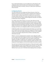
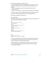
Figure 2-5 shows the dual-core campus network with Layer 2 distribution switches. Notice how
each access VLAN extends not only throughout the switch block but also into the core. This is
because the VLAN terminates at a Layer 3 boundary present only in the core. As an example, VLAN
A’s propagation is shaded in the figure.
Figure 2-5 Design Using Layer 2 Distribution Switches
Here are some implications with this design:
■ Redundant Layer 3 gateways can still be used in the core.
■ Each VLAN propagates across the redundant trunk links from the access to the core layers.
Because of this, Layer 2 bridging loops form.
Access
Distribution
VLAN
A
VLAN
B
Layer 2
Links
Switch Block 1
Switch Block 2
Si
Si
Core Block
Layer 3
Links
Layer 3
Links
1-58720-077-5.book Page 48 Tuesday, August 19, 2003 3:16 PM
Can I Use Layer 2 Distribution Switches? 49
■ The STP must run in all layers to prevent Layer 2 loops. This causes traffic on some links to be
blocked. As a result, only one of every two access layer switch uplinks can be used at any time.
■ When Layer 2 uplinks go down, the STP can take several seconds to unblock redundant links,
causing downtime.
■ Access VLANs can propagate from one end of the campus to the other, if necessary.
■ Broadcast traffic on any access layer VLAN also reaches into the core layer. Bandwidth on
uplinks and within the core can be unnecessarily wasted.
1-58720-077-5.book Page 49 Tuesday, August 19, 2003 3:16 PM
50 Chapter 2: Modular Network Design
Foundation Summary
The Foundation Summary is a collection of tables, figures, lists, and other information that provides
a convenient review of many key concepts in this chapter. If you are already comfortable with the
topics in this chapter, this summary might help you recall a few details. If you just read this chapter,
this review should help solidify some key facts. If you are doing your final preparation before the
exam, the following information is a convenient way to review the day before the exam.
A campus network can be logically divided into these building blocks:
■ Switch block—A group of access layer switches together with their distribution switches.
■ Core block—The campus network’s backbone.
■ Server Farm block—A group of enterprise servers along with their access and distribution
layer switches.
■ Management block—A group of network management resources along with their access and
distribution switches.
■ Enterprise Edge block—A collection of services related to external network access, along
with their access and distribution switches.
■ Service Provider Edge block—The external network services contracted or used by the
enterprise network; these are the services with which the enterprise edge block interfaces.
Other than the core block, each switch block should have the following characteristics:
■ Switches that form an access layer
■ Dual distribution switches
■ Redundant connections into the access and core layers
The most important factors to consider when choosing a switch block’s size are as follows:
■ The number of users connected to the access layer switches
■ The extent of the access VLAN or subnet
■ Multilayer switching capacity of the distribution switches in the switch block
■ The types, patterns, and volume of traffic passing through the switch block
1-58720-077-5.book Page 50 Tuesday, August 19, 2003 3:16 PM
Foundation Summary 51
The core layer in a campus network can be designed as follows:
■ Collapsed core—The distribution and core layer switches are combined. This is usually
acceptable in a small to medium-sized network.
■ Dual core—The distribution and core layers are separate; the core layer consists of dual or
redundant multilayer switches.
1-58720-077-5.book Page 51 Tuesday, August 19, 2003 3:16 PM
52 Chapter 2: Modular Network Design
Q&A
The questions and scenarios in this book are more difficult than what you should experience on the
actual exam. The questions do not attempt to cover more breadth or depth than the exam; however,
they are designed to make sure that you know the answer. Rather than allowing you to derive the
answers from clues hidden inside the questions themselves, the questions challenge your
understanding and recall of the subject. Hopefully, these questions will help limit the number of
exam questions on which you narrow your choices to two options and then guess.
You can find the answers to these questions in Appendix A.
1. Where is the most appropriate place to connect a block of enterprise (internal) servers? Why?
2. How can you provide redundancy at the switch and core block layers? (Consider physical
means, as well as functional methods using protocols, algorithms, and so on.)
3. What factors should you consider when sizing a switch block?
4. What are the signs of an oversized switch block?
5. What are the attributes and issues of having a collapsed core block?
6. How many switches are sufficient in a core block design?
7. What building blocks are used to build a scalable campus network?
8. What are two types of core, or backbone, designs?
9. Why should links and services provided to remote sites be grouped in a distinct building block?
10. Why should network management applications and servers be placed in a distinct building
block?
1-58720-077-5.book Page 52 Tuesday, August 19, 2003 3:16 PM
1-58720-077-5.book Page 53 Tuesday, August 19, 2003 3:16 PM
PART II: Building a Campus
Network
Chapter 3 Switch Operation
Chapter 4 Switch Configuration
Chapter 5 Switch Port Configuration
Chapter 6 VLANs and Trunks
Chapter 7 VLAN Trunking Protocol (VTP)
Chapter 8 Aggregating Switch Links
Chapter 9 Traditional Spanning Tree Protocol
Chapter 10 Spanning Tree Configuration
Chapter 11 Protecting the Spanning Tree Protocol Topology
Chapter 12 Advanced Spanning Tree Protocol
This part of the book covers the following BCMSN exam topics:
■ Describe the physical, data-link, and network layer technologies used in a switched
network, and identify when to use each.
■ Explain the function of the Switching Database Manager within a Catalyst switch.
■ Describe the features and operation of VLANs on a switched network.
1-58720-077-5.book Page 54 Tuesday, August 19, 2003 3:16 PM