ccnp 642 811 bcmsn exam certification guide second edition phần 7 pdf
Bạn đang xem bản rút gọn của tài liệu. Xem và tải ngay bản đầy đủ của tài liệu tại đây (2.36 MB, 63 trang )
Server Load Balancing (SLB) 345
Step 2 Choose a load-balancing method.
Switch(config-slb-sfarm)# predictor {roundrobin | leastconns}
Either weighted round-robin (the default) or weighted least connections can
be used.
Step 3 Identify the real servers in the server farm:
Switch(config-slb-sfarm)# real
ip-address
The server’s actual IP address is given.
Step 4 Assign a weight for the relative server capacity:
Switch(config-slb-real)# weight
weighting-value
The weighting value (1 to 255, default 8) indicates the server’s capacity to
accept new connections, relative to the other real servers in the server farm.
Step 5 Put the real server into service:
Switch(config-slb-real)# inservice
By default, SLB cannot use a real server until it is manually put into service.
Later, the real server can be taken out of service for maintenance with the no
inservice command. This removes it from use in the SLB server farm until it is
returned to service again. (To take a real server out of service, first get into the
real server configuration mode by using the commands from Steps 1 and 3.)
Virtual Servers
Configure each virtual server by the following series of steps:
Step 1 Name the virtual server:
Switch(config)# ip slb vserver
virtual-server-name
The virtual server is given a descriptive name, up to 15 characters.
Step 2 Assign the virtual server to a server farm:
Switch(config-slb-vserver)# serverfarm
serverfarm-name
SLB uses the virtual server as the front end for the server farm named. This
server farm must already be configured, populated with one or more real
servers.
Step 3 Assign an IP address to the virtual server:
Switch(config-slb-vserver)# virtual
ip-address
Step 4 Control access to the virtual server:
Switch(config-slb-vserver)# client
ip-address inverse-mask
1-58720-077-5.book Page 345 Tuesday, August 19, 2003 3:16 PM
346 Chapter 14: Router Redundancy and Load Balancing
By default, any client from any IP address can make connections to the
virtual server. To limit the access, define only the IP subnet or address range
(with subnet mask) that is allowed access. The inverse-mask here resembles
that of an access list, where a 1-bit ignores and a 0-bit matches.
Step 5 Put the virtual server into service:
Switch(config-slb-vserver)# inservice
By default, SLB does not allow connections to be made to a virtual server
until it is put into service. If a virtual server needs to be temporarily disabled
for some reason, use the no inservice command.
Verifying Redundancy and Load Balancing
To verify the operation of the features discussed in this chapter, you can use the commands listed in
Table 14-3. In particular, look for the active router, standby or backup routers, and load-balancing
methods in use.
Table 14-3 Redundancy and Load Balancing Verification Commands
Task Command Syntax
HSRP and VRRP
Show HSRP status. show standby brief
Show HSRP on an interface. show standby type mod/num
Show VRRP status. show vrrp brief all
Show VRRP on an interface. show vrrp interface type mod/num
GLBP
Show status of a GLBP group. show glbp group
SLB
Show server farms. show ip slb serverfarms
Show real servers. show ip slb reals
Show virtual servers. show ip slb vserver
Show current SLB connections. show ip slb conns
1-58720-077-5.book Page 346 Tuesday, August 19, 2003 3:16 PM
Foundation Summary 347
Foundation Summary
The Foundation Summary is a collection of information that provides a convenient review of many
key concepts in this chapter. If you are already comfortable with the topics in this chapter, this
summary can help you recall a few details. If you just read this chapter, this review should help
solidify some key facts. If you are doing your final preparation before the exam, this information is
a convenient way to review the day before the exam.
Table 14-4 A Comparison of Router Redundancy Protocols
HSRP VRRP GLBP
Standard? no; Cisco-proprietary,
RFC 2281
yes; RFC 2338 no; Cisco-proprietary
Router roles Active router, standby
router
Master router, backup
router
AVG, AVF
Load balancing Only through multiple
HSRP groups, different
client gateways
Only through multiple
VRRP groups, different
client gateways
Inherent with one
GLBP group; all clients
use same gateway;
several methods
available
Interface tracking yes no yes
Virtual router MAC
address
0000.0c07.acxx 0000.5e00.01xx assigned by AVG
Table 14-5 HSRP Configuration Commands
Task Command Syntax
Set the HSRP priority. standby group priority priority
Set the HSRP timers. standby group timers hello holdtime
Allow router preemption. standby group preempt [delay seconds]
Use group authentication. standby group authentication string
Adjust priority by tracking an interface. standby group track type mod/num decrementvalue
Assign the virtual router address. standby group ip ip-address [secondary]
1-58720-077-5.book Page 347 Tuesday, August 19, 2003 3:16 PM
348 Chapter 14: Router Redundancy and Load Balancing
Table 14-6 VRRP Configuration Commands
Task Command Syntax
Assign a VRRP router priority (default 100). vrrp group priority level
Alter the advertisement timer (default 1 second). vrrp group timers advertise [msec] interval
Learn the advertisement interval from the master router. vrrp group timers learn
Disable preempting (default is to preempt). no vrrp group preempt
Change the preempt delay (default 0 seconds). vrrp group preempt [delay seconds]
Use authentication for advertisements. vrrp group authentication string
Assign a virtual IP address. vrrp group ip ip-address [secondary]
Table 14-7 GLBP Configuration Commands
Task Command Syntax
Assign a GLBP priority. glbp group priority level
Allow GLBP preemption. glbp group preempt [delay minimum seconds]
Define an object to be
tracked.
track object-number interface type mod/num {line-protocol | ip routing}
Define the weighting
thresholds.
glbp group weighting maximum [lower lower] [upper upper]
Track an object. glbp group weighting track object-number [decrement value]
Choose the load-balancing
method.
glbp group load-balancing [round-robin | weighted | host-dependent]
Assign a virtual router
address.
glbp group ip [ip-address [secondary]]
1-58720-077-5.book Page 348 Tuesday, August 19, 2003 3:16 PM
Foundation Summary 349
Table 14-8 SLB Configuration Commands
Task Command Syntax
Name a server farm. ip slb serverfarm serverfarm-name
Choose a load-balancing method. predictor {roundrobin | leastconns}
Identify a real server. real ip-address
Assign a relative weight to the real server. weight weighting-value
Enable the server for use. inservice
Name the virtual server. ip slb vserver virtual-server-name
Link the virtual server to a server farm. serverfarm serverfarm-name
Limit access to the virtual server. client ip-address network-mask
Define the virtual server IP address. virtual ip-address
Enable the virtual server for use. inservice
1-58720-077-5.book Page 349 Tuesday, August 19, 2003 3:16 PM
350 Chapter 14: Router Redundancy and Load Balancing
Q&A
The questions and scenarios in this book are more difficult than what you should experience on the
actual exam. The questions do not attempt to cover more breadth or depth than the exam; however,
they are designed to make sure that you know the answer. Rather than allowing you to derive the
answers from clues hidden inside the questions themselves, the questions challenge your under-
standing and recall of the subject. Hopefully, these questions will help limit the number of exam
questions on which you narrow your choices to two options and then guess.
You can find the answers to these questions in Appendix A.
1. A multilayer switch has been configured with the command standby 5 priority 120. What
router redundancy protocol is being used?
2. What feature can you use to prevent other routers from accidentally participating in an HSRP
group?
3. What command can configure an HSRP group to use a virtual router address of
192.168.222.100?
4. The show standby vlan 271 command produces the following output:
Vlan271 - Group 1
Local state is Active, priority 210, may preempt
Hellotime 3 holdtime 40 configured hellotime 3 sec holdtime 40 sec
Next hello sent in 00:00:00.594
Virtual IP address is 192.168.111.1 configured
Secondary virtual IP address 10.1.111.1
Secondary virtual IP address 172.21.111.1
Active router is local
Standby router is unknown expires in 00:00:37
Standby virtual mac address is 0000.0c07.ac01
2 state changes, last state change 5d17h
If the local router fails, which router takes over the active role for the virtual router address
192.168.111.1?
5. What is meant by preempting in HSRP?
6. What protocols discussed in this chapter support interface tracking?
1-58720-077-5.book Page 350 Tuesday, August 19, 2003 3:16 PM
Q&A 351
7.
The show standby brief command has been used to check the status of all HSRP groups on the
local router. The output from this command is as follows:
Switch# ss
ss
hh
hh
oo
oo
ww
ww
ss
ss
tt
tt
aa
aa
nn
nn
dd
dd
bb
bb
yy
yy
bb
bb
rr
rr
ii
ii
ee
ee
ff
ff
P indicates configured to preempt.
|
Interface Grp Prio P State Active addr Standby addr Group addr
Vl100 1 210 P Active local 192.168.75.2 192.168.75.1
Vl101 1 210 P Active local 192.168.107.2 192.168.107.1
Vl102 1 210 P Active local 192.168.71.2 192.168.71.1
Each interface is shown to have Group 1. Is this a problem?
8. How many HSRP groups are needed to load balance traffic over two routers?
9. What load-balancing methods can GLBP use?
10. What command can you use to see the status of the active and standby routers on the VLAN
171 interface?
11. How many GLBP groups are needed to load balance traffic over four routers?
12. When should you use SLB?
13. What command defines and names an SLB server farm?
14. A virtual server has just been defined with the following commands:
ii
ii
pp
pp
ss
ss
ll
ll
bb
bb
vv
vv
ss
ss
ee
ee
rr
rr
vv
vv
ee
ee
rr
rr
CC
CC
II
II
SS
SS
CC
CC
OO
OO
ss
ss
ee
ee
rr
rr
vv
vv
ee
ee
rr
rr
ff
ff
aa
aa
rr
rr
mm
mm
CC
CC
II
II
SS
SS
CC
CC
OO
OO
FF
FF
AA
AA
RR
RR
MM
MM
vv
vv
ii
ii
rr
rr
tt
tt
uu
uu
aa
aa
ll
ll
11
11
99
99
22
22
11
11
66
66
88
88
11
11
99
99
99
99
11
11
77
77
Can the virtual server be used immediately? If not, what additional command is needed?
1-58720-077-5.book Page 351 Tuesday, August 19, 2003 3:16 PM
This chapter covers the
following topics that you
need to master for the CCNP
BCMSN exam:
■ Multicast Overview—This section dis-
cusses multicast addressing and general
multicast traffic forwarding.
■ Routing Multicast Traffic—This section
covers the protocols used by Layer 3 devices
to maintain multicast groups and their
members, and to constrain multicast
forwarding.
■ Switching Multicast Traffic—This section
explains techniques that you can use to intel-
ligently forward multicast traffic at Layer 2.
■ Verifying Multicast—This section provides
a brief summary of the commands that can
verify the configuration and operation of mul-
ticast routing and switching.
1-58720-077-5.book Page 352 Tuesday, August 19, 2003 3:16 PM
C H A P T E R
15
Multicast
Multicast traffic is typically sent by one source and received by a group of recipients, spread
throughout a network and changing over time. Examples of multicast traffic include video
streams for instruction or entertainment, certain audio conference calls, and one-to-many PC
file imaging applications.
Because not everyone on a network wants to receive the traffic from a multicast source, switches
and routers must have some means to forward traffic to exactly the destinations that want to
receive it. This chapter covers IP multicast and the various protocols used to forward multicast
packets.
“Do I Know This Already?” Quiz
The purpose of the “Do I Know This Already?” quiz is to help you decide what parts of this
chapter to use. If you already intend to read the entire chapter, you do not necessarily need to
answer these questions now.
The quiz, derived from the major sections in the “Foundation Topics” portion of the chapter,
helps you determine how to spend your limited study time.
Table 15-1 outlines the major topics discussed in this chapter and the “Do I Know This
Already?” quiz questions that correspond to those topics.
Table 15-1 “Do I Know This Already?” Foundation Topics Section-to-Question Mapping
Foundation Topics Section Questions Covered in This Section
Multicast Overview 1–7
Routing Multicast Traffic 8–11
Switching Multicast Traffic 12
1-58720-077-5.book Page 353 Tuesday, August 19, 2003 3:16 PM
354 Chapter 15: Multicast
1.
How many sources are typically present in a multicast group?
a. 1
b. 2
c. As many as are registered with the router
d. Cannot be determined
2. Which one of the following is a multicast address?
a. 128.224.1.1
b. 172.17.224.1
c. 225.17.1.1
d. 242.17.1.1
3. 224.1.2.3 corresponds to which of the following MAC addresses?
a. 0102.0300.0000
b. 0100.5e01.0203
c. e000.0001.0203
d. 1000.5e01.0203
4. How many unique multicast IP addresses can correspond to one multicast MAC address?
a. 1
b. 2
c. 8
d. 32
CAUTION The goal of self-assessment is to gauge your mastery of the topics in this chapter. If
you do not know the answer to a question or are only partially sure of the answer, you should mark
this question wrong. Giving yourself credit for an answer you correctly guess skews your self-
assessment results and might give you a false sense of security.
1-58720-077-5.book Page 354 Tuesday, August 19, 2003 3:16 PM
“Do I Know This Already?” Quiz 355
5.
Which of the following is the test that is performed before a multicast packet can be forwarded?
a. Shortest Path First
b. Cyclic Redundancy Check
c. Reverse Path Forwarding
d. Multicast Route Verification
6. Which protocol registers hosts for multicast group membership?
a. CGMP
b. IGRP
c. IGMP
d. PIM
7. A host sends Internet Group Management Protocol (IGMP) packets to which of the following?
a. The local switch
b. The local router
c. The multicast source
d. The root of the multicast tree
8. If a multicast group has recipients on every subnet, which of the PIM modes should be used?
a. Dense mode
b. Sparse mode
c. Sparse-compress mode
d. Flood mode
9. Which type of tree structure is built for sparse mode multicast routing?
a. Spanning Tree
b. Shared Tree
c. Sparse Tree
d. Simple Tree
1-58720-077-5.book Page 355 Tuesday, August 19, 2003 3:16 PM
356 Chapter 15: Multicast
10.
What router maintains the RP-to-group correlation for Auto-RP in PIMv1?
a. RP agent
b. PIM root
c. Mapping agent
d. RP discovery server
11. What router advertises candidate RP routers in PIMv2?
a. Auto-RP
b. Mapping agent
c. Bootstrap router
d. PIM root
12. Which of the following methods requires a router to assist a Layer 2 switch in constraining
multicast traffic?
a. PIM
b. IGMP
c. CGMP
d. IGMP snooping
You can find the answers to the “Do I Know This Already?” quiz in Appendix A, “Answers to
Chapter ‘Do I Know This Already?’ Quizzes and Q&A Sections.” The suggested choices for your
next step are as follows:
■ 10 or less overall score—Read the entire chapter. This includes the “Foundation Topics,”
“Foundation Summary,” and “Q&A” sections.
■ 11 or 12 overall score—If you want more review on these topics, skip to the “Foundation
Summary” section and then go to the “Q&A” section at the end of the chapter. Otherwise, move
to Chapter 16, “Quality of Service Overview.”
1-58720-077-5.book Page 356 Tuesday, August 19, 2003 3:16 PM
Multicast Overview 357
Foundation Topics
Multicast Overview
In a network, three basic types of IP traffic traverse the routers and switches:
■ Unicast—Packets that are sent from one source host address to a single destination host
address. A router or Layer 3 switch forwards them by finding the destination IP address in
its routing table. A Layer 2 switch relies only on the destination’s MAC address.
■ Broadcast—Packets that are sent from one source host address to a broadcast destination
address. The destination can be all-hosts (255.255.255.255), a directed broadcast to a subnet
(that is, 192.168.10.255), or some portion of a subnet. A router or Layer 3 switch will not
forward these by default, unless some method of relaying has been configured. A Layer 2
switch floods the packet out all ports on the destination VLAN.
■ Multicast—Packets that are sent from one source host address to a special group-based
destination address. The destination represents only the hosts that are interested in receiving the
packets, and no others. A router or Layer 3 switch does not forward these packets by default,
unless some form of multicast routing is enabled. A Layer 2 switch cannot learn the location of
the destination multicast address, the packets are flooded to all ports on the destination VLAN
by default.
Two extremes are covered here—a unicast, which travels from host to host, and a broadcast, which
travels from one host to everyone on a segment. Multicast falls somewhere in the middle, where the
intention is to send packets from one host to only the users that want to receive them, namely those
in the designated multicast group. Ideally, the recipients of multicast packets could be located
anywhere, not just on the local segment.
Multicast traffic is generally unidirectional. Because many hosts are receiving the same data, it
makes little sense to allow one of the hosts to send packets back toward the source over the multicast
mechanism. Instead, a receiving host can send return traffic to the source as a unicast. Multicast
traffic is also sent in a best-effort connectionless format. UDP (connectionless) is commonly used,
whereas TCP (connection-oriented) is not.
Hosts that want to receive data from a multicast source can join or leave a multicast group dynami-
cally. In addition, a host can decide to become a member of more than one multicast group at any
time. The principle network task is then to figure out how to deliver multicast traffic to the group
members without disturbing other uninterested hosts.
1-58720-077-5.book Page 357 Tuesday, August 19, 2003 3:16 PM
358 Chapter 15: Multicast
Multicast Addressing
Routers and switches must have a way to distinguish multicast traffic from unicasts or broadcasts.
This is done through IP addressing, by reserving the Class D IP address range, 224.0.0.0 through
239.255.255.255, strictly for multicasting. Network devices can quickly pick out multicast IP
addresses by looking at the four most-significant bits, which are always 1110.
How does a router or switch relate a multicast IP address with a MAC address? There is no Address
Resolution Protocol (ARP) equivalent for multicast address mapping. Instead, a reserved Organiza-
tionally Unique Identifier (OUI) value is set aside so that multicast MAC addresses always begin
with 0100.5e (plus the next lower bit, which is zero). The lower 28 bits of the multicast IP address
must also be mapped into the lower 23 bits of the MAC address by a simple algorithm.
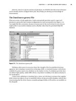
Figure 15-1 shows the address mapping concept. Only the lower 23 bits of the address are copied
from IP to MAC (or vice versa). The high-order prefix of both IP and MAC addresses are fixed,
predictable values.
Figure 15-1 Multicast IP-to-MAC Address Translation
Notice, however, that 5 bits of the IP address are not transferred into the MAC address. This gives
the possibility that the multicast MAC addresses are not entirely unique—there are 32 different
multicast IP addresses that could all correspond to a single multicast MAC address.
Because of this ambiguity, a multicast host has a small problem when it receives an Ethernet frame
destined for a multicast MAC address. That one MAC address could actually correspond to 32
different multicast IP addresses. Therefore, the host must receive and examine every frame that has
the MAC address it is interested in—regardless to which of the 32 IP addresses the frame was
originally destined. The host must examine the IP header inside each frame to verify that the more
specific IP multicast address is a desired multicast group.
1-58720-077-5.book Page 358 Tuesday, August 19, 2003 3:16 PM
Routing Multicast Traffic 359
Some of the IP multicast address space has been reserved for a particular use:
■ Complete multicast space: 224.0.0.0 through 239.255.255.255—The entire range of IP
addresses that can be used for multicast purposes.
■ Link-local addresses (224.0.0.0 through 224.0.0.255)—Used by network protocols only on
the local network segment. Routers do not forward these packets.
This space includes the all-hosts address 224.0.0.1, all-routers 224.0.0.2, OSPF-routers
224.0.0.5, and so on. These are also known as fixed-group addresses because they are well-
known and predefined.
■ Administratively scoped addresses (239.0.0.0 through 239.255.255.255)—Used in private
multicast domains, much like the private IP address ranges from RFC 1918. These addresses
are not routed between domains, so they can be reused.
■ Globally scoped addresses (224.0.1.0 through 238.255.255.255)—Used by any entity; these
addresses can be routed across an organization or the Internet, so they must be unique and
globally significant. (Think of this range as neither local nor private; it is the rest of the multicast
range.)
Routing Multicast Traffic
IP multicast traffic must be routed, just like any other Layer 3 packets. The difference is in knowing
where to forward the packets. Unicast IP packets have only one destination interface (even if mul-
tiple paths exist), whereas multicast IP packets can have many destination interfaces, depending
upon where the recipients are located.
Several multicast routing protocols are available. This text focuses only on Protocol Independent
Multicast (PIM), as does the BCMSN course. Multicast routing as a whole is better covered in
routing courses and textbooks. This section provides an overview of the PIM operation to provide
a good understanding of the routing concepts. This is a necessary foundation for understanding
multicast switching (Layer 2).
Regardless of the multicast routing protocol used, you must first enable multicast routing on the
router or switch with the following global configuration command:
Switch(config)# ii
ii
pp
pp
mm
mm
uu
uu
ll
ll
tt
tt
ii
ii
cc
cc
aa
aa
ss
ss
tt
tt
rr
rr
oo
oo
uu
uu
tt
tt
ii
ii
nn
nn
gg
gg
Multicast Trees
The routers (or multilayer switches) in a network must determine a forwarding path to get multicast
packets from the source (sender) to each of the recipients. Think of the network as a tree structure.
At the root of the tree is the source, blindly sending IP packets to a specific multicast address. Each
router along the way sits at a branch or fork in the tree. If a router knows where all of the multicast
1-58720-077-5.book Page 359 Tuesday, August 19, 2003 3:16 PM
360 Chapter 15: Multicast
group recipients are located, it also knows which branches of the tree to replicate the multicast
packets onto. Some routers have no downstream recipients, so they do not forward the multicast
traffic. Other routers have many downstream recipients.
This tree structure is somewhat similar to a Spanning Tree topology, as it has a root at one end and
leaf nodes (the recipients) at the other end. The tree is also loop-free so that none of the multicast
traffic gets fed back into the tree.
Reverse Path Forwarding
Routers usually have one test to perform on every multicast packet they receive. Reverse Path
Forwarding (RPF) is a means to make sure packets are not being injected back into the tree at an
unexpected location.
As a packet is received on a router interface, the source IP address is inspected. The idea is to verify
that the packet arrived on the same interface where the source can be found. If this is true, the packet
is actually proceeding out the branches of the tree, away from the source. If it is not true, someone
else has injected the packet on an unexpected interface, headed back down the branches of the tree
toward the source.
To perform the RPF test, the PIM router looks up the source address in its unicast routing table. If
the next-hop interface used to reach the source address also matches the interface where the packet
was received, the packet can be forwarded or replicated toward the multicast recipients. If not, the
packet is quietly discarded.
IGMP
How does a router know of the recipients in a multicast group, much less of their locations? To
receive multicast traffic from a source, both the source and every recipient must first join a common
multicast group. This group is also known by its multicast IP address.
A host can join a multicast group by sending a request to its local router. This is done through the
Internet Group Management Protocol (IGMP). IGMPv1 is defined in RFC 1112, and its successor,
IGMPv2, in RFC 2236. When several hosts join a group by contacting their local routers, it is the
multicast routing protocol (such as PIM) that “connects the dots” and forms the multicast tree
between routers.
IGMPv1
To join a multicast group, a host can dynamically send a Membership Report IGMP message to its
local router. This message tells the router what multicast address (group) the host is joining. The
multicast address is used as the destination IP address, as well as the group address listed in the
message.
1-58720-077-5.book Page 360 Tuesday, August 19, 2003 3:16 PM
Routing Multicast Traffic 361
Every 60 seconds, one router on each network segment queries all hosts to see if they are interested
in receiving multicast traffic. This router is known as the IGMPv1 Querier and functions simply to
invite hosts to join a group. Queries are sent to the 224.0.0.1 all-hosts multicast address for quick
distribution. If a host is interested in joining a group, or if it wants to continue receiving a group that
it has already joined, it must respond with a membership report.
Hosts can join multicast groups at any time. However, IGMPv1 does not have a mechanism to allow
a host to leave a group if it is no longer interested in the group’s content. Instead, routers age a
multicast group out of an interface (network segment) if no membership reports are received for
three consecutive query intervals. This means that, by default, multicast traffic is still sent onto a
segment for up to 3 minutes after all the group members have stopped listening.
Notice that a router does not need to keep a complete host membership list for each multicast group
that is active. Rather, it needs to only record which multicast groups are active on which interfaces.
IGMPv2
IGMP version 2 introduced several differences from the first version. Queries can be sent as General
Queries to the all-hosts address (as in IGMPv1), as well as Group-Specific Queries, sent only to
members of a specific group.
In addition, hosts are allowed to leave a group dynamically. When a host decides to leave a group it
has joined, it sends a Leave Group message to the all-routers address (224.0.0.2). All routers on the
local segment take note, and the Querier router decides to investigate further. It responds with a
Group-Specific Query message, asking if anyone is still interested in receiving traffic for that group.
Any other hosts must reply with a Membership Report. Otherwise, the Querier safely assumes that
there is no need to continue forwarding the group traffic on that segment.
PIM
Protocol Independent Multicast (PIM) is a routing protocol that can be used for forwarding multi-
cast traffic. PIM operates independent of any particular IP routing protocol. Therefore, PIM makes
use of the IP unicast routing table and does not keep a separate multicast routing table. (The unicast
routing table is itself routing protocol-independent because one or more routing protocols can be
used to populate a single table.)
NOTE If any IGMPv1 routers are on a segment, all routers on the segment must run IGMPv1.
Otherwise, the IGMPv1 routers cannot understand the IGMPv2 messages.
On interfaces where PIM is configured, IGMPv2 is enabled by default.
1-58720-077-5.book Page 361 Tuesday, August 19, 2003 3:16 PM
362 Chapter 15: Multicast
PIM can operate in two modes, depending on the density of the recipients in a multicast group. Cisco
has developed a third hybrid mode, as well. The PIM modes are as follows:
■ PIM Dense Mode
■ PIM Sparse Mode
■ PIM Sparse-Dense Mode
In addition, two versions of the PIM protocol can be used in a network: PIM version 1 and PIM
version 2.
PIM Dense Mode
PIM routers can be configured for Dense Mode (also called PIM-DM) if it is safe to assume that a
multicast group’s recipients are located on every subnet. The multicast traffic’s source becomes the
root of the tree, and the multicast tree is known from the source to each of the recipients. This is also
termed (S,G) multicast traffic, where the path between the source and group members is unique and
well-defined.
The multicast tree is built by first allowing a flood of traffic from the source to every dense mode
router in the network. The tree is grown from the top down. For a brief time, unnecessary traffic is
allowed, much as a broadcast would do. However, as each router receives traffic for the group, it
must decide whether it has active recipients wanting to receive the data. If so, the router can remain
quiet and let the flow continue. If no hosts have registered for the multicast group with the router
(via IGMP), the router sends a Prune message to its neighbor toward the source. That branch of the
tree is then pruned off so that the unnecessary traffic does not continue.
Figure 15-2 shows dense mode’s flood-then-prune operation. The tree is built by a wave of join
requests moving through all dense mode multilayer switches. Then, the switches that have no
interested hosts request to be pruned from the tree. The resulting tree and multicast flow is shown
in Figure 15-4 in the section on PIM Sparse Mode.
PIM-DM routers become aware of their neighbors by exchanging hello messages. This neighbor
information is used first to build the tree to all neighbors, and then to prune branches away.
If a multicast flow has begun, and the tree has been built and then pruned, the tree exists only where
active group members are located. If a new host registers for the group, the branch of the network
where it is located can be added or grafted back onto the tree.
To configure PIM Dense Mode on an interface, use the following interface configuration command:
Switch(config-if)# ii
ii
pp
pp
pp
pp
ii
ii
mm
mm
dd
dd
ee
ee
nn
nn
ss
ss
ee
ee
mm
mm
oo
oo
dd
dd
ee
ee
1-58720-077-5.book Page 362 Tuesday, August 19, 2003 3:16 PM
Routing Multicast Traffic 363
Figure 15-2 PIM Dense Mode Constructs a Multicast Tree
PIM Sparse Mode
PIM Sparse Mode (also called PIM-SM) takes a different approach—the multicast tree isn’t
extended to a router unless a host there has already joined the group. The multicast tree is built by
beginning with the group members at the end leaf nodes and extending back toward a central root
point. The tree is built from the bottom up.
Sparse Mode also works on the idea of a shared tree structure, where the root is not necessarily the
multicast source. Instead, the root is a PIM-SM router that is centrally located in the network. This
root router is called the Rendezvous Point (RP).
The tree from the RP to the group members is actually a subset of the tree that could be drawn from
the source to the group members. If a multicast source anywhere in the network can register for
group membership with the RP, the tree can be completed. Because of this, the Sparse Mode tree is
called a shared tree. Sparse Mode multicast flows are described as (*,G) because the tree allows any
source to send to a group.
1-58720-077-5.book Page 363 Tuesday, August 19, 2003 3:16 PM
364 Chapter 15: Multicast
As a recipient joins a multicast group (IGMP), the local router forwards the Membership Report
toward the RP at the root of the tree. Each router along the way adds that branch to the shared tree.
Pruning is performed only when a group member is removed from the group. This process is shown
in Figure 15-3. Notice that it consists of only one step—only routers with active group members join
the tree. The routers that did not join the group are not pruned because they never became a part of
the tree.
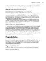
Figure 15-4 illustrates the resulting tree structures for both PIM Dense and PIM Sparse Modes,
along with the multicast data flow. Notice that both PIM modes have constructed identical tree
structures, yielding the same multicast traffic flow patterns.
Figure 15-3 PIM Sparse Mode Constructs a Multicast Tree
To configure PIM Sparse Mode on an interface, use the following interface configuration command:
Switch(config-if)# ii
ii
pp
pp
pp
pp
ii
ii
mm
mm
ss
ss
pp
pp
aa
aa
rr
rr
ss
ss
ee
ee
mm
mm
oo
oo
dd
dd
ee
ee
1-58720-077-5.book Page 364 Tuesday, August 19, 2003 3:16 PM
Routing Multicast Traffic 365
Figure 15-4 Identical Results from PIM Dense and Sparse Modes
PIM Sparse-Dense Mode
PIM has the potential to support both Dense and Sparse Modes, because they exist on different
multicast groups in a network. Cisco offers the hybrid Sparse-Dense Mode, allowing a PIM router
to use Sparse or Dense Mode on a per-group basis. If a group has an RP defined, Sparse Mode is
used; otherwise, Dense Mode is used.
To configure PIM Sparse-Dense Mode on an interface, use the following interface configuration
command:
Switch(config-if)# ii
ii
pp
pp
pp
pp
ii
ii
mm
mm
ss
ss
pp
pp
aa
aa
rr
rr
ss
ss
ee
ee
dd
dd
ee
ee
nn
nn
ss
ss
ee
ee
mm
mm
oo
oo
dd
dd
ee
ee
PIM Version 1
For routers using the first version of PIM, RPs can be configured manually or by the more dynamic
auto-RP process. To manually identify an RP, use the following global configuration command:
Switch(config)# ii
ii
pp
pp
pp
pp
ii
ii
mm
mm
rr
rr
pp
pp
aa
aa
dd
dd
dd
dd
rr
rr
ee
ee
ss
ss
ss
ss
ip-address
[
access-list-number
] [oo
oo
vv
vv
ee
ee
rr
rr
rr
rr
ii
ii
dd
dd
ee
ee
]
Multicast Server
Recipient A
Recipient B
PIM Dense Mode Tree
Multicast Server
Recipient A
Recipient B
PIM Sparse Mode Tree
Root
RP
1-58720-077-5.book Page 365 Tuesday, August 19, 2003 3:16 PM
366 Chapter 15: Multicast
You can limit the range of multicast groups supported by the RP by using an access list. The
override keyword causes this RP to be preferred over any that is automatically determined. The
RP must be defined on every router in the PIM domain, including the RP itself.
Cisco also provides a proprietary means to automatically inform PIM-SM routers of the appropriate
RP for a group. This is known as Auto-RP. This is done by identifying a centrally located and well-
connected router to function as the mapping agent. The mapping agent learns of all candidate RPs
that are announced over the Cisco-RP-Announce multicast address 224.0.1.39. To define a router as
a mapping agent, use the following global configuration command:
Switch(config)# ii
ii
pp
pp
pp
pp
ii
ii
mm
mm
ss
ss
ee
ee
nn
nn
dd
dd
rr
rr
pp
pp
dd
dd
ii
ii
ss
ss
oo
oo
vv
vv
ee
ee
rr
rr
yy
yy
ss
ss
cc
cc
oo
oo
pp
pp
ee
ee
ttl
The mapping agent sends RP-to-group mapping information to all PIM routers over the Cisco-RP-
Discovery multicast address 224.0.1.40. The Time-To-Live (TTL) value is set in these messages to
limit the scope of the mapping. This limits how many router hops away the information will still be
valid.
You must then explicitly define each candidate RP router. Once a router knows it can be an RP, it
begins sending announcements to the mapping agent. Configure a router as an RP with the following
global configuration command:
Switch(config)# ii
ii
pp
pp
pp
pp
ii
ii
mm
mm
ss
ss
ee
ee
nn
nn
dd
dd
rr
rr
pp
pp
aa
aa
nn
nn
nn
nn
oo
oo
uu
uu
nn
nn
cc
cc
ee
ee
type mod/num
ss
ss
cc
cc
oo
oo
pp
pp
ee
ee
ttl
gg
gg
rr
rr
oo
oo
uu
uu
pp
pp
ll
ll
ii
ii
ss
ss
tt
tt
access-list-
number
The interface given corresponds to the advertised RP address. The announcement’s scope is limited
by the number of router hops (TTL). The router will also advertise itself as a candidate RP for the
multicast groups permitted in the access list.
PIM Version 2
The second version of PIM also includes a dynamic RP-to-group mapping advertisement
mechanism. This is known as the boostrap router method, and is standards-based.
PIMv2 is similar to the Cisco auto-RP method. First, a bootstrap router (BSR) is identified; this
router learns about RP candidates for a group and advertises them to PIM routers. You need to
configure only the BSR and candidate RPs; all other PIM routers learn of the appropriate RP from
the BSR. Define a BSR using the following global configuration command:
Switch(config)# ii
ii
pp
pp
pp
pp
ii
ii
mm
mm
bb
bb
ss
ss
rr
rr
cc
cc
aa
aa
nn
nn
dd
dd
ii
ii
dd
dd
aa
aa
tt
tt
ee
ee
type mod/num hash-mask-length
[
priority
]
The interface used determines the BSR address. RP selection for a group is based on a hashing
function. The length of the hash mask controls the number of consecutive multicast groups that hash
to the same RP.
1-58720-077-5.book Page 366 Tuesday, August 19, 2003 3:16 PM
Switching Multicast Traffic 367
Next, you must identify each of the candidate RP routers. Configure each RP with the following
global configuration command:
Switch(config)# ii
ii
pp
pp
pp
pp
ii
ii
mm
mm
rr
rr
pp
pp
cc
cc
aa
aa
nn
nn
dd
dd
ii
ii
dd
dd
aa
aa
tt
tt
ee
ee
type mod/num ttl
gg
gg
rr
rr
oo
oo
uu
uu
pp
pp
ll
ll
ii
ii
ss
ss
tt
tt
access-list-number
Finally, by default, the bootstrap messages permeate the entire PIM domain. You can limit the scope
of the advertisements by defining PIMv2 border routers, which will not forward the bootstrap
messages. Use the following global configuration command:
Switch(config)# ii
ii
pp
pp
pp
pp
ii
ii
mm
mm
bb
bb
oo
oo
rr
rr
dd
dd
ee
ee
rr
rr
Switching Multicast Traffic
Routers or multilayer switches can build multicast trees and set up forwarding in an efficient,
intelligent manner. At Layer 2, however, a switch can examine only the Ethernet frame header to
find the source and destination MAC addresses. These switches cannot enjoy the luxury of on-
demand multicast forwarding at all; the best information they have is the destination multicast
address, and that signifies only that the frame needs to be flooded out all ports on the VLAN.
Two methods have been developed to help switches make intelligent forwarding decisions for
multicast traffic: IGMP snooping and CGMP. One method requires more sophisticated switching
hardware, whereas the other method leans on a nearby router for assistance.
IGMP Snooping
In normal operation, a host desiring multicast group membership must contact a local router so that
it gets added into the multicast tree. IGMP snooping allows a switch to eavesdrop on these IGMP
membership reports, so that it can find out who is requesting which group.
Recall that to join a group, a host must send its IGMP membership report to the multicast address
of the group itself. A Layer 2-only switch must listen to every multicast frame to find the IGMP
information. Clearly, this becomes a burden to the switch CPU.
A multilayer or Layer 3 switch has a clear advantage—it can inherently pick out Layer 3 informa-
tion within frames. This type of switch must listen only to every IGMP packet. When a membership
report is overheard, the switch adds the multicast group’s MAC address to its Content Addressable
Memory (CAM) table (if it doesn’t already exist), along with the source switch port where the IGMP
packet was received. This links the group address with the host who requested membership.
As other hosts request membership to the group, the respective switch ports are added to the CAM
table list for the group address. Now, when a frame destined for the multicast group arrives, it can
be replicated out exactly the right ports to reach the recipients.
1-58720-077-5.book Page 367 Tuesday, August 19, 2003 3:16 PM
368 Chapter 15: Multicast
With IGMP snooping, there are two special cases of group membership in the CAM table:
■ All multicast routers known by the switch (dynamically learned) are also recorded for a group
in the CAM table. Multicast frames must also be replicated toward any routers so that they can
be routed elsewhere if needed.
■ The switch CPU itself is also a member of every multicast group so that it can watch IGMP
messages come and go. Only IGMP traffic is processed; the CPU does not inspect other
multicast frames.
IGMP snooping is enabled on all switch ports and VLAN interfaces, by default, on switch platforms
that support it. This includes the Catalyst 2950, 3550, 4500, and 6500 families, as each has addi-
tional hardware to support Layer 3 functionality. To enable or disable IGMP snooping, use the
following global configuration command:
Switch(config)# [nn
nn
oo
oo
] ii
ii
pp
pp
ii
ii
gg
gg
mm
mm
pp
pp
ss
ss
nn
nn
oo
oo
oo
oo
pp
pp
ii
ii
nn
nn
gg
gg
CGMP
When a Layer 2 switch cannot perform IGMP snooping itself, a nearby multicast router can assist.
Cisco developed the proprietary Cisco Group Membership Protocol (CGMP) for this purpose.
A router or multilayer switch configured for multicast routing can also be configured for CGMP. As
hosts send IGMP membership reports to join or leave multicast groups, the CGMP router relays this
message to all interested switches. The CGMP messages are multicast over the well-known address
0100.0cdd.dddd; by definition, this multicast group is flooded everywhere as a special case so that
CGMP messages can be transported across non-CGMP switches.
The CGMP messages include the requesting host’s MAC address, along with the MAC address of
the multicast group it wants to join or leave. When a Layer 2 switch receives this CGMP informa-
tion, it becomes a simple task to add the multicast group and associated hosts to its CAM table. In
effect, the router has become a “hearing aid” for a switch that is IGMP snooping “hearing impaired.”
By default, CGMP is disabled on all interfaces on multicast routers. To enable it, use the following
interface configuration command:
Switch(config-if)# ii
ii
pp
pp
cc
cc
gg
gg
mm
mm
pp
pp
Only the multicast router must be configured for CGMP. All IOS-based Layer 2 switches have
CGMP enabled by default, so they will automatically process CGMP messages from routers.
1-58720-077-5.book Page 368 Tuesday, August 19, 2003 3:16 PM
Verifying Multicast Routing and Switching 369
Verifying Multicast Routing and Switching
To verify the operation of the features discussed in this chapter, you can use the commands listed in
the sections that follow. In particular, look for the active router, standby or backup routers, and load-
balancing methods in use.
Multicast Routing with PIM
Remember that PIM is based on the unicast routing table; no separate multicast routing table is kept.
Table 15-2 lists those commands that you need to verify that the multicast routing with PIM
operations is working as intended.
Multicast Switching
Table 15-3 lists those commands that you need to verify that IGMP snooping is configured and
working as intended.
NOTE As a rule, IGMP snooping and CGMP are mutually exclusive—they cannot both be used
simultaneously on a switch. For switches that have IGMP snooping capability, IGMP snooping
is enabled by default. For switches that cannot do IGMP snooping, CGMP is enabled by default.
If you are configuring IP multicast support in your network, be sure to identify any legacy Layer 2
switches that are capable only of flooding multicast traffic. Enable CGMP on these switches, and
then enable CGMP on an upstream multicast router or multilayer switch. This way, your entire
network will be able to intelligently constrain the flooding of multicast traffic.
Table 15-2 Commands for Verifying Multicast Routing with PIM
Task Command Syntax
Show valid routes. show ip route
Show neighboring PIM routers. show ip pim neighbor
Verify RPF information for a host address. show ip rpf ip-address
Show PIM RPs. show ip pim rp
Show PIMv1 Auto-RP. show ip pim autorp
Show PIM v2 BSRs. show ip pim bsr-router
1-58720-077-5.book Page 369 Tuesday, August 19, 2003 3:16 PM